Unit 4
Antenna Design
Q1) What is electric dipole ?
Electric dipole antennas are used to inject electrical power into the earth by establishing galvanic coupling between the earth and the power stage of the transmitter. The frequency-dependent grounding impedance includes the wire impedance, the contact impedance between the wire and the electrode, the impedance of the electrode, the earth current divergence impedance, and the contact impedance between the earth and the electrode.
Q2) Write a short note on short electric dipole?
The Short dipole is the dipole antenna having the length of its wire shorter than the wavelength. A voltage source is connected at one end while a dipole shape is made, i.e., the lines are terminated at the other end.
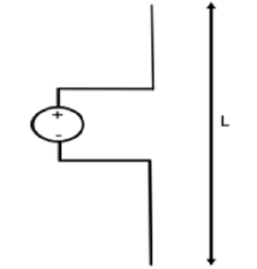
Figure. Dipole
The circuit diagram of a short dipole with length L is shown. The actual size of the antenna does not matter. The wire that leads to the antenna must be less than one-tenth of the wavelength. That is
L<λ/10
Where
Another type of short dipole is infinitesimal dipole, whose length is far less than its wave length. Its construction is similar to it, but uses a capacitor plate.
Q3) Explain the fields of short dipole?
If the short dipole antenna is oriented along the z-axis with the center of the dipole at z=0, then the current distribution on a thin, short dipole is given by:
I(z) = Io(1-2|z|)/L
The current distribution is plotted in Figure 2. Note that this is the amplitude of the current distribution; it is oscillating in time sinusoidally at frequency f.
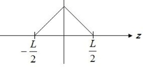
Figure . Current distribution.
The fields radiated from the short dipole antenna in the far field are given by:
E = jnkIoL e-jkr / 8πr sin
Hɸ = E /
/ 
Er = Hr= E ɸ = H =0
=0
Q4) Explain radiation resistance of short electric dipole?
The radiation resistance of any antenna can be expressed as:
Rrad=2Prad|Io|−2 --------------------------(1)
where |Io| is the magnitude of the current at the antenna terminals, Prad is the resulting total power radiated.
For an ESD
Prad = ղ |Io| 2 (βL)2 / 48 π
Rrad ≈ղ (β L)2 / 24 π
We know that
Β L = 2π/λ L = 2π. L/λ
where L/λL/λ is the antenna length in units of wavelength
Rrad≈20π2(L/λ)2
Q5) Write a short note on thin linear antenna?Explain radiation resistance of λ/2?
Thin antenna means its diameter is small compared to its wave length, i.e Where d= diameter of the antenna and λ= wavelength Antenna is fed at the center by a balanced two wire transmission line and assuming sinusoidal current distribution along various length of line as shown in figure

Figure . Thin linear antenna.
Radiation resistance of λ/2 antenna.
L = λ/2 the magnitude of current distribution is given by
I mag = Io sin[ 2π/λ[ λ/4 +z]
= Io sin[ π/2  2πz/4]------------91)
When z=0 I mag = Io [ ie maximum value of current at the centre]
When z =  λ/2 I mag = 0
When L= λ/2 the pattern factor becomes
E = [ cos [ π/2 cos / sin
/ sin  ]
]
The pattern is as shown in figure 3.9(a), it is slightly more directional than the pattern of infinitesimal of short dipole [which is given by sinθ]. The beam width between half power points of λ/2 antenna is 780 as compared to 900 for a short dipole
Q6) Explain broad side array and end fire array?
A broadside array consist number of identical antennas placed parallel to each other along a straight line. This straight line is perpendicular to the axis of individual antenna. It is known as axis of antenna array. Thus, each element is perpendicular to the axis of antenna array. All the individual antennas are spaced equally along the axis of the antenna array. The spacing between any two elements is denoted by‗d‘. All the elements are fed with currents with equal magnitude and same phase. As the maximum point sources with equal amplitude and phase radiation is directed in broadside direction i.e. perpendicular to the line of axis of array, the radiation pattern for the broadside array is bidirectional. Thus, we can define broadside array as the arrangement of 75 antennas in which maximum radiation is in the direction perpendicular to the axis of array and plane containing the elements of array. Now consider two isotropic point sources spaced equally with respect to the origin of the coordinate system as shown in the Figure. Assume that the two point sources are with equal amplitude and phase.
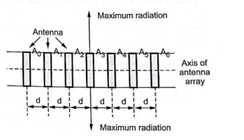
Figure . Broad side array
The end fire array is very much similar to the broadside array from the point of view of arrangement. But the main difference is in the direction of maximum radiation. In broadside array, the direction of the maximum radiation is perpendicular to the axis of array; while in the end fire array, the direction of the maximum radiation is along the axis of array.

Figure . End fire array
Thus, in the end fire array number of identical antennas are spaced equally along a line. All the antennas are fed individually with currents of equal magnitudes but their phases vary progressively along the line to get entire arrangement unidirectional finally. i.e. maximum radiation along the axis of array. Thus end fire array can be defined as an array with direction of maximum radiation coincides with the direction of the axis of array to get unidirectional radiation.
Q7) Explain the construction of Yagi antenna?
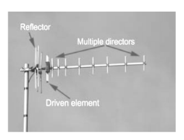
Figure . Yagi antenna components
There are three types of element within a Yagi antenna:
in reducing the levels of interference received.
Typically a reflector will add around 4 or 5 dB of gain in the forward direction.
Q8) Write a short note on long wire antenna?
A long wire antenna is an antenna that is a wavelength or more, but other definitions imply the antenna should be several wavelengths long.
Long wire antenna characteristics
If a wire antenna is half a wavelength long, then it will perform very much like a dipole, the main difference being that it is end fed.
The radiation pattern for a dipole is given in the diagram below.
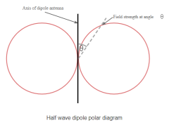
Figure . Long wire antenna
The same radiation pattern is exhibited for an equivalent end fed wire, however, as the length of the end fed wire is extended in terms of the number of wavelengths, it is found that the radiation pattern becomes more complicated.
A number of different lobes form and these move out towards the the line of the axis of the wire of the antenna, aligning further with this as the length is extended.
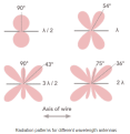
Figure . Patterns
It can be seen that the radiation pattern of this long wire antenna is very different to that of the half wave antenna. As the length of the antenna increases, so the major lobes align further with the axis of the antenna.
Q9) Write a short note on folded dipole antenna?
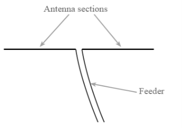
Figure 14. Basic dipole antenna
Q10) Explain its applications?
There are many ways in which folded dipoles can be used. They find uses in many applications:
Folded dipole antennas are sometimes used on their own, but they must be fed with a high impedance feeder, typically 300 ohms. This on its own can be very useful in certain applications where balanced feeders may be used.
However folded dipoles find more uses when a dipole is incorporated in another RF antenna design with other elements nearby. The issue is that incorporating a dipole into an antenna such as a Yagi where elements are closely coupled reduces the feed impedance. If a simple dipole was used, then the feed impedance levels of less than 20 Ω or less can easily be experienced.
Sometimes folded dipoles may be employed purely to give a greater bandwidth. When used to increase bandwidth, folded dipoles may be used on their own or within another antenna system.