Unit 5
Wave Propagation
Q1) Explain plane earth reflection?
In considering reflections introduced by the environment, the most significant source of reflections in terrestrial links is the earth’s surface itself.

Figure . Plane earth reflection
Sample E-field vectors are shown for the parallel and perpendicular polarization cases. There are two paths from the transmitter (TX) to the receiver (RX):
a line-of-sight (LOS) path and a reflected path. The polarizations of the components shown are also consistent with what we have sketched and derived earlier for the case of a TE/TM polarized wave incident upon a media interface.
The polarization of the LOS path, regardless of the TE/TM polarization case, remains constant; however, for the reflected path, the polarization of the reflected components are shown 180 degrees out of phase with the LOS path.
This results when θi → 90◦ (grazing incidence) at an interface with lossy dielectric (not a PEC). The grazing angle assumption is valid since in many cases the antenna heights h1, h2 are very small compared to the TX-RX separation. We also assume that the earth is treated as a flat surface for this development.
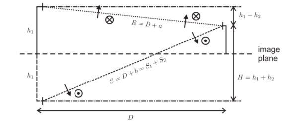
Figure .Flat surface
The two paths to the receiver in this case consist of the LOS path (of length R = D + a) and the reflected path (of length S = D + b). That is, each path is an additional length a or b longer than the horizontal separation distance D. Analyzing the larger of the two triangles in the diagram
H2 + D2 = S2 = (D+b) 2 = D2 + 2Db+ b2 ---------------(1)
Sincw D<<b H2 ≈ 2Db -> b = H2 /2D =(h1+h2)2/2D -------(2)
Similarly, the geometry of smaller triangle gives
a = (h1-h2) 2/ 2D --------------------------------------------------------------(3)
Using the principle of superposition, the electric field strength at the receiving antenna is proportional to
e -jβR/R – e -jβS/S = e -jβR/R [ 1- e -jβ(S-R) / S/R] -----------------------------------(4)
The term in parentheses is recognized as a correction term for the reflection, a kind of array factor for an antenna and its image, where the image produces a field of opposite sign as the line-of-sight path because of 180◦ phase shift introduced at the reflection interface. The term outside the parentheses is just a standard line-of-sight propagation term that we also see from an antenna.
Q2) Explain space wave propagation?
Space wave propagation is defined for the radio waves that occur within the 20km of the atmosphere ie; troposphere, comprising of a direct and reflected waves. These waves are also known as tropospheric propagation as they can travel directly from the earth’s surface to the troposphere surface of the earth. It is also known as a line of sight propagation as the signals are sent in a straight line from the transmitter to the receiver.
To prevent attenuation and loss of signal strength, the height of the antennas and distance between them can be given as:
Dm = (2RHt)-½ + (2RHr)-½
where,
Dm: distance between the two antennas
R: radius of the earth
Ht: height of transmission antenna
Hr: height of receiver antenna
Q3) What are the effects of imperfect earth?
Earth is basically imperfect and electrically rough. When a wave is reflected from perfect earth its phase change is 180 o. But actual earth makes the phase change different from 180 o. The amplitude of ground reflected ray is smaller than that of direct ray.
The field at the receiving point due to space is reduced by earth’s imperfection and roughness
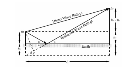
Figure . Imperfect earth
The received signal is the sum of two components. The line- of -sight distance is that exact distance at which both the sender and receiver antenna are in sight of each other. So, from the above line if we want to increase the transmission distance then this can be done by simply extending the heights of both the sender as well as the receiver antenna. This type of propagation is used basically in radar and television communication.
Q4) What are the effects of curvature of earth?
In a trunked repeater system multiple repeater are under the control of a computer system that can transfer a user from an assigned but busy repeater to another, available repeater, thus spreading the communication load. Communication satellites act as fixed repeater stations. The receiver-transmitter combination within the satellite is known as transponder.
The propagation of space and ground wave are limited by the curvature of earth.
So, for long distance communication of thousands of km or more are performed by sky waves or ionospheric waves.
Example: Armature radio
Q5) Explain the structural details of Ionosphere?
The distinct D, E, and F layers is a convenient way of picturing the structure of the ionosphere but not exactly correct. Ionisation exists over the whole of the ionosphere, its level varying with altitude. The peaks in level is considered as the different layers . Hence the terminology D, E, and F regions is more appropriate.
There is also a C region below the others, but the level of ionisation is so low that it does not have any effect radio signals and radio communications and rarely used.
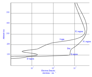
Figure 5. Ionosphere
When a sky wave leaves the Earth's surface and travels upwards, the first region of interest that it reaches in the ionosphere is called the D layer or D region.
The D layer or D region mainly has the affect of absorbing or attenuating radio communications signals particularly in the LF and MF portions of the radio spectrum, its affect reduces with increasing frequency.
This region attenuates the signals as they pass through. The level of attenuation depends on the frequency. Low frequencies are attenuated more than higher ones. In fact it is found that the attenuation varies as the inverse square of the frequency, i.e. doubling the frequency reduces the level of attenuation by a factor of four. This means that low frequency signals are often prevented from reaching the higher regions, except at night when the region disappears.
Attenuation = k/f2
Where:
k = constant
f = frequency of operation (Hz)
The E region or E layer is above the D region. It exists at altitudes between about 100 and 125 kilometres. Instead of attenuating radio communications signals this layer refracts them, often to a degree where they are returned to earth. As such they appear to have been reflected by this layer. However, this layer still acts as an attenuator to a certain degree.
At the altitude where the E layer or E region exists, the air density is very much less than it is for the D region. This means that when the free electrons are excited by radio signals and vibrate, far fewer collisions occur. As a result, the way in which the E layer or E region acts is somewhat different. The electrons are again set in motion by the radio signal and tend to re-radiate it. As the signal is travelling in an area where the density of electrons is increasing, the further it progresses into the region, the signal is refracted away from the area of higher electron density. In the case of HF signals, this refraction is often sufficient to bend them back to earth. In effect it appears that the region has "reflected" the signal.
The F1 layer is found at around an altitude of 300 kilometres with the F2 layer above it at around 400 kilometres. The combined F layer may then be centred around 250 to 300 kilometres. The altitude of the all the layers in the ionosphere layers varies considerably and the F layer varies the most. Being the highest of the ionospheric regions it is greatly affected by the state of the Sun as well as other factors including the time of day, the year and so forth.
The F layer acts as a "reflector" of signals in the HF portion of the radio spectrum enabling world -wide radio communications to be established. It is the main region associated with HF signal propagation.
Q6) Explain LOS propagation?
Among the modes of propagation, this line-of-sight propagation is the one, which we would have commonly noticed. In the line-of-sight communication, as the name implies, the wave travels a minimum distance of sight. Which means it travels to the distance up to which a naked eye can see. Then we need to employ an amplifier cum transmitter here to amplify the signal and transmit again.
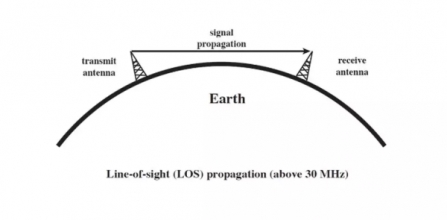
Figure . LOS
The line-of-sight propagation will not be smooth if there occurs any obstacle in its transmission path. As the signal can travel only to lesser distances in this mode, this transmission is used for infrared or microwave transmissions.
Q7) Explain reflection and refraction of sky waves?
When a radio wave is transmitted into an ionized layer, refraction, or bending of the wave, occurs.
Refraction is caused by an abrupt change in the velocity of the upper part of a radio wave as it strikes or enters a new medium.
The amount of refraction that occurs depends on three main factors:
Density of ionization of the layer,
Frequency of the radio wave, and
Angle at which the wave enters the layer
Reflection:
When high-frequency signals enter the ionosphere at a low angle they are bent back towards the earth by the ionized layer.
• When operating at frequencies just below the MUF, losses can be quite small, so the radio signal may effectively "bounce" or "skip" between the earth and ionosphere two or more times.
• If the ionization is not great enough, the wave only curves slightly downwards, and subsequently upwards as the ionization peak is passed so that it exits the top of the layer only slightly displaced. The wave then is lost in space.
• To prevent this a lower frequency must be chosen.
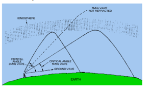
Figure . Reflection
Q8) Explain Ray path and critical frequency?
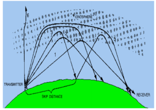
The various angles at which RF waves strikes the layer are represented by dark lines and designated as rays 1 through 6.
Ray 1 -- the propagation path is long.
Ray 2 and Ray 3-- the rays penetrate deeper into the layer but the range of these rays decreases.
When a certain angle is reached (Ray 3), the refraction of the ray is first returned to Earth , its second refraction from the ionospheric layer.
Ray 4 and Ray 5--the RF energy penetrates the central area of maximum ionization of the layer. These rays are refracted rather slowly and are eventually returned to Earth at great distances.
Ray 6-- the ray is not returned at all, but passes on through the layer.
The critical frequency is an important figure that gives an indication of the state of the ionosphere and the resulting HF propagation.
It is obtained by sending a signal pulse directly upwards.
Critical frequency is defined as the maximum frequency at which the total internal reflection(TIR) takes place from the ionosphere.
The mathematical representation is given as:
Fc = 9  Nmax
Nmax
Where, f c is the critical frequency in Hz
Nmax is the maximum electron density /ionization density (electrons per cubic meter)
Critical frequency varies depending upon atmospheric conditions, time of the day and the angle of incidence of the radio waves by the antenna.
Q9) Explain MUF and LUF?
Maximum usable frequency
• When a signal is transmitted using HF propagation, over a given path there is a maximum frequency that can be used.
• A maximum frequency that can be used for communications between two given locations. This frequency is known as the MUF.
• Waves at frequencies above the MUF are normally refracted so slowly that they return to Earth beyond the desired location or pass on through the ionosphere and are lost.
• However, that use of an established MUF certainly does not guarantee successful communications between a transmitting site and a receiving site. Variations in the ionosphere may occur at any time and consequently raise or lower the predetermined MUF.
The mathematical representation of critical frequency as a function of MUF is:
Fc = fMUF / sec  fMUF = fc/cos
Where, f c is the critical frequency in Hz
fMUF is the maximum usable frequency (3 to 4 times of f c )
θ is the angle of incidence The factor sec θ is called the MUF factor and it is a function of the path length if the height layer is known.
Lowest usable frequency
As there is a maximum operating frequency that can be used for communications between two points, there is also a minimum operating frequency. This is known as the LUF.
As the frequency of a radio wave is lowered, the rate of refraction increases. So the wave whose frequency is below the established LUF is refracted back to Earth at a shorter distance than desired, as shown in Figure.
The LUF is defined as the frequency at below which the signal falls below the minimum strength required for satisfactory reception.
The LUF is the practical limit below which communication cannot be maintained between two particular radio communications stations.
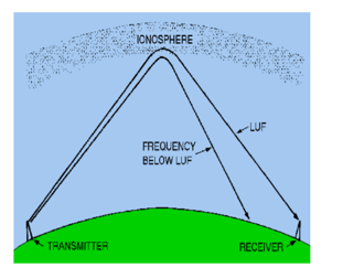
Refraction of frequency below LUF.
Q10) Explain virtual height and skip distance?
When a wave is refracted, it is bent down gradually, but not sharply. However, the path of incident wave and reflected wave are same if it is reflected from a surface located at a greater height of this layer. Such a greater height is termed as virtual height.

Figure Curve path
As shown in Figure, the curve path reaches an altitude of h1 before being returned to the Earth.
If the incident and returned rays are extrapolated to a vertex, they meet at a height h’, which is called the virtual reflection height of the ionospheric layer.
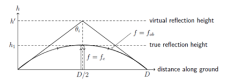
Figure 15. Curved path of refracted ray associated with frequency fob.
Skip distance sky zone
The skip distance is the distance over the Earth's surface between the point where a radio signal is transmitted, and the point where it is received having travelled to the ionosphere, and been refracted back by the ionosphere.
D skip = 2h  (fMUF/fc) 2 - 1
Where, Dskip: skip distance
h: height at which reflection happens
fMUF: maximum usable frequency
f c : critical frequency
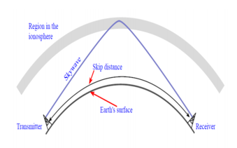
Figure . Sky zone
The size of the skip distance depends on
The SKIP ZONE is a zone of silence between the point where the ground wave becomes too weak for reception and the point where the sky wave is first returned to Earth.
The size of the skip zone depends on the extent of the ground wave coverage and the skip distance.
When the ground wave coverage is great enough or the skip distance is short enough that no zone of silence occurs, there is no skip zone.
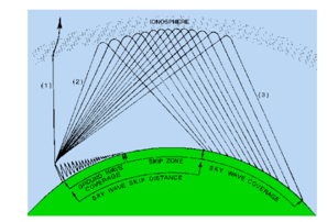
Figure Relation between skip zone , skip distance and ground coverage.