Unit-5
Information Theory
Q1) For a systematic (6,3) linear block code the parity matrix P is given by
P = 
R = [r1 r2 r3 r4 r5 r6]
A1)
Given n=6 and k=3 for (6,3) block code
Since k=3 there are 23 = 8 message vectors given by
(000),(001),(010),(011),(100),(101),(110),(111)
The code vector is found by
[C]= [D][G]
[G] = {Ik|P]= [I3|P]
1 0 0 | 1 0 1
0 1 0 |0 1 1
0 0 1|1 1 0
C = [d1 d2 d3] 1 0 0 | 1 0 1
0 1 0 |0 1 1
0 0 1|1 1 0
C= [d1,d2,d3,(d1+d3),(d2+d3),(d1+d2)]
Code name | Msg Vector | Code Vector For (6,3) liner block code |
| d 1 d 2 d3 | d 1 d 2 d 3 d 1+d 3 d2 + d3 d1 + d2 |
Ca | 0 0 0 | 0 0 0 0 0 0 |
Cb | 0 0 1 | 0 0 1 1 1 0 |
Cc | 0 1 0 | 0 1 0 0 1 1 |
Cd | 0 1 1 | 0 1 1 1 0 1 |
Ce | 1 0 0 | 1 0 0 1 0 1 |
Cf | 1 0 1 | 1 0 1 0 1 1 |
Cg | 1 1 0 | 1 1 0 1 1 0 |
Ch | 1 1 1 | 1 1 1 0 0 0 |
The code vector is given by
c 1 = d1, c2 = d2 , c3 = d3 c4 = d1 + d3 c5 = d2 + d3 c6 = d1 + d2
Since k=3 we require 3bit shift registers to move the message bits into it.
We have (n-k) = 6-3 = 3.
Hence we require 3-modulo 2 adders and 6 segment commutator.
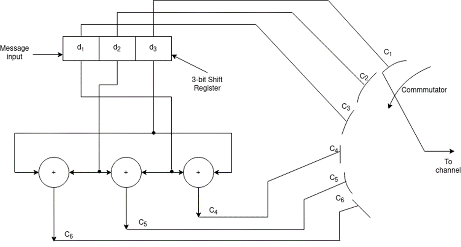
Fig.: 3-modulo 2 adders and 6 segment commutator
Q2) For the (6,3) code matrix HT is given by
H T =
1 | 0 | 1 |
0 | 1 | 1 |
1 | 1 | 0 |
1 | 0 | 0 |
0 | 1 | 0 |
0 | 0 | 1 |
Find P.
A2)
H T = [P/In-k] = [P/I3]
S= [s1 s2 s3] = [ r1 r2 r3 r4 r5 r6]
1 | 0 | 1 |
0 | 1 | 1 |
1 | 1 | 0 |
1 | 0 | 0 |
0 | 1 | 0 |
0 | 0 | 1 |
[S] = [S1 s2 s3] = (r1+r3+r4) , (r2+r3+r5),(r1+r2+r6)
S1 = r1+r3+r4
S2 = r2+r3+r5
S3 = r1 +r2 +r6
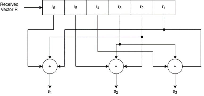
Fig.: Syndrome calculation circuit
Q3) For a systematic (6,3 ) linear block code the parity marix P is given by
P = 1 0 1
0 1 1
1 1 0
For the recorded code-vector R= [1 1 0 0 1 0] Detect and correct the single error that has occurred due to noise.
A3) Given
P = 1 0 1
0 1 1
1 1 0
P T = 1 0 1
0 1 1
1 1 0
Parity check matrix [H] = [P T | I n-k] = [ PT | I3 ]
1 0 1 1 0 0
0 1 1 0 1 0
1 1 0 0 0 1
H T = 1 0 1
0 1 1
1 1 0
1 0 0
0 1 0
0 0 1
S = [s1 s2 s3] = R HT= [ 11 00 10] 1 0 1
0 1 1
1 1 0
1 0 0
0 1 0
0 0 1
[S]= [100] since s≠0 it represents error. Since [100] present in the 4th row of HT . So the error vector [E] = [0 0 0 1 0 0 ] the the corrected vector is given by
C = R + E = [11 00 10][000100]
C = [110110] which is the valid code
Q4) Design an encoder for the (7,4) binary cyclic code generated by
g(x) = g0 + g1 + g2 x2 + …………………..+ gn-k x n-k
A4) Here for (7,4) cyclic code given
g(x) = 1 + x + x3
Comparing (1) and (2) we get
g 0 =1, g1 =1 , g2 = 0, g3 = 1
With these values the design requires 3 flipflops R0,R1,R2 , the two modulo-2 adders and connection from the output of the gate to R0 and to the first modulo-2 adder.
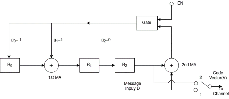
Fig.: Modulo-2 adder
Q5) For a (7,4) cyclic code the received vector Z(x) = 1110101 and the generator polynomial g(x) = 1+x+x3. Draw the syndrome calculation circuit and correct the single error in the received vector.
A5) The generator polynomial is given by
1+x+x3 ----------------(1)
Now comparing eq(1) with
g(x) = g0+g1+g2 x2 + g3 x3
The co-efficient g0=1,g1=1,g2=0,g3=1.
With these values the circuit requires only 3 flip flops (s0,s1,s2) representing the syndrome bits two modulo-2 adders.
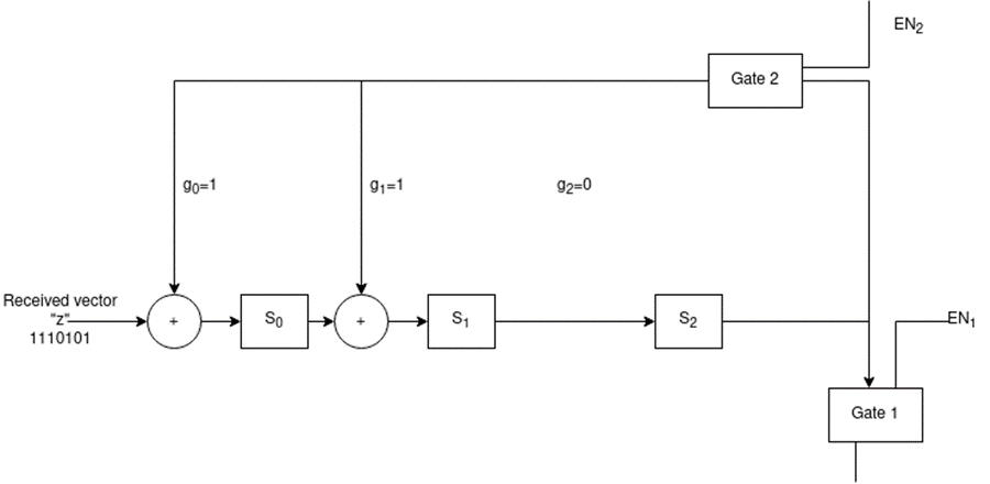
Fig.: Syndrome decoder with 3 flip flops
Q6) Explain how syndrome calculator for (7,4) cyclic code.
A6)
Number of shifts | Input Z(x) | Shift register contents | Comments |
Initialization gate1-oFF and gate-2 ON |
| 000 | Shift register contents are cleared |
1 | 1 | 100 |
|
2 | 0 | 010 |
|
3 | 1 | 101 |
|
4 | 0 | 100 |
|
5 | 1 | 110 |
|
6 | 1 | 111 |
|
7 | 1 | 001 | Indicates error |
8 | 0 | 110 |
|
9 | 0 | 011 |
|
10 | 0 | 111 |
|
11 | 0 | 101 |
|
12 | 0 | 100 | Endof shifting operation |
The received vector is 1110101
Since we got 100 at the 12th shift the th bit counting from right is in error.
Error vector E =0010000
Corrected vector V = Z + E = 1110101 + 0010000
V = 1100101
Q7) Suppose the number of outputs of the function generator polynomial that generate each 3-bit output sequence as 1,2 and 3. Similarly, the number each corresponding function generator.
A7) Since at the first stage (m1) is connected to the first generator function polynomial the generator is
g 1 = [1 0 0 ]
g1(x) = 1.
The second generator is connected to stage 1 (m1) and stage 3(m3)
g 2 = [ 1 0 1 ]
g2 = 1 + x 2
g3 = [1 1 1]
Generator for this code = [ 100, 101, 111]
The output of modulo-2 adders are C1, C2 and C3
C1 = m(x) g1(x)
C2 = m(x) g2(x)
C3 = m(x) g3(x)
The codeword for convolutional encoder is
C = [ c1 c2 c3]
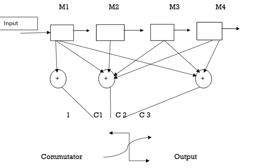
Fig.: Convolutional encoder
Here n = 3, m = 4 , Length of data = 5
C = n(L+m) = 3(5+4) = 27 bits
Constraint length k = m + 1 = 5
The coded output c1,c2 ,c3 are
c1 = s1
c2 = s1  s2
s2  s3
s3  s4
s4
c3 = s1  s3
s3 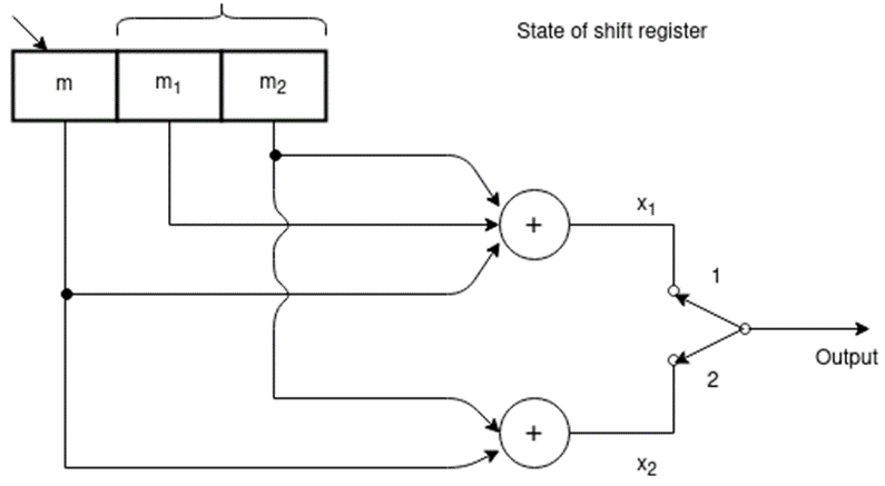 s4
s4
We assume that initially the shift register is clear. During the first shift
M1 = 1 M2 = M3=M4 = 0
C1 = s1 = 1
C2 = = s1  s2
s2  s3
s3  s4 = 1
 0
0 0
0 0 =1
0 =1
C3 = s1  s3
s3 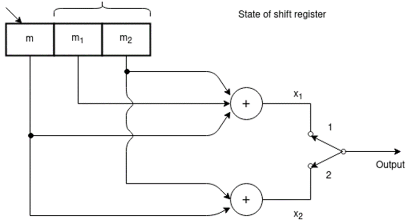 s4= 1
s4= 1  0
0 0 = 1
0 = 1
The coded output for tbis message bit is 111
C = 111 010 100 110 001 000 011 000 000
Q8) Assume a (2,1) convolutional encoder with constraint length 6. Draw the tree diagram, state diagram. Design the block code for a message block of size eight that can correct single errors.
A8) Here:
n = 2 and k =1 and K = 6 (constraint length)
M = K/n = 6/2 = 3 since constraint length k = n * M
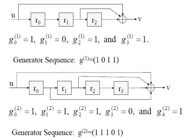
Generator Sequence:
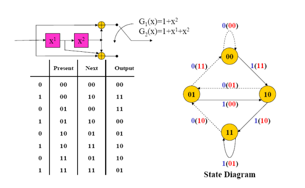
This is derived from the formula:
g (i) D = g (i) 0 + g1(i) D + g2 (i) D2 +………..+ gm (i) DM
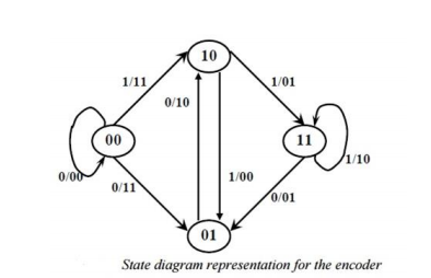
Q9) Define: a) state diagram representation. b) tree diagram representation. c) trellis diagram representation.
A9)
a) State Diagram Representation: A convolutional encoder may be defined as a finite state machine. Contents of the rightmost (K-1) shift register stages define the states of the encoder. So, the encoder in has four states. The transition of an encoder from one state to another, as caused by input bits, is depicted in the state diagram. A new input bit causes a transition from one state to another
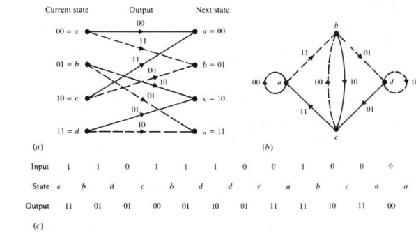
Fig.: State diagram
b) Tree Diagram Representation: The tree diagram representation shows all possible information and encoded sequences for the convolutional encoder. The encoded bits are labeled on the branches of the tree. Given an input sequence, the encoded sequence can be directly read from the tree
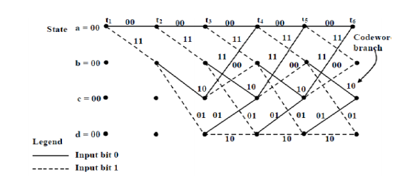
Fig.: Tree diagram
c) Trellis Diagram Representation
The trellis diagram is obtained from the state diagram. All state transitions at each time step are explicitly shown in the diagram. The supporting descriptions on state transitions corresponds to input and output bits . Trellis diagram describes the operation of the encoder.
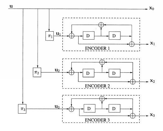
Fig.: Trellis diagram
Q10) Explain Encoding and decoding using Reed Solomon Code
A10) The method of encoding in Reed Solomon code has the following steps −
At the receiving end, the following decoding procedure done −
Q11) Explain turbo codes in detail.
A11) A turbo code in essence consists of the parallel concatenation of two or more convolutional constituent codes separated by an interleaver. A particular example of a turbo code, hereafter called PCCC (Parallel Concatenation of Convolutional Codes).
The encoder contains three parallel recursive binary convolutional encoders with ml, m2, and m3 memory cells, respectively. D means delay, and TI, 7r2 and 7r3 mean interleavers (or permuters).
The interleaver is a pseudorandom block scrambler: A whole block of N bits enters the interleaver and read out in some specific(fixed) random order without repetitions. The input bits to each component encoder are designated as ul, u2 and uj. Generally speaking, 7r1, 7r2 and 7r3 may not be the same. The three component encoders may also be different and even have different coding rates.
In this example, these three components are identical. 71.1 is set to identity I, that is, no permutation at all. Thus, the first component encoder operates directly on the information bit sequence ul = u = (ul, . . . , uN) of length N, producing the two output sequences xo and xl. The second component encoder operates on a reordered sequence of information bits, u2, produced by a permuter 7r2, and outputs two sequences x; (not plotted in Figure 3.1) and x2 .
Here, only one sequence, x2, is transmitted. Similarly, the third component encoder operates on us, a reordered sequence of information bits permuted by 7r3. More specifically, the example code in Figure is a code rate r = a = a code which is generated by three component codes with memory ml = m2 = ms = m = 2 (i.e., constraint length K = 3), producing the outputs xo = u, xi = ui g, for i = 1,2,3, where the generator polynomials go(D) = 1 + D + D2 and gl (D) = 1 + D2, respectively. We use the encoder in Figure to generate an (n(N + m), N) block code. N is the block length, m is the tail bits' length.
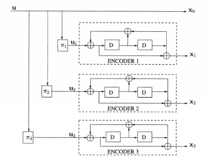
Fig.: Turbo codes