Unit - 3
Braking system, chassis and suspension system
Q1) Explain the general requirements of a braking system?
A1)
The safe and dependable use of automobile vehicles demands recurrent alteration of its speed in retort to changing traffic situations. This constraint is met by the braking system (BS).
The following are the requirements and functions that should be satisfied by the Braking System:
1. It should deaccelerate the automobile in a precise and controlled fashion.
2. It should cause the vehicle to halt as and when required
3. It must help the automobile to sustain a constant speed when moving downhill.
4. It must keep the automobile in still position on flat or gradient surface.
5. The braking must not involve any noise.
6. It should cause the automobile to drift away from its intended path.
7. Quick heat dissipation must be possible
Q2) Explain the working mechanism of a simple braking system with a neat sketch?
A2)
The working of simple braking system can be explained with the help of below figure.
For locking and controlling the speed of the wheel a brake shoe is pressed against the rim. A lever mechanism is used to increase the force of contact b/w the shoe and the rim and it is placed amid the handle and the shoe. Braking effectiveness is also increased with the help of mentioned principle. When an element i.e., sand, etc. is placed amid shoe and the rim the braking action become drastic due to increase coefficient of friction. At high speed due to less coefficient. Of friction the brake shoe holding capacity decrease. Both shoe and rim get heated as brakes are applied.
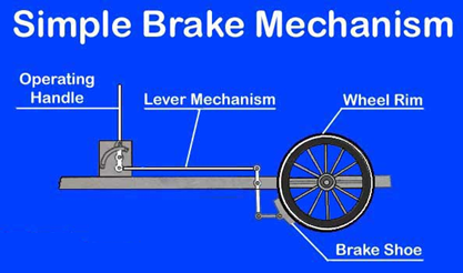
Fig Working of a Simple Braking System
Q3) Explain the phenomenon of weight transfer during braking on all four wheels.
A3)
Weight transfer is the change in load borne by different tyres (wheels) of rigid automobile during speeding up (acceleration), and the variation in centre of mass position relation to the tyres due to suspension amenability or changing load condition. Weight transfer depends on 3 states: acceleration, braking and turning left/right. In all the three conditions, the mechanical downforce (weight) on the wheel is continually changes.
The phenomenon can be best explained with the help of an example.
The vehicles (cars) in animated cartoon films display this concept. While accelerating, the forward-facing (front) wheels of the cartoon car kick from the earth leaning the car backward showing weight transferring from the front wheels on to the rear wheels. As brakes are applied or vehicle stops, the back tyres lift off and the car moves frontward. In this condition the weight gets transferred from the rear end to the front. When the car is steered, the inside wheels move to the air as the wt. Is transferred to the wheels on the outside.
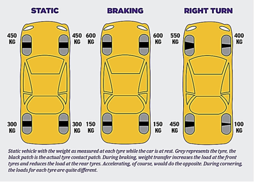
Fig Weight Transfer Concept
Let’s visualize a vehicle weighing 1,500kg, with a load distribution of 60 % and 40% at front and back respectively assuming weight distribution at sides being equal. In static position, the front and rear tyres have a load of 450kg and 300kg each, respectively. So, during speeding, weight moves to the rear from front wheels. During stopping, the weight is shifted to front from the rear. While steering, the weight is shifted to outside wheels from the inside. As such, if you are moving in right direction, the front right wheel becomes less in weight and load transfers to the back left tyre.
Q4) What is Braking Ratio and brake pedal ratio? What are the general ratios for front and rear wheel drives?
A4)
BR is the evaluation of front tyre braking effort in terms of back tyre braking effort. It is generally calculated as a percentage and defined as the mechanical force depressing the brake shoes against the tyres/wheels compared to the total car weight.
General Ratios for Braking
Rear Wheel Drive Automobiles
• Front side brake can control braking of 60 % to 70 %
• Back brakes can control braking of 30% to 40%
Front Wheel Drives Automobiles
• Mostly load is concerted at forward tyres
• BR is much more at front tyres
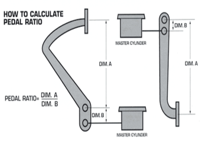
Brake Pedal ratio
It is generally the lever ratio or the measurement of mechanical advantage generated by the pedal.
Q5) How are brakes classified? Explain the working of drum brakes with a neat sketch.
A5)
The common classification of the brake is:
1.Based on power
- Mechanical
- Hydraulic
- Air and Vacuum
- Magnetic
2.Based on application
i. Service type
Ii. Parking type
3. Based on operation
i. Manually operated
Ii. Servo based
Iii. Powered operated
4. Application of Braking force
i. Single Acting
Ii. Double Acting
Working of Drum Brake
The most commonly used mechanical brake is the drum brake as shown in Figure.
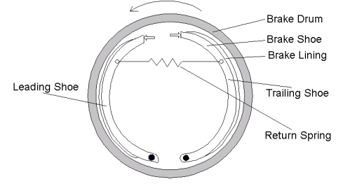
Fig Drum Brake
Drum brakes uses friction caused by a pair of brake shoe pressed outwardly against a brake drum that is rotating. The stopping is caused inside of a rotating drum, giving it a name. These are only available with low-cost bikes and scooter. However earlier cars and trucks also used these brakes.
As the brake is pressed, the lever (cam) causes the brake shoe to move forward and subsequently it is pressed against the break drum making the surface contact. Accordingly, the linings mounted on the shoe makes contact with the spinning drum and friction is generated resulting in production of heat. This friction ultimately causes to deaccelerate and stop the vehicle movement. When the force on the brake is released the return spring causes the shoe to return to its previous position causing the detachment between lining-shoe and drum. The vehicle can now move freely.
Q6) Explain hydraulic braking system with diagram. Also explain in brief master cylinder.
A6)
Hydraulic Braking System
These types of system make use of hydraulic/fluid pressure for pushing the brake shoes. Its works on PASCAL’S LAW principle which says that when a pressure is applied in any region/part of a closed incompressible fluid, it gets transmitted equally in all directions. This system consists a mechanism which uses brake fluid that may be glycol ethers, denatured alcohol, additives, etc. for transferring pressure from the controlling arrangement to the braking arrangement. As such this system works with the help of fluid, cylinder and friction. By generating the pressure inside the cylinder, the brake fluid causes the brake pads to stop the wheels.
In this system, as the brake pedal is pushed, a rod offers force on the piston(s) present in the cylinder known as master cylinder, causing the portion of brake fluid to stream into wheel cylinder (pressure chamber) via a relief port. The working of this system can be more clearly explained with the help of a line diagram as shown in Figure.
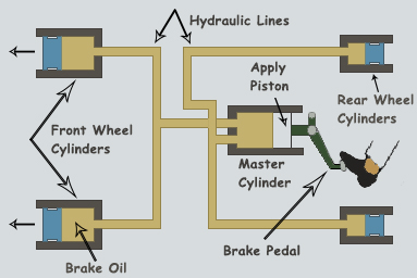
Fig Line diagram of Hydraulic Brakes
The system consists a master cylinder which is connected to different wheel cylinders at both front and rear wheels with the help of tubing. This whole system is filled with fluid when brakes are not operated. The brake shoes are mounted on inner of brake drum and linings on the outer portion of brake shoe. The pedal is connected with the help of piston to the cylinder. As the pedal is pressed forcing the piston into this cylinder, the hydraulic pressure is transmitted equally in 4 directions. The brake fluid through the tubing’s via inlet port enters to different cylinders, which in turn moves the wheel cylinder piston outwards. The piston thus forces the shoe against the wheel drum, making the vehicle stop. When the pedal pressure is released, master cylinder piston moves back to its previous position owing to the retracting spring pressure.
Master Cylinder
The Master Cylinder is the core member of this system. It contains 2 main chambers, one is the fluid tank encompassing the brake fluid, and second is the compressing compartment for piston movement. The fluid tank delivers the fluid to the brake system with the help of intake and relief ports. The master cylinder which is connected to different wheel cylinders at both front and rear wheels with the help of tubing
Q7) Explain the construction and working of a pneumatic braking system with diagram.
A7)
This method imparts high-power of braking. Air brakes uses compressed air instead of hydraulic fluid. These brakes can be any i.e., drum brakes, disc brakes, or a mixture of both. This is a kind of frictional brake for automobiles in which compressed air pressure on a pushrod (piston) is employed to supply the pressure to the brake shoe for deaccelerating the vehicle.
Components of pneumatic braking system
The important components of this system are shown in Figure below. It consists of a compressor used for maintain and building air pressure, a tank for holding the compressed air, a dryer for removing the excess air moisture, a safety valve for preventing the tank from bursting due to over-pressure and a foot valve/triple valve for drawing the air for brakes operation.
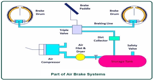
Fig Components of Brake System
Working of Pneumatic System
The working of this system is shown below in Figure. When the vehicle driver presses the pedal to stop the vehicle, the resulting events take place. As the engine is started, the compressor gets started which starts compressing atmospheric air. This compressed air is sent to the tank through the compressor governor.
Apart from above sequenced events as the driver presses the pedals, the outlet port of the triple valves gets closed and the inlet valve opens, resulting in passing of the compressed air from the tank to the brake lines of the system. The compressed air is then transferred to the brake cylinder from these lines pressuring this chamber. This chamber contains a piston which moves away from its normal position due to air pressure converting this air-filled energy into mechanical power. Due to the piston movement because of applied compressed air pressure, the mechanical actuator (Springs, slacks, etc.) inside the brake drum expands, pushing the brake pads in an outward direction creating a contact with the spinning drum lines and stopping the vehicle. As the pedal pressure is released the outlet port opens while the intake gets closed and the used air sail into the atmosphere.
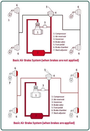
Fig Working of Air Brake System
Q8) What is ABS & its significance?
A8)
The full form of ABS is Anti-lock Braking System. ABS or often referred as anti-skid braking systems is a safety system used on different airplanes and other moving vehicles like cars, trucks, buses etc. ABS first came into existence in 1920s developed by a French researcher to assist braking on aircraft. In 1970's the modified and reformed version of ABS was presented to the commercial market. Today it is used in every car and motorcycle for steering and traction control.
The four major components of a typical anti-lock braking system are:
- Sensors - monitors how fast the wheels are spinning
- Valves - permits, blocks and relieve pressure on the brakes
- Pump - filled with fluid for applying pressure to the brake drums when needed.
Iv. Controller - Consist of an ECU (electronic control unit) which is the heart. It takes data from sensors and decide if pumping of the brake is required or not.
ABS works by releasing and then 'pumping' the brakes to automobile wheels in hard braking conditions. As the sensors notice that the speed of any wheel (s) is dipping significantly in comparison to other wheels, the ECU instantly sends the indication to the valves of the desired wheel(s) to reduce the pumping (brake) pressure, and the valves get shut off. After sometime, the wheels start to quicken again, sensor sends the signal to ECU, which in turn sends an indication to increase the brake pressure and open the valve and ultimately brakes are applied. This cycle keeps on repeating till brake application becomes normal. So fundamentally, this system works in three stages:
- Brake pedal is pressed/released
- Speed sensors detect skidding/ locking or decrease in speed
- Pumping the brakes
Significance of ABS
ABS prevents the automobile tyres/wheels from locking up and helps in maintain the steering control during braking by keeping tractive contact with the road surface.
When instant brakes are applied, there is a chance of an immediate loss of traction between the road and wheels leading to skidding of the tyres. The situation worsens if all this occurs irrepressibly. In this situation the automobile remains in motion, and the loss of traction may result in driver loosing steering control leading to a mishap. So here an ABS system provides rescue. As ABS functions, the brakes are pressed and relieved several times in a second. Due to this the tyres do not lock up during braking. The automobile slows in speed down retaining its grip, and the existing traction permits the driver to maintain navigation control. As such, the driver steers the automobile avoiding an accident.
ABS usually provides improved automobile control and minimizes stopping distances on desiccated, slippery, or snow-covered surfaces. ABS can also considerably maximize braking distance, while still providing steering control.
Q9) What is EBL & how it’s different from ABL?
A9)
It is also known as Electronic Brake Force Distribution (EBFD). It is an automated automobile braking technique (technology) used for automatically distributing the force applied on each automobile's wheels. The force distribution to each wheel depends on the road conditions, speed of the automobile, loading of the vehicle, etc.
The EBD consists of 3 major components:
i. Sensors: It determines the wheel along with the rate at which the vehicle is moving. These sensor senses that steering losing control and sends signals to ECU.
Ii. ECU: It’s used to measure the slip ratio (the difference b/w rate of tyre movement and vehicle speed) and send command to modulator for maintain the slip ration in reasonable range.
Iii. Force Modulators: These modulators control the braking force applied on each wheel.
Difference with ABS
EBL is a modification of the ABS and it make sure that the appropriate quantity of force is distributed to each tyres for bringing the vehicle to a completely stop. As ABS manages that the vehicle does not get locked up on heavy braking, EBD ensures that each wheel gets the suitable amount of braking force. Through EBD we can exert more or less braking force to each tyres for maximizing the stopping power though maintaining steering control.
When brakes are applied and the vehicle slows down, its weight shifts to front end. This increased weight at front maximizes the grasp of the front tires but it reduces the grip at rear end making the rear tires to slip. As such car can tail in one direction or even spin. With ABS the different wheel valves do not provides an adequate solution. To solve this problem modern vehicles are provided with EBL/EBD. With EBD, ECU regulates the slip ratio of each of the wheels independently. As the rear wheels are in danger of slipping, ECU applies less force to rear end while sustaining the force exerted to the front wheels.
EBD is also beneficial when the vehicle is braking while making a turn. During turning, rotation of the outer tyres is more swift as compared to inner tyres. If heavy braking is applied to inside tyres, they can get lock causing oversteering and slipping of the vehicle. EBD senses the slippage of the inside tyres and reduces the brake pressure on these tyres without compensating the force on the outside tyres.
Q10) Write Short Notes on (i) Thermal Aspects in Braking (ii) Traction Control System.
A10)
Thermal Aspects
When two bodies rub or slide against one another the heat is generated due to friction known as frictional heat. This frictional heat is only generated of proper magnitude if both the bodies rub/move/slide amongst each other with a relative speed and some pressure of contact. In case of braking this heat of friction is produced at rolling (sliding) interface of wheel (brake drum) and brake shoe contact, and wheel/rail contact. This frictional heat is generated at these interfaces as the kinetic energy degenerate between the two contacting bodies significantly raising the temperature at the part of contact.
During the operation of braking, the heat (thermal) energy created from the kinetic energy is generally classified into two parts:
i. The major portion of the heat is first absorbed by the brake disc and brake pad by mechanism conduction and then progressively emitted into the surroundings after the braking
Ii. The other left heat part is distributed directly into the surroundings from the friction surfaces by process of radiation and convection and radiation.
Traction Control System (TCS)
TCS objective is to regulate and uphold the vehicle stability during acceleration manoeuvres, i.e., avoiding spinning of the wheels when speed up on steep grade or a low frictional surface. TCS is a dynamic automobile safety technique. It prevents loss of traction of the wheels driven on roads.
TCS becomes operational when the wheel torque and throttle input mismatches with the driving surface. TCS becomes handy in extreme weathers involving rainfall, snow and on slippery surfaces offering minimal to no grip. It allows the vehicle them to build up speed without losing grip.
The above-mentioned advantages are attained by the optimization of separate wheel torques by controlling the combination of different fuels, ignition system and brake torque of driven wheel.
Q11) What are vacuum brakes? What is the major advantage and limitation of these brakes over air brakes?
A11)
This is a substitute to the pneumatic brake. These brakes were introduced around the 1865s, nearly the same period as the pneumatic brakes. This form of brake works by the action of atmospheric pressure acting on a piston placed inside a vacuum chamber. The vacuum brake has been used since long in locomotives, trains etc. in UK and different countries whose railway system is dependent on UK instead of pneumatic brakes as the regular, fool proof, dependable and reliable train brake.
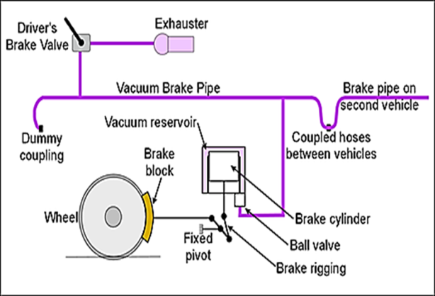
Similar to pneumatic brake, these brake systems are also monitored through a brake pipe. These pipes are connected to a brake valve in the driver's cab. These valves are connected with braking equipment on each automobile. The intensity and condition of the vacuum pressure created by ejector (exhauster) governs the operation and working of the brake equipment connected with every automobile. The ejector/exhauster, using steam on steam engine, or using electrical power on other kinds of locomotives, creates vacuum by eliminating atmospheric pressure from the pipe brake. Under full vacuum condition, the brakes are released. At normal atmospheric pressure, the brakes are fully applied. The various important parts of this system as applicable to electric/diesel train are shown in the above figure.
Advantage and limitation over Air Brakes
One major advantage of vacuum brake over the original pneumatic brake system is that it can offer a partial release which pneumatic brake might not and works at very high pressure.
Though, it is slow in process than the pneumatic brake. For speeding up the train an accelerator valve is used.
Q12) What is the function of chassis? What types of loads are sustained by the chassis?
A12)
The chassis (Frame) acts as a framework on which automobile engine, tyres, brakes, suspensions etc. ride. During vehicle movement and braking, the chassis sustains the reaction forces of the tyres and also engrosses wind forces and road shocks through the absorbers/suspension. As such, the chassis design must be such that it can make best use of payload capability and provide reliability, adaptability, flexibility and acceptable performance.
The different loads/weight sustained by the chassis frame are
1. Less duration Load - This occurs while passing a broken patch.
2. Temporary duration Load – occurs while taking a curve.
3. Impact Loads - Due to vehicle collision.
4. Static Loads - Loads occurring due to different parts of chassis.
5. Inertia Load - During brakes application
6. Very Heavy Loads (Overload) – Beyond the capacity of design.
7. Vertical Loads: Occurs while bumping
8. Load due to torque: Two loads i.e., Engine torque and braking torque which bend the side members in the vertical plane is sustained by the chassis.
Q13) What necessary condition must be fulfilled by an automobile body?
A13)
We know that there are diverse types of loads acting on a body. There are different loads for different types of bodies.
The body of the most vehicle should fulfil the following requirements:
- It should be light and consists of minimum number of components or part.
- Must provide sufficient space for luggage and passengers.
- It must endure shocks and vibrations while moving.
- Must offer minimum resistance to air.
- Cheap and easy in manufacturing.
- Attractive shape and colour.
- Uniformly distribution of load must be there.
- Less failure life.
Q14) What is the difference b/w chassis strength and stiffness? Discuss the role of these important parameters in chassis design?
A14)
Chassis Strength can be defined as the ability of a frame to sustain the load before it breaks.
Stiffness is a measure of how much the chassis will twist under the loads transferred to it from the suspension
Role of Strength and Stiffness
Chassis strength and stiffness are two major aspects that needs consideration while designing a vehicle. Chassis/ Frames are the main structure for road vehicle design. In overall viewpoint a chassis can be considered as a specific combination of material to resist loads. As such the strength of the chassis must be critically considered while design and analysis. It directly affects the stability and safety of vehicle. Because most of load are fully distribute along the chassis.
According to researcher Herb Adams, the frame apart from being strong must also be stiff. The chassis stiffness is a result of its geometry. The major loads sustained by the chassis includes mounting loads, aero dynamics, braking load, road abnormalities, and inertia loads during vibrations. Also, the frame must with stand impact loads that includes the bending and torsion loads, joint bending and torsion, also lateral and longitudinal loads. As such chassis must be strong in stiffness while designing rather than strength.
For performance of automobile, this stiffness number is very important. The highly stiffened chassis gives low deformation under load, and vice versa. If low stiffness and high deformation of chassis is there, the automobile will not be operational as desired due to chassis design deformation leading to improper working of machineries mounted to the deformed chassis. As such, the chassis must be stiffened in ample amount to cause less deformation under loading but cannot be completely stiff as it will lead to brittleness.
The chassis must be always be designed to have enough stiffness for resisting torsion and bending. Often the torsional stiffness or torsional rigidity of a car chassis is measured. It is usually measured in units of Nm/deg or lb-ft/deg. Torsional stiffness determines the resistance that chassis has when a change in degree occurs while twisting. Bending stiffness is defined as the resistance of the chassis against bending deformation for applied transverse loading. Unit of bending stiffness is kN/mm.
Q15) What do you understand by Independent Suspension?
A15)
Independent Suspension
The independent suspension system means an arrangement connecting the wheels to the frame in which raise or fall of one wheel has no direct effect on the other wheel. Independent suspension allows each wheel on the same axle to move vertically (i.e., reacting to a bump on the road) independently of the others. The position of each wheel is independent of the other one.
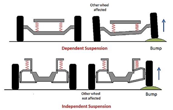
Fig Suspension System
Mostly today’s automobiles have independent front suspension (IFS). Some vehicles also have an independent rear suspension (IRS). A fully independent suspension has an independent suspension on all wheels.
Some early independent systems used swing axles, but modern systems use MacPherson struts, trailing arms, leaf springs etc.
Q16) What do you understand by Front Independent Suspension? Explain its advantages over beam/axle suspension?
A16)
Independent Front and Rear Suspension
There are different types of independent front suspension available in market:
- Coil Spring
- Leaf Spring
- Torsion Bar
- Mc Pherson Strut
- Double Wishbone
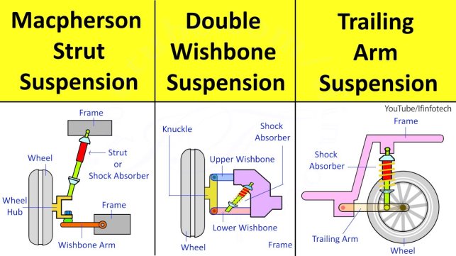
Fig Different types of Independent System
The simplest is the coil spring type suspension system. This suspension uses a coil spring which offers springing action to the suspension. The spring sits between the two arms. One arm is attached to the frame.
The other type i.e., McPherson Strut uses a special unit consisting of a spring and shock-absorber. It was named after its inventor McPherson. Lower wishbone is only used as was the case with the double wishbone design. It consists of a strut containing shock absorber and the coil spring mounted on the wheel. The wishbone is used for wheel positioning as well as takes the accelerating, braking and side forces. This system is simpler in construction and commonly used in the front wheel drive cars. This system with an antiroll bar offers improved road safety and ride ease, light and self-stabilizing steering.
Advantages over Beam Suspension
Due to a numerous limitation of the beam or swing axle suspension system, such as poor shock absorbing capacity, less loading capacity and springiness, the manufacturers use an improvised version i.e., IRS although former generation suspensions were simple in design, cheaper to manufacture and maintain. Ideally, a good front suspension system should possess springiness and damping qualities.
Most cars use independent front suspension. It provides softer springing action, good steering geometry and better road holding of wheels. Moreover, it improves the ride handling qualities of the vehicle.
Q17) What are perpendicular arm type suspension? How they are classified?
A17)
Perpendicular arm type
Perpendicular arm type suspension employs two trailing arms pivoted to the car body at the arm's front edge. The arm is comparatively large in comparison to other suspensions' control arms because it is in single piece. The upper surface supports the coil spring. It is securely fixed to the tyres at another end. This system only allows the wheel to move up and down to deal with bump. No lateral movement and camber change is allowed. As the car rolls while taking a turn, the arm rolls for the same degree as the car body, thus changing camber angle.
Classification
These systems can be trailing or semi trailing type.
The trailing link system use number of linkages lying beside the frame side members. A horizontal coil springs is used in this suspension system. Throughout compression and rebound, the spring winds and unwind itself. In some automobiles instead of coil spring a torsion bar is also be fitted.
Semi-trailing arms is a type of independent rear suspension. In comparison to non-independent suspensions, it provides better ride quality and handling, as a bump/hole under any one wheel did not change the configuration of the other wheels, and the unsprung weight lowers.
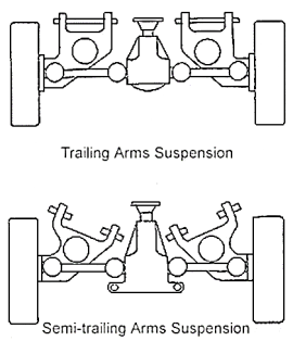
Fig Perpendicular Arm Suspension
Advantages of semi trailing over trailing suspension
Compared with the trailing arms suspension it has an advantage that during the suspension movement the camber angle changes, so that the tyres remain perpendicular to the ground during body roll.
Compared with other rear independent suspension systems, such as multi-link suspension, its merits are lower cost and simple in design and more compact.
Q18) What are Parallel Type Suspension? List the important function of Wishbone suspension.
A18)
Parallel Suspension
In automobiles, a parallel suspension system is an independent suspension design using wishbone-shaped arms for locating the wheel. Each wishbone (arm) has two mounting points i.e., one joint to the chassis and other at the knuckle. The shock absorber and coil spring mount to the wishbones to control vertical movement. Double wishbone type (Fig Diff types of independent suspension) is the most general type of Independent front suspension system (IFS). The use of coil springs (placed b/w the lower wishbone and cross member) with absorber in front axle is common in IFS.
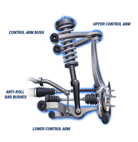
Fig 21 Parallel Suspension System
The upper and lower wishbone arms are pivoted to the frame member. The automobile weight is transferred from the main body and cross member to the coil spring through which it reaches lower wishbone. The shock absorber placed inside the coil spring is attached to the cross member and to lower wishbone member.
Functions of Wishbone Suspension
1.The wishbones position the wheels, transfers the automobile load to the springs, and resist acceleration, braking and side forces.
2. The upper wishbone arm is kept shorter in length than the to keep the wheel track constant avoiding the extreme wheel wear.
Q19) Explain dead axle suspension system. Also list its disadvantages.
A19)
Dead Axle Suspension
It is basically a beam axle. It is also known as rigid axle or solid axle. These axles do not rotate but have strength and rigidity to take the load. It is a dependent system design in which a single shaft is used and all the wheels are connected by this single shaft in lateral direction. This beam axle not transmit power and hence sometimes called a dead axle. In this type of conventional suspension, the outcome on one wheel is directly transferred to another side wheel through the axle.
Until late 70s, most automobiles used this simple non-independent suspensions, particularly at the rear wheels of the automobile fixed between left and right wheels. In modern automobiles, these axles have been substituted with independent suspensions.
The disadvantage of dead axle is that
- It simply holds the wheels in their proper orientation but does not power the wheel.
- As one wheel rides a bump, the shock created will be transferred to another wheel leading to discomfort in driving.
- Besides, both wheels will be cambered, thus non-neutral steering is inevitable.
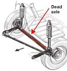
Fig Dead Axle in an automobile
Q20) Explain live axle suspension? Why unsprung weight associated with live axle is considered as evil?
A20)
Live axle Suspension
It is another type of a beam axle. It can be dependent suspension system or independent as well. In this design, shaft or shafts which are connected to work (move) as a single unit also transmits power to the wheels. As such apart from holding the wheels in proper position, it also drives them. The live axle is two half axles both combined with a differential with the help of universal joint. Each half of the axle is connected to its respective wheels using constant velocity joint (CV). The objective of this joint is to assist vertical and pivot motions of a wheel assembly. Live axle is very big and heavy. It consists of the differential, drive shafts, leaf spring and a tube enfolding all things. Since the whole axle is rigidly fixed to the wheels the Unsprung weight is very high. Without the driving mechanism incorporated, dead axle has much less unsprung weight, so its ride quality is better than a Live Axle.
Unsprung Weight Disadvantage
Unsprung weight is the part of the vehicle that is not riding on top of the suspension, likes the wheels, tyres etc. Unsprung weight is a highly undesirable attribute in suspension design, because with less amount of unsprung load the suspension is able to react faster to humps rather than simply transmitting the shock to the cabin.
The ratio of sprung to unsprung weight is a decisive factor in deciding how smoothly a car ride. A heavier car rides better than a lighter car? It is because the heavier car most likely has a higher sprung to unsprung weight ratio than the lighter car. This also means that lighter cars can be made to ride better than heavier cars if they manage to keep their unsprung weight down. And it also explains why these heavy off roaders still ride so roughly while handling so poorly compared to cars much lighter than them.
Compared to the latest independent suspension, a live axle system has the entire differential assembly, tubing and final driveshaft’s as unsprung masses although the main driveshaft is partly sprung. All current independent suspension has the final driveshafts partially unsprung and main driveshaft(s) and differential assemblies are sprung masses attached to the body. Thus, one can see how much of an unsprung weight penalty there is by using a live axle.
Q21) Write a short note on Air Suspension System?
A21)
Air Suspension
This is a type of vehicle suspension which is powered by pump or compressor. This pump or compressor can be engine-driven or electric driven. The compressor pumps the air into a flexible bellows, usually made from textile-reinforced rubber.
Unlike hydraulic suspension and hydro-pneumatic suspension, this system does not use pressurized liquid, but pressurized air. The air pressure created by the pump/compressor expands the bellows, and elevates the chassis from the axle.
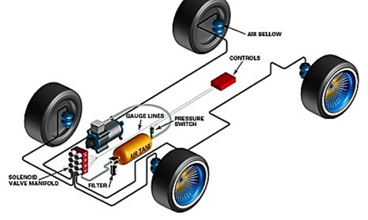
Fig 24 Air suspension System
Air suspension is used in place of conventional steel springs suspension in heavier automobiles i.e., as tractors, trucks, buses and in few passenger cars. It is extensively used on semi-trailers and trains i.e., principally passenger trains.
Q22) Discuss the role of shock absorber in Suspension System of an automobile?
A22)
Role of Shock Absorbers
A shock absorber is a device or component that is intended to engross (absorb) and dampen shock waves, impulses and vibration when the vehicle is moving. It is designed for absorbing or dampening the compression and rebound of the springs and suspension. It does this by converting the kinetic energy from the shock waves into heat energy generally, which is then dissipated.
Most shock absorbers are a form of dashpot (a damper which resists motion via viscous friction). They control the unwanted and excess spring motion. Shock absorbers keep your tires in contact with the road at all times which ensures the safest control and braking response from car.
They are generally classified in two forms:
- Mechanical Dampener
- Hydraulic Dampener
Typical dampers do not support the automobile, it is the spring that support the weight of the vehicle and these dampers control the compression and rebounding of the spring.
As a wheel rolls over a bump, the wheel moves toward the body and compresses the spring(s) of the vehicle. As the spring compresses, it stores energy. The spring then releases this stored energy, causing the body of the vehicle to rise (rebound).