Unit - 4
Electrical System and Fuel Supply System
Q1) What is Starter? Explain the working of Starting System.
A1)
- An automobile engine always needs some speed to start or work. A starter is an electrical unit whose function is to start the engine at its self-power.
- The starter consequently assists the engine to attain the preferred speed to drive the car.
- As the required speed is achieved, the starter shuts down.
- The location of this device differs based on the design and model of the automobile.
- Although most of them are normally located on the bottom of the vehicle behind the engine where the engine meets the transmission.
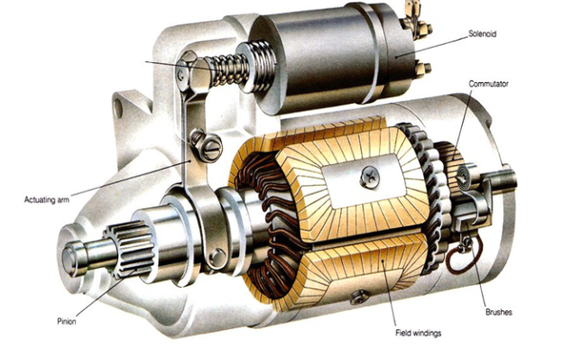
Starter of an Automobile
Working of a Starting System: -
- The main function of this device is assisting the engine to attain the preferred speed to drive the car.
- For doing this, this device makes use of the power which is received from the battery of the car.
- The battery is started using an ignition switch making the current to flow to the solenoid.
- The solenoid completes the ckt. And triggers the starter motor.
- The starter gear is then moved frontward. The gear is in mesh with the flywheel of the engine, and this flywheel is connected to the crankshaft.
- This crankshaft is rotated by the starter, starting the engine.
- After starting of the engine, the starter is shut off.
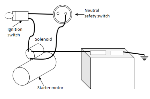
Working of Starting System.
Q2) Explain different types of Starting Motors (SMs) with diagram.
A2) Starter motors are of 5 types which are named as below:
1) Direct Drive
2) Planetary Gear
3) Permanent Magnet – Gear Reduction
4) Permanent Magnet – Direct Drive
5) Off-Set Gear Reduction (OSGR)
(1) DD – Direct Drive
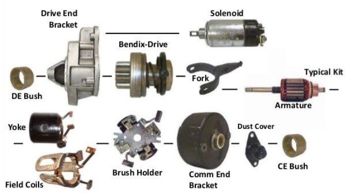
Direct – drive (DD).
- DD is the one of the simplest and commonly used SM types.
- DD is a solenoid operated device coming in variety of design.
- The operational principle of all solenoid driven SMs are the same.
- The solenoid is actuated by the control ckt of the battery as the ignition is switched to the ON position. The plunger turn rotates the shift lever.
- The lever then moves gear (pinion) which is in mesh with the engine flywheel.
- This causes the starter motor to spin. The spinning motion is transferred to the flywheel attached to the crank shaft, eventually rotating the engine until it runs on its own.
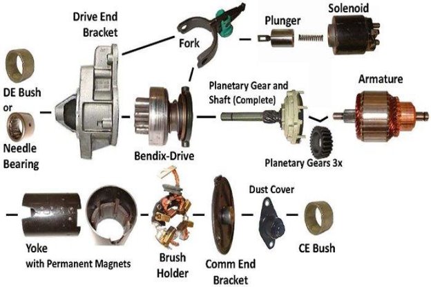
(2) PLGR – Planetary Gear.
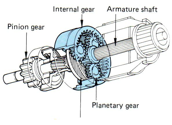
Planetary Gear (PLGR)
- PLGR forms the part of permanent magnet SMs that are quickly replacing DD motors.
- The PLGR motor transfers the power b/w the armature and shaft pinion enabling the armature to rotate at greater torque and speed.
- PLGR assembly contains a sun gear situated at armature end used for gear reduction and reducing current demand.
- 3 stationary plenary carrier gears are also located intimate the ring gear.
- The noteworthy point here is that, by holding the ring gear while outputting the carrier and inputting the sun gear, the planetary gear is capable of achieving a significant amount of gear reduction.
(3) PMGR-Permanent Magnet – Gear Reduction
Permanent Magnet Gear.
- The important specifications of this SM are lightness in weight, simple construction and low output in terms of heat.
- PMGR uses four to six magnet field assemblies.
- It is energized via a 12V solenoid which has three terminals and is heavy duty which allows it to draw less current.
- It does not have a field coil due to which the brushes and the commutator offers current directly to the armature.
- These SM should be precisely handled, particularly the permanent magnets as they are brittle and the cab gets damaged easily.
(4) PMDD-Permanent Magnet – Direct Drive
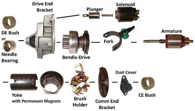
This SM type is comparable to the DD starter with the difference being that they use permanent magnets in place of field coils.
PMDD Starting Motor.
(5) OSGR Motor
- This SM type is manufactured for working at high speed and less current.
- It is very compact and light in construction and as such easily get assembled.
- OSGR also enhances the crank torque making it general use amongst the four-wheel drive vehicles.
- OSGR weight and compatibility makes it one of the supreme purchased SM for automobiles having high speed and cranking torque.
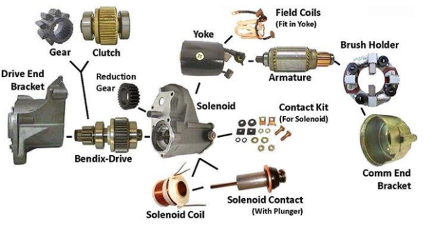
Offset Gear Reduction.
Q3) Define Dynamo or Generator. State the principle of generator.
A3)
- A generator or dynamo is a machine used for converting mechanical energy into electrical energy.
- As engine is powered, the generator generates electricity for running all the electrical circuits in the vehicle and at the same time keeps the battery charged.
Principle of Generator
"When a conductor placed in a magnetic field, a current is produced in that conductor. Fleming’s right-hand law is used to determine the current direction.
Fleming's right-hand rule: - If the thumb, index and middle finger are as such that they are perpendicular with each other, then the induced current direction of can be found by using below rule.
"If magnetic field and conductor motion is indicated by first finger and the thumb respectively, then the induced current direction is given by middle finger.
We all know the magnetic field acts b/w the magnets north and south poles. These poles are surrounded by the lines of forces. As the conductor makes movement cutting these force lines, the current gets generated in the conductor.
The generated current is used to drive different electrical components such as, battery, lightning system etc. The current induced depends on magnetic field strength and the rate at which the force lines intersect.
This working principle is given below in Fig.
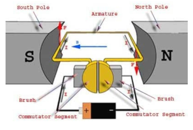
Working principle of generator
Current is induced, when the conductor (armature) is moved in the magnetic field. Due to opposite direction of motion of 2 legs, the current flow direction is also opposite in both conductor legs.
The two ends of the conductor are connected to the commutator (two split copper rings) and are connected to the external circuit via carbon brushes. Thus, the rotation of the armature generates current which can be used to drive the electrical system of an automobile.
The magnets used are electromagnets to which energy is supplied from the generator itself. The armature consists of a core, windings and an armature shaft.
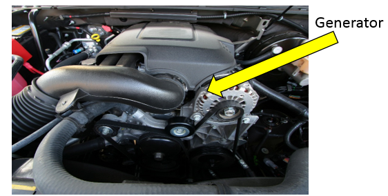
Automobile generator.
Q4) What is Regulator? How a regulator can regulate the current and voltage produced by the generator?
A4)
This device is used for controlling the current and voltage produced by the alternator. Current regulator (CR) or voltage regulator (VR) both can be present inside the automobile. In electrical system current regulator function is important.
In addition to regulating voltage, the current output (amps) of a generator is also called a current regulator.
The regulator is located in the voltage regulator and its working is similar to a voltage regulator.
The main difference is that this (current regulator) is made of thicker wire as compared to voltage type, and they also consist of fewer turns/ wraps of wire on the coil. The CR carries all the output current generated by the dynamo.
If the generator is rotating fast, the charge will be good, but many accessories will be on, then the VR will be functioning. As the generator is spinning slowly, the charging will be low, and if most accessories are on, then CR will be functioning.
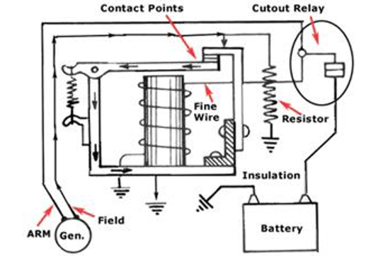
Regulator
An external resistance is provided for controlling the current and voltage. Resistance is connected across the field circuit as shown in Fig 4.10. It is connected between the field winding and the insulated brush.
The switch is closed until the voltage O/P is excessive. The switch field connects the outer end of the circuit to ground. If the voltage rises beyond the given limit, the switch is opened. This field brings resistance to the circuit. This reduces the current flowing in the field winding. The voltage also decreases.
Q5) Explain Lightning System and draw the circuit of a lightning system in an automobile.
A5)
A vehicle's lighting system contains signaling and lighting devices glued or joined to the vehicle's front, rear, sides etc.
This lights the road for the motorist and increases visibility of the vehicle, which allows other automobiles and walkers to see a vehicle's presence, size, direction of travel etc.
Emergency automobiles typically carries characteristic lighting units to notify drivers and direct priority of movement in traffic. Vehicle lighting systems are vital, particularly where road safety cares. If headlights were suddenly to fail in the dark and at high speed, the result might be catastrophic.
Many techniques are used, starting from automatic conversion circuits to thermal circuit breakers, that pulse the lights instead of golf stroke them out as a blown fuse would.
Modern wiring systems fuse each bulb filament separately and even if the main supply to the headlights failed, it is likely that dim-dip would still work.
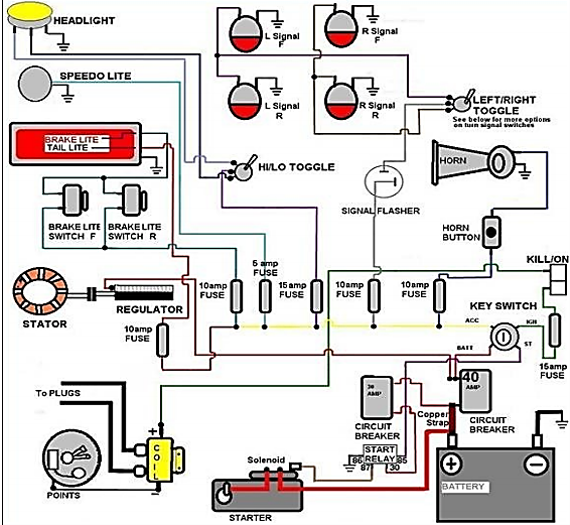
Lightning system of an automobile.
Q6) What is Ignition System? Write its function. Also explain various types of Ignition System.
A6)
- The Ignition System of an automobile or internal-combustion engine produces the spark for igniting the fuel-air mixture.
- It includes the battery, ignition coil and switch, distributor, spark plugs, and associated switches and wiring.
Functions of an IS:
- It produces volt spark of 30,000 V
- It transfers the spark to each spark plug.
- It times the spark so it occurs as piston is nearing TDC.
- IS also causes variation in timing of spark at different load and speed conditions.
Types of IS: -
- Battery ignition system
- Magneto ignition system
- Distributor less ignition system
(1) Battery Ignition System.
- A battery ignition system consists of a 6- or 12-volt battery that is charged by a generator powered by an engine to supply power, an ignition coil to raise the voltage, a device to interrupt current from the coil, a distributor to direct the current to the correct cylinder., and a spark plug is projected into each cylinder.
- Current travels from the battery through the primary winding of the coil, through the interrupting device, and back into the battery.
- The function of primary circuit components are given below:
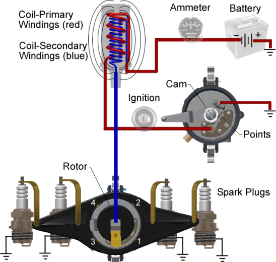
Battery Ignition System.
The functions of these components are:
- Battery - Provides power to run the system
- Ignition Switch - Allows the driver to turn the system on and off
- Primary Coil - Generates a magnetic field to create high voltage in the secondary coil.
- Breaker point - a mechanical switch that acts as a triggering mechanism
- Capacitor - protects the points from burning.
The secondary circuit converts the magnetic induction into high voltage electricity to cross the spark plug gap, firing the mixture at the right time. The functions of the components are –
- Secondary coil – the part of the coil that creates the high voltage electricity.
- Rotor – spin around on the top of the distributor shaft, and distributes the spark to the right spark plug.
- Spark plug – Take the electricity from the wires and give it an air gap in the combustion chamber to jump across to light the mixture.
(2) Magneto Ignition System.
- The simplest form of spark ignition is that using a magneto.
- An ignition magneto, or high-tension magneto, is a magneto that provides current for the ignition system of a spark-ignition engine, such as a petrol engine.
- The engine spins a magnet inside a coil, or, in the earlier designs, a coil inside a fixed magnet, and also operates a contact breaker, interrupting the current and causing the voltage to be increased sufficiently to jump a small gap.
- The spark plugs are connected directly from the magneto output.
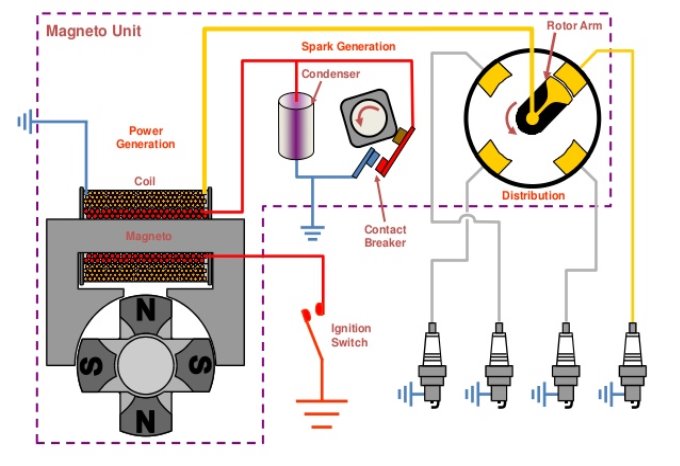
Magneto Ignition System.
(3) Distributor Less Ignition System.
- In operation the only major difference is that DI systems fire all of the engine’s spark plugs in ONE crankshaft revolution, whereas the old mechanical distributor type fires all plugs every TWO crankshaft revolutions.
- On all four stroke engines, equipped with or without distributors require TWO crankshaft revolutions (720° travel) for the combustion to occur on each cylinder. On engines with an even number of cylinders, combustion occurs in half of the cylinders in the first revolution (360°) and in the other half in the second half of the revolution.
- Each cylinder that has combustion in the first revolution has a companion cylinder that fires 360° apart from it during the second revolution.
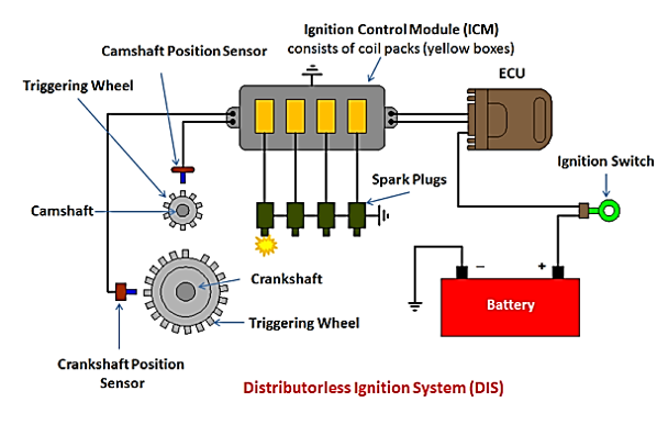
Q7) How a vehicle horn works. Explain in detail.
A7)
- A horn is a sound-making device that can be fitted to motor vehicles, buses, bicycles, trains, trams (otherwise known as streetcars in North America), and other types of vehicles.
- The sound made usually resembles "hon" (older vehicles) or "beep" (modern vehicles).
- The driver uses the horn to warn others about the movement or presence of a vehicle, or to call attention to a danger.
- In some countries, motor vehicles, ships and trains must have horns. Like trams, trolley cars and streetcars, bicycles are also legally required to have an audible warning device in many areas, but not universally, and not always a horn.
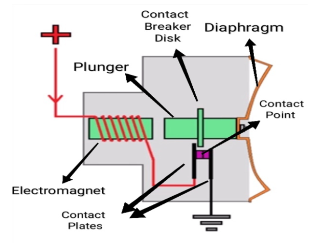
Horn of an Automobile.
Q8) What is automotive battery. Write its functions.
A8)
- Automotive battery is a rechargeable battery that provides electric current to a motor vehicle. Its main purpose is to feed the starter, which starts the engine.
- Once the engine is running, power is supplied to the car's electrical system by the battery with the alternator charging when demand increases or decreases.
- Typically, starting uses less than three percent of the battery capacity. For this reason, automotive batteries are designed to deliver maximum current for a short period of time.
- They are sometimes referred to as "SLI batteries" for starting, lighting and ignition. SLI batteries are not designed for deep discharging, and a full discharge can shorten the life of the battery.
Battery Functions
1. Engine off: Battery energy is used to operate the lighting and auxiliary systems.
2. Engine starting: Battery energy is used to operate the starter motor and to provide current for the ignition system during cranking.
3. Engine running: Battery energy may be required when the vehicle's electrical load requirements exceed those supplied by the charging system.
In addition, the battery also acts as a voltage stabilizer, or large filter, by absorbing abnormal, transient voltages in the vehicle's electrical system. Without this protection, some electrical or electronic components may be damaged by these high voltages.
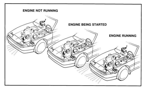
Functions of battery.
Q9) Explain the construction of automotive battery.
A9) Construction
1. Case: The container that holds and protects all battery components and electrolyte, separates the cells, and provides space at the bottom for sediment (active material washed off the plates).
2. Cover: Permanently sealed on the top of the case; Provides outlet for terminal post, vent hole for venting gases and outlet for battery maintenance (checking electrolyte, adding water).
3. Plates: The positive and negative plates have a grid structure of antimony and lead alloys. The active material is glued into a grid ... Brown lead dioxide (Pb02) on the positive plates, brown sponge lead (Pb) on the negative plates. The number and size of plates determine current capacity.
4. Separators: Thin, porous insulators (woven glass or plastic envelopes) placed between the positive and negative plates. They allow passage of electrolyte, yet prevent the plates from touching and shorting.
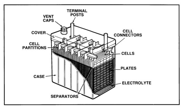
Parts of a battery
5. Cell: The combination of positive and negative plates connected with separators in the middle is called cell or element. When immersed in an electrolyte, a cell generates approximately 2.1 volts (regardless of the number or size of the plates).
6. Cell Connectors: Strips of heavy, cast alloy are welded to the negative terminal of one cell and the positive terminal of an adjacent cell until all six cells are connected in series.
7. Cell division: Part of the case, division separates each cell.
8. Terminal Post: Thick, heavy cables are attached to the positive and negative posts (terminals) on the case top. These cables connect the battery to the vehicle's electrical system (positive) and ground (negative).
9. Vent Caps: allows the controlled release of hydrogen gas during charging (vehicle operation). Removed, they allow to check the electrolyte and, if necessary, add water.
10. Electrolyte: A mixture of sulfuric acid (H2SO4) and water (H2O). It reacts chemically with the active material in the plates to create electric pressure (voltage). And, it conducts the electric current generated by that pressure from plate to plate.
Q10) Explain the fuel supply system in S.I. Engine or petrol engine. How many types of fuel supply system is used in an automobile?
A10) In a S.I engine, a measured quantity of petrol or gas is already mixed with air in a calculated proportion before being sucked by engine.
Then this combustible charge having right quantity of fuel-air is ignited at the appropriate time at the end of compression stroke in the engine with the help of a spark plug.
The operation of spark plug is timed along with the moment of crank shaft with the help of ignition system.
Depending on the method of mixing petrol or gas in the air in right proportion as per the requirement of engine, the fuel supply system of S.I engine is conventionally is of two types: -
(i) The first one is carburetion in which, fuel stored in the fuel tank is supplied to carburetor by means of a simple diaphragm pump through a fuel filter.
(ii) The second one is electronic fuel injection or MPFI system. In this system an electrically driven fuel pump draws fuel from fuel tank and supplies it to a common header or tube. A pressure regulator fitted at the end maintains a constant pressure of fuel approx. 3 bars in the header.
(1) Carburetor.
- In the carburetion method, fuel stored in the fuel tank is supplied to carburetor by means of a simple diaphragm pump through a fuel filter.
- The job of pump is only to supply fuel from fuel tank to float chamber of carburetor. Sometimes when the fuel tank is above the carburetor like in 2-wheeler engine, fuel will come by gravity and fuel pump is not needed.
- The design & working of a simple carburetor fitted in the suction line or Inlet manifold of engine is very simple.
- There is a venturi in the flow passage of air being sucked by engine.
- A jet is situated in the venturi and connected to the float chamber of carburetor, where fuel is stored at atmospheric pressure.
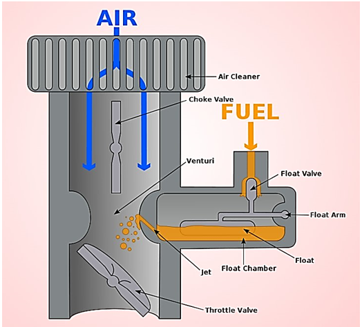
Carburetor
- The float keeps the fuel at a constant level in the float chamber. While passing through the venturi, pressure of air reduces and a pressure difference is created across the fuel jet connecting float chamber with venturi.
- Due to this pressure difference fuel is continuously supplied to air flowing through venturi.
- As jet is of very small inner diameter, fuel i.e., petrol is sprayed in the flowing air and due to its high volatility, it vaporizes and forms a combustible mixture of fuel vapour plus air.
- The fuel air ratio is automatically controlled by the speed of air through the venturi which eventually depends on speed/rpm of engine.
- The size of venturi and jet are designed on the basis of desired fuel air ratio.
- In an actual carburetor, some additional systems are there to satisfy the demands of engine under varying conditions like cold starting, engine idling, requirement of additional power at high speed & load etc.
- Ambient temperature
- Inlet manifold vacuum or Air Velocity
- Exhaust gases temperature
- Exhaust O2content
- Throttle position
- Engine r.p.m.
- Crankshaft & position
- Engine coolant temperature
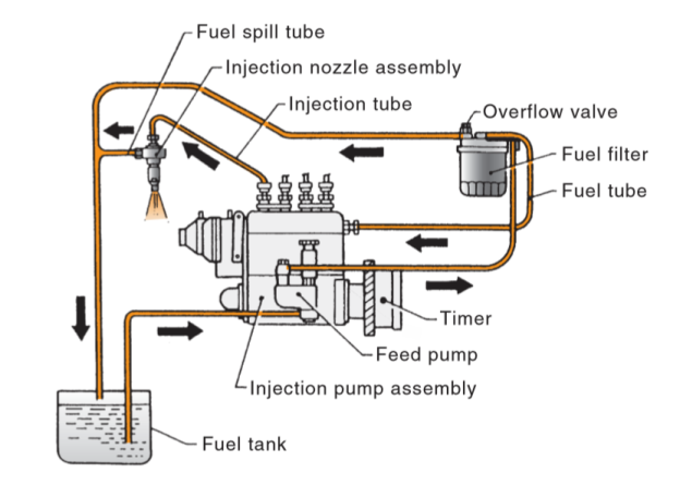
- This system was universally being used in Diesel Engines until the introduction of new fuel injection technology like CRDI etc. But still due to the reason of more initial cost involved in adopting newer technology, it is being used in Diesel Engines of different sizes.
- In this type, there are two basic components as one pressurizing unit (High Pressure Pump) and other atomizing unit (High pressure nozzle or injector).
- Individual pump and injector system
- Common rail system
- Distributor system
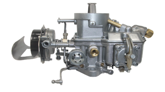
Carburetor of a vehicle
(2) Multi – Point Fuel Ignition System (MPFI)
In this system an electrically driven fuel pump draws fuel from fuel tank and supplies it to a common header or tube. A pressure regulator fitted at the end maintains a constant pressure of fuel approx. 3 bars in the header.
The header is connected to different branches of inlet manifold through fuel injectors. For each cylinder of engine there is separate fuel injector which injects fuel in the corresponding air passage of that cylinder.
Due to this the system is called multi-point fuel injection (MPFI) system.
The fuel injectors are precision built solenoid valves having single or multiple orifices.
MPFI System
An on-board ECU (Electronic control unit) i.e., microprocessor controls the quantity of fuel injected to each cylinder individually and also the ignition timing of each cylinder. The data input to the ECU comes from a number of sensors located all over the engine. These sensors collect the following data continuously.
Due to constant pressure of fuel maintained in the common header, the quantity of fuel injected depends only on the time period for which the solenoid valve type fuel injectors are kept in open position.
Based on programmed interpretation or processing of this data, ECU calculates the amount of fuel needed to maintain stoichiometry i.e., air/fuel ratio of 14.7:1 and converts it into required pulse width i.e., time period for which it keeps the solenoid injector energized.
ECU also gives command to spark ignition system. In this way ECU ensures overall satisfactory performance of the engine from start to shut down including emission control by sending right quantity and quality of fuel air mixture to each cylinder of engine at right time based on requirement of engine and also ignites it at right time.
Q11) Explain the fuel supply system in C.I. Engine or diesel engine. Also explain the different type of diesel injection system.
A11) The primary requirement of a C.I engine is to inject the right quantity of fuel at a very high pressure either directly over the piston in the cylinder of engine or indirectly in a combustion chamber in the cylinder head which is connected to cylinder of engine.
In any method the fuel injection system has to control injection timing, injection period and injection pressure. Now in most of the diesel engines direct injection is used with improved injection technology.
The diesel injection systems used nowadays are of two types:
1) Mechanical Injection System
2) Electronic Injection System
(1) Mechanical Injection System
Depending on the design, manner of operation and control of these two basic components, mechanical fuel injection system are of three types: -
(i) Individual pump and injector system
In this system there is a separate pump and separate injector for each cylinder of engine. The pump creates high pressure of fuel and also meters and times the injection of fuel through injector. It is a plunger type pump driven by engine power itself.
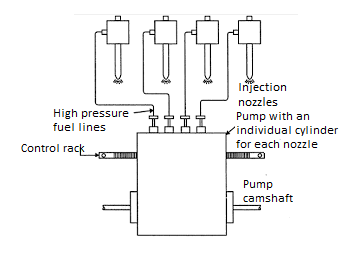
Individual Pump and Injector System
(ii) Common Rail System
- Here a high-pressure pump keeps constant high pressure of fuel in an accumulator with the help of a pressure regulating valve.
- This accumulator is connected to common rail which is extended to different distributing elements of each cylinder.
- A separate metering & timing element controls the supply of metered & timed pressurized fuel to each injector of cylinder.
- This system is self governing and more smooth operation is there.
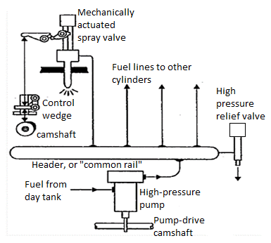
Common Rail System
(iii) Distributor System
Like the first system, here also the pump pressurizes, times and meters the fuel. But which quantum of fuel is to be supplied to which injector, is decided by a rotating distributor. This system is cheaper than first system in case of a multi-cylinder engine.
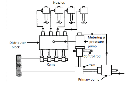
Distributor System
(2) Electronic Injection System (with CRDI technology used).
- In this system of diesel injection, a common rail diesel injection (CRDI) technology is used.
- It is more or less same as Common Rail System of Mechanical Injection but the difference comes in the control over metering & timing of injectors which is done by an on-board computer system or electronic control unit.
- There is a high pressure fuel pump which maintains high pressure in a common rail (steel tube) through high pressure regulator.
- But here the pressure maintained is very high of the order of 2000 bar as compared to 3-5 bars in MPFI system.
- The fuel injectors are very special either solenoid type or piezo electric type which control the fuel injection from common rail to each cylinder very precisely.
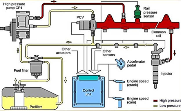
Electronic Injection System.
- The opening time, pulse width etc. of fuel injectors can be electrically controlled by the E.C.U. Here is the main advantage of system that the fuel can be injected in more than one pulse in a very controlled manner unlike only one pulse or one injection per cycle in the mechanical system.
- A pilot injection is done before the main injection for fast burning and less ignition delay of the fuel.
- It reduces the noise level very much and also ensures complete burning of fuel, high efficiency, low emission and good cold start.
- This new technology has considerably removed the demerits of diesel engines like high noise level, high pollution, difficulty in starting etc. and improved fuel efficiency a lot.
Q12) What is injector pump? Explain in detail.
A12)
- An injection pump is a device that pumps diesel (as fuel) into the cylinders of a diesel engine.
- Traditionally, the injection pump is driven indirectly from the crankshaft by a gear, chain or toothed belt (often the timing belt) which also drives the camshaft.
- It rotates at half the crankshaft speed in a conventional 4 – stroke diesel engine.
- Its timing such that the fuel is injected long before the top dead center of compression of that cylinder’s C.R.
- It is also common for the pump belt on gasoline engines to be driven directly from the camshaft. Injection pressure can be up to 620 bar (8992 psi) in some systems.
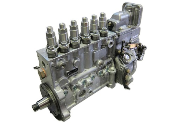
Injector Pump.
Q13) What is fuel injector. Explain with the help of diagram.
A13)
- A modern fuel injection system technically includes a sensing mechanism that determines the exact amount of fuel that needs to be sprayed into the engine's intake manifold.
- Another mechanism is needed to distribute or spray the calculated amount of fuel into each cylinder.
- Fuel injectors are the parts of modern car engines that directly or indirectly deliver fuel into the combustion chamber of the engine.
- These small electro-mechanical devices are usually located at a certain angle to ensure that fuel is sprayed toward the engine's inlet valve or directly into the cylinder.
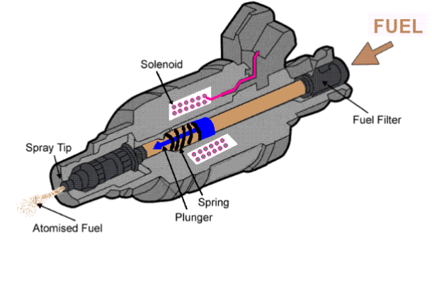
Fuel Injector