Unit – 3
Equation Of Motion for Laminar Flow Through Pipes
Q1) What is Flow Resistance?
A1) Consider the water flow from one reservoir to the next, as depicted in Fig. The water levels in the two reservoirs A and B are kept constant. The distinction between these two levels is depicted in the diagram. Water flows from reservoir A to reservoir B as a result.
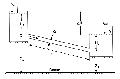
Applying Bernoulli's equation


 is the loss of head
As a result, the equation above states that in a steady state, the head causing flow equals the total head loss due to the flow.
The overall loss of head can be described in terms of its multiple components, taking into account probable hydrodynamic losses.

Where first term is Loss of heat at entry to the pipe from reservoir A, second Friction loss in pipe over its length L and third Exit loss to the reservoir B and where, V is the average velocity of flow in the pipe. Because the flow rate remains constant throughout the pipe even if its diameter changes in steady state, the velocity V in the preceding equation is commonly substituted in terms of flow rate Q.

We finally get


The term R is defined as the flow resistance
When f is independent of Re, the flow resistance is just a function of the pipe geometry. Eqn can be written as follows:

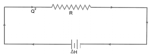
In Eq, H is the head that causes the flow and is defined as the difference between A and B's flow potentials. In a purely resistive electrical circuit, this equation is analogous to the voltage-current relationship. In an electrical circuit that is solely resistive,  where
where  is the voltage or electrical potential. However, while the voltage drop in an electrical circuit is proportional to the current, the difference in the flow potential in a fluid circuit is proportional to the square of the flow rate.
Therefore, Fluid System can be described as network
Q2) What is Boundary layer Thickness, Displacement thickness Momentum Thickness and shape factor for velocity profile?
A2) Boundary layer thickness
The thickness of the boundary layer is a function of the coordinate direction x. When compared to the domain's typical length L, the thickness is deemed to be quite modest. Within this thin layer, the gradient in the normal direction is much larger than the gradient in the flow direction  . It is the distance from the boundary to the point where velocity of fluid is approximately equal to 99% of free stream velocity (U).
It is denoted by ' '
'

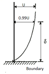
Although the notion of boundary layer thickness is somewhat arbitrary, displacement thickness is a physically more meaningful metric of boundary layer estimation
Displacement thickness : The distance by which the exterior potential flow is shifted outwards due to the decrease in velocity in the boundary layer is known as displacement thickness.

Momentum thickness : It is defined as the difference in momentum between the boundary layer and potential flow.

Shape factor: The shape factor H is the ratio of displacement thickness to momentum thickness.

Q3) Explain the drag on sphere.
A3) The Drag force Equation is given by,
Drag force, 
Where FD is same to the drag, rho is the air density, U is the velocity, A is a reference area, and CD is the drag coefficient.
Consider the flow of a real fluid past a sphere.
Let
U = Velocity of the flow of fluid over sphere,
D = Diameter of sphere,
p = Mass density of fluid, and
μ = Viscosity of fluid.
If the Reynolds number of the flow is very small less than 0.2 i.e.,  , The viscous forces are significantly more relevant than the inertial forces, as viscous forces are much more dominant than inertial forces, which can be assumed to be negligible in this situation. G.G. Stokes devised a mathematical equation for the total drag on a sphere immersed in a moving fluid with a Reynolds number of up to 0.2, allowing for minimal inertia forces.

Also, Skin Friction Drag is two- third of FD, that is equal to) 
NS pressure drag is 1/3 that is 
- Value of CD on Sphere when Re<0.2


This is also called as stokes law
2. Value of CD on Sphere when Re between 0.2 and 5
The inertia forces grow as the Reynolds number rises, therefore they must be considered. Oseen, a Swedish physicist, improved Stoke's law when R is between 0.2 and 5.

This is called Oseen formulae and is valid for R, between 0.2 and 5.
3. Value of CD on Sphere when Re between 5 to 1000.
For Reynolds numbers ranging from 5 to 1000, the drag coefficient is 0.4.
4. Value of CD on Sphere when Re between 1000 to 100,000
CD is independent of Reynolds number in this range, and its value is about equivalent to 0.5.
5. Value of CD on Sphere when Re is more than 105.
For Reynolds numbers greater than 105, the value of C is roughly equivalent to 0.2.
Q4) Write examples of viscous flow and explain the characteristics of Laminar flow.
A4) Viscous flow is defined as a fluid flow in which frictional effects become significant. Frictional force develops between two fluid layers when they move relative to each other, which is measured by the fluid attribute 'viscosity.' Viscous flow is exemplified by boundary layer flows. The flow can be considered as inviscid if the viscous elements in the governing equation are ignored.
Examples: Honey, Toothpaste, Motor oil
Characteristic of Laminar Flow
- Smooth streamlines and highly organised motion describe laminar motion. For Re 2000, the flow in a circular pipe is laminar under most practical conditions.
- Each fluid particle moves at a constant axial velocity along a streamline in fully developed laminar flow, and the velocity profile remains unchanged in the flow direction.
- In the fully developed region of a straight circular pipe, the steady laminar flow of an incompressible fluid has constant characteristics.
- The relative motion of a set of concentric cylinders of fluid in a straight pipe can be thought of as the relative motion of a set of concentric cylinders of fluid, the outside one fixed at the pipe wall and the others moving at increasing rates as the pipe centre is approached.
- Laminar flow occurs only when the flow channel is tiny, the fluid moves slowly, and the viscosity of the fluid is relatively high.
Q5) What is flow separation?
A5)
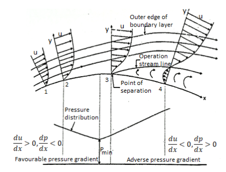
Effect of pressure gradient on boundary layer surface:
Consider steady flow and apply boundary condition at the solid boundary where y = 0, u = 0.
∴
Depending upon the curvature the boundary, there are three possible cases.
1)There is gradual increase in velocity and drop in pressure as the flow passes from 1 to 2 i.e., pressure drop in the direction dp of flow,  <0. The entire boundary layer moves forward, till the pressure gradient less than zero. This condition is called as favourable pressure gradient.
2)The flow retards and pressure increase as flow passes downstream from section 2. This condition is called as adverse pressure gradient. Both pressure and shear force produced continuous retardation in the flow momentum and a stage Coolness when the momentum of the fluid is unable to overcome the surface resistance. It is developed near the curved du surface where velocity gradient  = 0 i.e., at section 3. This dy point at which the boundary layer is on the verge of separation from the surface is called as point of separation.
3)The fluid separated from the surface due to continuous retardation of flow. It has tendency to flow in a direction opposite to the main flow. It occurs beyond the point 3. Where  >0
>0
Location of separation point:
For the given velocity profile, there are three conditions for location of separating point:
1)If  is positive, the flow will remain attached with the surface.
2) If  is zero, the flow is on the verge of separation.
3) If  is negative, the flow is separated.
Q6) What are the Magnus effects?
A6)
- Magnus effect, technology of a sidewise pressure on a spinning cylindrical or round stable immersed in a fluid (liquid or gas) whilst there may be relative movement among the spinning frame and the fluid.
- Named after the German physicist and chemist H.G. Magnus, who first (1853) experimentally investigated the impact, it's far answerable for the “curve” of a served tennis ball or a pushed golfing ball and influences the trajectory of a spinning artillery shell.
- A spinning item transferring via a fluid departs from its instantly course due to stress variations that increase with inside the fluid because of pace adjustments caused via way of means of the spinning frame.
- The Magnus impact is a selected manifestation of Bernoulli’s theorem: fluid stress decreases at factors wherein the rate of the fluid increases. In the case of a ball spinning via the air, the turning ball drags a number of the air round with it.
- Viewed from the location of the ball, the air is speeding via way of means of on all sides. The drag of the aspect of the ball becoming the air (into the course the ball is traveling) retards the airflow, while on the opposite aspect the drag accelerates the airflow.
- Greater stress at the aspect wherein the airflow is bogged down forces the ball with inside the course of the low-stress place on the alternative aspect, wherein a relative growth in airflow occurs.
Magnus Force
When we consider a rotating ball that is likewise rotating in a cross-flow, the force is now exerted to the body that is perpendicular to the trajectory. We can figure out in which direction or angle the ball will deviate, because according to Thomson, a spinning ball is only supposed to deflect in the direction in which the ball's "nose" is turning. With this knowledge, we may conclude that in a projectile motion of a ball, the ball travels the most distance when rotated nose up to the ground, and the shortest distance when rotated nose down to the earth.
- Effect of Surface on Magnus Force
A cylinder with a smooth surface can produce Magnus effect, although it produces less Magnus effect than a cylinder with a rough surface. The concept of rough surface (dimples) was created in the early twentieth century to support this viewpoint. The roughness affects the flow of the boundary layer. The surface of a golf ball, for example, is dimpled. The shift to turbulent flow caused by these dimples minimizes drag.
- Negative Magnus effect
The aerodynamic features that affect a Magnus rotor are the circumferential speed of the rotor and the free stream velocity. One of the researchers, Lafay, discovered a secondary force that works in the opposite direction of Magnus' conclusion. At low velocity ratios, the negative Magnus effect can be seen at various Reynolds numbers. This effect is also influenced by the cylinder's surface. Negative Magnus force is a major worry for rotor planes because it can destabilize the aircraft by compromising the lift force.
- Magnus Effect on Cylinder
Mathematical representations can be used to demonstrate the Magnus effect. In a frictionless flow, R0 is the radius of the cylinder. The pressure can be calculated using Bernoulli's equation.

On Top side,

On Bottom side,

Difference

Pressure Across cylinder

On the top of the cylinder, the pressure is lower. The irrotational pressure (Magnus effect) on the cylinder is given by the side of the vertical lines passing through the cylinder's centre in our final equation.
Q7) What is Water Hammering?
A7) Consider a lengthy pipeline AB that is connected to the opposite side of a tank and contains water at a height H from the pipe's centre. A flow control valve is installed at the pipe's outermost end.
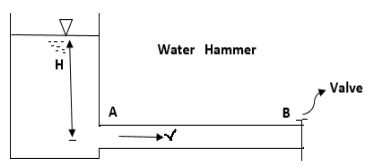
- Water flows at a velocity, V, in the pipe when the valve is fully open.
- A high-pressure wave interrupts the water flow if the valve is now closed.
- This high-pressure wave will travel through the pipe at the same speed as the sound wave, resulting in a knocking noise.
- The consequence of this high-pressure wave is to move the pipe walls, hence the name water hammer.
- The velocity of water flowing through the pipe, (ii) the length of the pipe, (iii) the time it takes to close the valve, and (iv) the elastic characteristics of the pipe's material all contribute to the pressure rise induced by water hammer.
- Head of pressure is given by =

- Time Taken by Pressure Wave to Travel from the Valve to the Tank and from Tank to the Valve if t is the required time taken by pressure wave, L is Length of the pipe, C is Velocity of pressure wave then total distance = L + L = 2L
- Time= Distance/ Velocity of pressure wave or

- If T is time taken to close the valve, The closure is Gradual if
 ,
, - The closure is not gradual if
 , C is velocity pressure and T is Time in sec.
Q8) A horizontal pipe of diameter 450 mm is suddenly contracted to a diameter of 200 mm. The pressure intensities in the large and smaller pipe is given as 13.734N/cm2 and 11.774 N/cm2 respectively. Find the loss of head due to contraction if Cc=0.62. Also determine the rate of flow of water.
A8) To find the head loss due to contraction,
Diameter of large pipe


Diameter of small pipe


Pressure in large pipe and small pipe


The head loss due to contraction,


By continuity equation,


Applying Bernoulli's equation, (Z1=z2)

Also


Substituting values


Q9) A horizontal pipeline 40m long is connected to a water tank at one end and discharges freely into the atmosphere at the other end. For the first 25 m of its length from the tank, the pipe is 250 mm diameter and its diameter is suddenly enlarged to 400 mm. The height of the water level in the tank is 8 m above the centre of the pipe. Considering all losses of head which occurs, determine the rate of flow. Take f=0.01 for both sections of the pipes.
A9) Given:
Total length of pipe, L=40m
Length of first pipe, L1=25m
Diameter of first pipe, d1=150mm=0.25m
Length of second pipe, L2=40−25=15m
Diameter of second pipe, d2=400mm=0.40m
Height of water, H=8m
Coefficient of friction, f=0.01
Applying Bernoulli's Theorem,


Where, loss at entrance

Head lost due to friction in pipe 1,

Loss due to sudden enlargement,

Head lost due to friction in pipe 2

But continuity equation,


Substituting the values of V1V1 in different losses, we get


Put the values in equation, we get


Therefore the rate of flow,


Q10) The rate of flow of water through a horizontal pipe is 0.25m3/s. The diameter of the pipe which is 150 mm is suddenly enlarged to 200 mm. The pressure intensity in the smaller pipe is 11.772N/cm2 Find Loss of head due to sudden enlargement, Pressure intensity in large pipe, Power lost due to enlargement.
A10)
Given:
Discharge, 
Diameter of smaller pipe


Diameter of larger pipe


Pressure in smaller pipe,


Loss of head due to sudden enlargement


Let pressure intensity in large pipe = P2

Since z1=z2


Putting values in equation (2), we get


Power lost due to sudden enlargement


Q11) Find the loss of head when a pipe of diameter 200 mm is suddenly enlarged to a diameter of 400 mm. The rate of flow of water through the pipe is 200 lit/s.
A11)
Given:


Diameter of small pipe


Q12) A 30 cm diameter pipe conveying water, branches into two pipes of diameters 20 cm and 15 cm respectively. If the average velocity in the 30 cm diameter pipe is 2.5 m/s, find the discharge in this pipe. Also determine the velocity in 15 cm pipe if the average velocity in 20 cm diameter pipe is 2 m/s.
A12)
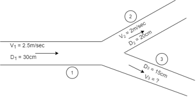
Given:


V1=2.5 m/s
V2=2 m/s


Let Q1, Q2, Q3 be discharges in pipe 1,2,3 respectively
According to Continuity equation
Q1= Q2 + Q3


Discharge Q3 = =
=
Q3
Q13) Determine the displacement thickness, momentum thickness, shape factor and energy thickness of the following velocity profiles in the boundary layer on a flat plate. u/U0 = (y/δ)1/7 where u is the velocity at a height y above the surface and U0 is the free stream velocity.
A13) Displacement Thickness


Momentum Thickness


Shape Factor

Energy Thickness


Q14) A fluid of viscosity 0.7 Ns/m2 and specific gravity 1.3 is flowing through a circular pipe of diameter 100 mm. The maximum shear stress at the pipe wall is given as 196.2 N/m2, find (i) Pressure gradient, (ii) Average velocity and, (iii) Reynolds number of the flow
A14)
Given:
Viscosity, 
Specific gravity, SP =1.3
Density = Sp  1000 =1300 kg/m3
Diameter of pipe, D=100 mm = 0.1 m
Shear stress,  = 196.2 N/m2
Shear stress is also given by


Pressure Gradient = - 7848 N/m2
Maximum Velocity is given by


Average Velocity is given by 


Reynolds Number


Q15) A square flat plate of dimension 1.5 m moves at 50 km/hr in stationary air of density 1.15 kg/m3. If the coefficient of drag and lift are 0.15 and 0.75 respectively, determine the lift and drag force.
A15)
Given:
Plate Area =side  side=1.5
 1.5 =2.25m2
Velocity 
Density 
Coefficient of Drag  is 0.15
Coefficient of lift is,  0.75
0.75
Drag Force


Lift Force


Resultant Force
