Unit – 4
Introduction to Hydrodynamic Thrust of Jet
Q1) How will you classify the turbines?
A1) Classification of turbines
Hydraulic turbines are classed based on the type of energy available at the turbine's intake, the direction of flow through the vanes, the head at the turbine's inlet, and the turbine's specific speed. As a result, the important classes of turbines are as follows:
1. According to the type of energy at inlet:
(a) Impulse turbine,
(b) Reaction turbine.
The turbine is known as an impulse turbine if the only energy available at the turbine's inlet is kinetic energy. From the turbine's inlet to outlet, the pressure is atmospheric as the water runs over the vanes. The turbine is known as an reaction turbine if both is kinetic energy and potential energy is available at the turbine's inlet.
2. According to the direction of flow through runner:
(a) Tangential flow turbine,
(b) Radial flow turbine,
(c) Axial flow turbine,
(d) Mixed flow turbine.
Tangential flow turbines are those in which the water flows along the tangent of the runner. Radial flow turbines are those in which the water flows in a radial direction via the runner. The turbine is known as an inward radial flow turbine if the water flows radially from outwards to inwards; on the other hand, the turbine is known as an outward radial flow turbine if the water flows radially from inside to outwards. A axial flow turbine is one in which the water flows through the runner in a direction parallel to the runner's axis of rotation. The turbine is called a mixed flow turbine when the water flows through the runner in a radial direction but leaves in a direction parallel to the runner's axis of rotation.
3. According to the head at the inlet of turbine:
(a) High head turbine,
(b) Medium head turbine,
(c) Low head turbine.
4. According to the specific speed of the turbine:
(a) Low specific speed turbine,
(c) High specific speed turbine.
(b) Medium specific speed turbine
Q2) What is meant by geometric, kinematic and dynamic similarities? Are these similarities truly attainable? If is not why?
A2) The notion of similarity underpins dimensional analysis as a whole. For perfect likeness between a model and a prototype, three conditions must be met.
Geometric similarity: The model must have the same shape as the original, although it can be scaled up or down by a constant factor.
Kinematic similarity: The velocity at any point in the model flow must be proportional to the velocity at the homologous point in the prototype flow by a constant scaling factor. (In other words, the flow streamlines must be identical in shape.)
Dynamic similarity: All forces in the model flow must scale to the equivalent forces in the prototype flow by a constant factor. In other words, for the model and prototype, the relative importance of different types of forces (e.g., viscous and inertial forces) must be the same.
This necessitates that the model and prototype have the same dimensionless parameters (e.g., the same Reynolds number), despite the fact that the dimensional variables may (and generally do) differ. For every p pi groups that can be specified mathematically for two different flow circumstances, dynamic similarity requires that
k, model k, prototype, k=1…….. p
As a result, while geometric and kinematic similarities are required, they are not sufficient for dynamic similarity. That is, geometric and kinematic similarities are attainable, but dynamic similarity is not.
Q3) Define the term governing of turbine. Describe with neat sketch the working of an oil pressure governor.
A3) It is generally done by oil pressure governors as shown in the figure below.
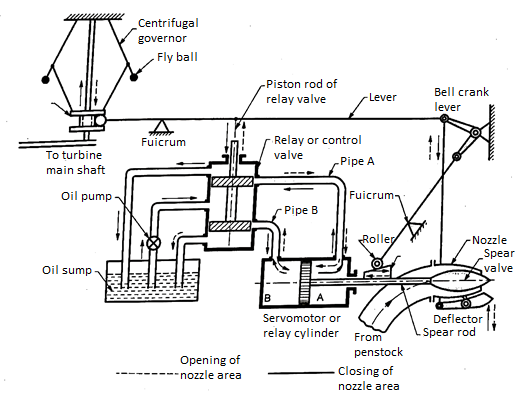
The major components of the governor mechanism are:
- Oil pump and oil sump
System uses oil in servo motor or relay cylinder since the force required to actuate the spear valve would be enormous. For this reason, the system requires an oil sump to store the oil and an oil pump to regulate the oil supply in the mechanism. Oil pump is a positive displacement type of pump like gear pump or axial piston pump. Its function is to pressurize the oil.
2. Relay or control valve
Relay valve is a spool valve having 5 ports. It is also called as control valve or distributor valve. It receives the pressurized oil from the oil pump which is diverted towards the ports connected to pipe A or pipe B. Through these pipes the oil is transferred to corresponding sides of double acting servo motor cylinder. Simultaneously, the oil will be returned from the servomotor from the opposite pipe to the sump.
3. Servo Motor or relay cylinder
It is a double acting cylinder which acts as hydraulic actuator. It receives oil from relay valve say through pipe A. The piston of the cylinder will be displaced towards left, thus forcing the oil through the pipe B into the relay valve and finally to oil sump. It will simultaneously more the spear valve to the left and increase the area of flow through the nozzle.
4. Spear valve
Spear valve controls the flow area of the nozzle. It is directly connected to the piston of relay cylinder.
5. Governor and linkages
A centrifugal governor is used as the measuring element of the closed loop control system. It is driven by the turbine shaft through bevel gears. The sleeve of the governor is connected through linkages to relay valve. The movement of sleeve is transferred through the lever to more the piston rod of relay valve.
Working
Figure above shows the position when the turbine is running at normal speed.
Consider the case when the load on the generator increases, the speed of the generator and that turbine will decrease. Since the governor is driven by the turbine shaft, its speed will also decrease. As a consequence, the flyball of the governor will move inwards due to reduced centrifugal force on the balls. As a result, the sleeve of the governor will move downwards.
The downward motion of the sleeve will be transferred to the main lever through its fulcrum. It will cause the piston rod of the relay valve to move upwards and simultaneously the bell crank lever also moves upwards. The upward motion of piston rod of control valve causes pressurized oil to flow through the pipe A to the relay cylinder and exerts a force on face A on the piston of servomotor. It moves the piston to the left, thus the spear rod with its valve will also move towards the left. It will increase the nozzle area and the rate of flow of water to the turbine increases. Therefore, the input to turbine and consequently its speed increases. During this piston movement of servo motor to the left, oil held in the cylinder towards the face B is transferred through pipe B to the oil sump via the relay valve. When the speed of turbine is adjusted to normal speed, the system would return to its original position. Opposite will be action of the whole mechanism when the load on the generator decreases. The increase in speed of turbine and generator will increase the speed of the governor. The balls flyout and the sleeve moves upwards. It causes the piston rod of relay valve to move downwards, thus opening the valve towards pipe B. Pressurized oil flows into servo motor cylinder towards the face B and causes the spear to move towards right thus closing the nozzle area. The reduced discharge to turbine runner reduces the input, hence its speed. When the speed attained by the turbine is its normal speed, the governing mechanism will return to its original position
Q4) With the help of neat sketch explain the working of Kaplan turbine.
A4)
- It is an axial flow turbine, which is suitable for relative low heads and hence requires a large quantity of water to develop large amount of power.
- As shown in figure the main component of Kaplan turbine are scroll casing, stay ring arrangement of guide vanes and the draft tube.
- Scroll Casing
It's a spiral-shaped casing with a smaller cross section area. Water from the penstocks enters the scroll casing, then runs axially through the runner into the guide vanes, where it spins 90 degrees. It shields the turbine's runner, runner blades, guiding vanes, and other internal components from external damage.
- Guide Vane Mechanism
It is the only portion of the turbine that controls the opening and closing of the blades in response to the demand for power. When more power is required, it opens wider to allow more water to hit the rotor's blades, and when less power is required, it closes to stop the flow of water. The turbine will not run efficiently if the guide vanes are missing.
- Draft Tube
The pressure at the exit of a Reaction Turbine's runner is usually lower than air pressure. The water near the exit cannot be released directly into the tail race. Water is discharged from the turbine exit to the tail race through a tube or pipe with a gradually increasing area. Draft Tube is the term given to this expanding tube. The tube is attached to the runner's output on one end and submerged below the water level in the tail-race on the other
- Between guide vanes and the runner the water in Kaplan turbine turns through right angle into axial direction and then passes through the runner.
- The runner of a Kaplan turbine has 4 or 6 blades.
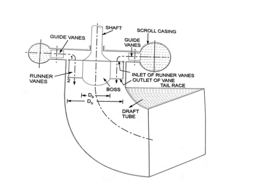
- The blades attached to a hub for boss are so shaped that water flows axially to the runner.
- Ordinarily the runner blades of propeller turbines are fixed, but the Kaplan turbine runner blades can be turned about their own axis, so that their angle of inclination maybe adjust while the turbine is in motion.
- The adjustment of the runner blades is usually carried out automatically by means of servomotor operating inside the hollow coupling of turbine and generator shaft.
- When the vanes are fixed to the hub and are not adjustable, the turbine is known as propeller turbine.
Working
The water coming from the pen-stock is made to enter the scroll casing. The scroll casing is made in the required shape that the flow pressure is not lost. The guide vanes direct the water to the runner blades. The vanes are adjustable and can adjust itself according to the requirement of flow rate. The water takes a 90 degree turn, so the direction of the water is axial to that of runner blades.
As the water strikes, the runner blades begin to revolve due to the water's reaction force. The runner blades twist along their length to maintain an optimal angle of attack for all cross sections of the blades, resulting in increased efficiency. The water enters the draft tube from the runner blades, where its pressure energy and kinetic energy are reduced. The conversion of kinetic energy to pressure energy leads in a rise in water pressure. The turbine's spin is utilized to turn the generator's shaft, which produces electricity.
Q5) Define Unit Quantities and Specific Speed. A turbine is to operate under a head of 30 m at 200 rpm. The discharge is 10 cumec. If the efficiency is 92%, determine: Specific speed of the machine, Power generated.
A5) Unit speed
The speed of a turbine operating under a unit head is defined as this (i.e., a head of 1 m). It is indicated by the letter N. The following is the expression for unit speed (N):
N = Nu √H Or Nu = N /√H
Unit discharge
It is the discharge that passes through a turbine that is operating under a unit head (i.e., 1m). The letter 'Q' stands for it. The unit discharge expression is as follows:
Q=Qu √H or Qu= Q/ √H
Unit power
It is defined as the power developed by a turbine, working under a unit head (i.e., under a head or 1 m ). It is denoted by the symbol 'P. The expression for unit power is obtained as:
P= Pu H³/2 or Pu= P/ H³/2
Specific Speed
It is described as the speed of a turbine that is similar to the actual turbine in shape, geometrical dimensions, blade angles, gate opening, and so on, but is of a size that produces unit power when working under unit head.

Given:
Head, H = 30 m
Speed, N = 200 rpm.
Discharge. Q =10 cumec = 10 m³/s
Efficiency, no = 92% = 0.92
Now using relation.
(i) P= Power developed or shaft power.


(ii) Specific Speed of Turbine


Q6) A single jet pelton turbine operates a 10,000 kw generator. The generator efficiency is 92%, turbine efficiency is 86%, turbine head is 350 m, coefficient of nozzle velocity is 0.98, speed ratio is 0.46 and jet ratio is approximately 12. Find the size of jet, mean diameter of runner, synchronous speed, specific speed of turbine and bucket dimensions.
A6)
Given
P₁ = 10000 kW,
Cv = 0.98,
ngen = 0.92, nturbine = 0.86,
H = 350 m,
Speed ratio, K = 0.46= u / V₁
Jet ratio, m= D/d = 12
Velocity of jet, V₁ = Cv  =
=  = 81.21 m/s
K = 0.46= u / V₁
Bucket velocity, u=0.46 x 81.2 = 37.36 m/s.
1. Jet diameter, d:
Overall efficiency, no= nturbine x ngen =0.86 x 0.92 = 0.7912


Q=3.611 m3/s2
But, Q= Area X Jet Velocity
3.611 = (π/4) x d2 x 81.21
d= 0.24m
2. Bucket diameter, D:
m= D/d = 12…………………………………………………..given
d=0.24
D=12 x0.24
D=2.88m
3. Specific speed of turbine, Ns


Ns=16.365
4. Synchronous speed, N= 247.75 rpm
5. Bucket dimensions:
A) Number of buckets, Z = 15+(D/2d)=15+ (2.88/ 2 × 0.24) = 21
B) Width of buckets, B = 4d = 4 x 0.24 = 0.96 m
C) Depth of buckets, T = 0.3 B = 0.3 x 0.96 = 0.288 m
D) Length of buckets or Height of buckets, L = 2.5 d = 2.5 x 0.24 = 0.6 m
E) Notch width, m = 1.15 d = 1.15 x 0.24 = 0.276 m
Q7) A Pelton wheel has a mean bucket speed of 10 m/s with a jet of water flowing at the rate of 700 liters/s under the head of 30 meters. The buckets deflect the jet through an angle of 160°. Calculate the power given by water to the runner and the hydraulic efficiency of the turbine. Assume co-efficient of velocity as 0.98.
A7)
Given
u = 10 m/s;
Q = 0.7 m3 /s;
= 180-160 = 20o
H = 30 m;
Cv = 0.98; Work Done =? and Hydraulic Efficiency nh =?
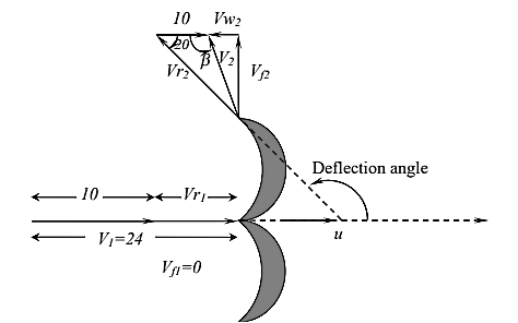
Velocity of jet, V₁ = Cv  =
=  = 23.7758 m/s
Vr1 = V1 –u =23.7758 - 10=13.7758 m/s
Assuming no shock and frictional losses we have Vr1 = Vr2 = 13.7758 m/s
Vw 2 = Vr2 Cos - u = 13.7758 x Cos (20) – 10 = 2.94 m/s
 ………………….Q=aV1

W=187.0106 KN-m/s2
Kinetic Energy = Input Power =

Hydraulic Efficiency nh 
Hydraulic Efficiency nh = 94.52%
Q8) A Kaplan turbine produces 60,000 kW under a head of 30m which has an overall efficiency of 92%. Taking the value of speed ratio = 1.6, flow ratio ⍦ = 0.5 and the hub diameter = 0.4 times the outer diameter. Find the diameter and the speed of the turbine.
A8)
P = 60000 kW
H = 30m,
n0= 0.92,
 = 1.6,
 = 0.5,
Db/ D0 = 0.4,


Q=221.60 m3/s


D0 =5.26m
UD = 
 =1.6
=1.6  =38.8177 m/s


N =140.9436 rpm
Q9) A jet of water of diameter 50 mm strikes a fixed plate in such a way that the angle between the plate and the jet is 25°. The force exerted in the direction of the jet is 1500 N. Determine the rate of flow of water.
A9)
Given:
Diameter of jet, d = 50 mm = 0.05 m
Area, a= (π/ 4) (0.05)²=.001963 m² 4
Angle,  = 40°
= 40°
Force in the direction of jet, Fn = 15000 N
Force in the direction of jet is given by as Fn =  av² sin²
As the force is given in Newton, the value of  should be taken equal to 1000 kg/m³
1500 =1000 x .001963 x V² x sin² 25°=.3506 V²
V² = 150 /0.025 = 6000
V = 77.45 m/s
Q Area x Velocity
= .001963 x 54.77= 0.1520 m³/s = 152.034 liters/s.
Q10) A jet of water of diameter 10 cm strikes a flat plate normally with a velocity of 20 m/s. The plate is moving with a velocity of 8 m/s in the direction of the jet and away from the jet. Find:
(i) the force exerted by the jet on the plate (ii) work done by the jet on the plate per second.
A10)
Given:
Diameter of the jet, d = 10 cm = 0.1 m
Area, a= (π/ 4) d² =(π/ 4) (0.1)² = .007854 m²
Velocity of jet, V = 20 m/s
Velocity of the plate, u = 8 m/s
(i) The force exerted by the jet on a moving flat vertical plate is given by equation
Fx =  a (V-u)² = 1000 x .007854 x (20-8)² N = 1130.976 N
(ii) Work done per second by the jet= Fx x u = 1130.976 x 8 = 9047.808 Nm/s.
Q11) Write a note on Factors affecting selection of Water Turbine.
A11) Some of the Factors affecting the Selection of Hydraulic Turbines
- Head
- Specific speed
- Rotational speed
- Efficiency of the turbine
Based on Head
Based on head requirement following Turbines are selected
Head | Head Range in meters | Suitable turbine |
Very low head | 3-10 | 1. Bulb turbine 2.Kaplan Turbine(less economical) |
Low head | 10-60 | 1.Kaplan Turbine 2.PropellorTurbine (up to 15m) |
Medium head | 60-150 | Francis Turbine |
High head | 150-350 | Pelton or Fransis |
Very high head | >350 | Pelton |
Based on Specific Speed
Specific speed plays an important role for selecting the type of the turbine. Also the performance of a turbine can be predicted by knowing the specific speed of the turbine. The type of turbine for different specific speed is given in Table below
Cavitation is most commonly seen in reaction turbines. So, while choosing a turbine, the cavitation factor for that particular turbine should be assessed to see if it is in a safe zone or not. The cavitation factor is determined by the turbine's specific speed. It is critical, particularly in the case of Kaplan, propeller, and bulb turbines.
Specific Speed RPM | Specific Speed | Suitable turbine |
10 -35 | 8.5-30 | Pelton single jet
|
35-60 | 30-51 | Pelton with two or more jet |
60-300 | 51-255 | Francis Turbine |
300-1000 | 255-860 | .Kaplan Turbine or PropellorTurbine |
Based on Rotational speed
The turbine's rotational speed is determined by the turbine's specific speed, frequency, and number of pairs of poles in the electric generator. As a result, the specified turbine's specific speed should provide the equivalent amount of generator rotation speed.
Based on Efficiency of turbine
Efficiency of turbines = Francis Turbine > Kaplan Turbine > Pelton Turbine
In general, the turbine's efficiency is highest when it is operating at a specified load. When a part-load or overload problem occurs, efficiency suffers, which is costly. Kaplan turbines are preferred in this circumstance.
Q12) The difference between radial and axial flow turbines are appended below.
A12)
Sr. | Radial Flow | Axial Flow |
1 | Radial entry of Water | Axial entry of water |
2 | 16-24 no. Of blades | 3 to 8 no. Of blade |
3 | Friction is high | Friction is low due to less no. Of vanes |
4 | Guide vanes Adjustable | Both guide and moving vanes adjustable |
5 | High efficiency only at high load | High efficiency even at part load |
6 | Size is large | Compact size |
7 | Specific ranges from 50-250 | Specific ranges from 250-850 |
Q13) Derive Expression for impact of jet on moving and fixed stationary plate.
A13) Force exerted by the jet on a stationary vertical plate
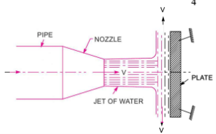
Consider a jet of water coming out from a jet of water from the nozzle collides with the vertical plate.
V = jet velocity, d = jet diameter, a = x – section area of the jet
The force that the jet exerts on the plate in the jet's direction.
Fx denotes the rate of change of momentum in the force's direction.
(Initial momentum – final momentum)/time = rate of change of momentum in the direction of force
After striking the plate, the jet will move along it. However, the plate is perpendicular to the jet. As a result, the jet will be deflected 90 degrees after impact. As a result, after striking, the component of the jet's velocity in the direction of the jet will be zero.
The force applied to the plate by the jet in the direction of the jet.
F= Rate of change of momentum in the direction of force
F= (Initial momentum - Final momentum)/Time
F= (Mass x Initial velocity - Mass x Final velocity)/Time
F= [Mass/ Time]x[Initial velocity - Final velocity]
F= (Mass/sec) x (velocity of jet before striking - velocity of jet after striking)
F=  aV [V - 0]
F=  aV²…………………………………………………..( mass/sec =
  x aV)
x aV)
We used initial velocity minus final velocity instead of final velocity minus initial velocity to derive the above equation.
When calculating the force put on the jet, the end velocity is subtracted from the initial velocity.
When calculating the force applied by the jet on the plate, however, initial velocity minus final velocity is used. When the density ( ) is expressed in SI units (kg/m3), the force (F) is expressed in Newtons (N). In S.I. Units, the value of p for water is 1000 kg/m3
Force on Flat Vertical Plate Moving in the Direction of Jet.
Fig. Shows a jet of water striking a flat vertical plate moving with a uniform velocity away from the jet.
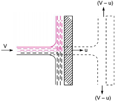
Let
V = Velocity of the jet (absolute),
a = Area of cross-section of the jet,
u= Velocity of the flat plate.
In this case, the jet does not strike the plate with a velocity V, but it strikes with a relative velocity, which is equal to the absolute velocity of jet of water minus the M velocity of the plate.
Hence relative velocity of the jet with respect to plate= (V-u)
Mass of water striking the plate per sec=  x Area of jet x Velocity with which jet strikes the plate
=  a x [V -u]
Force exerted by the jet on the moving plate in the direction of the jet.
Fx = Mass of water striking per sec x (Initial velocity with which water strikes - Final velocity]
=  a(Vu) [(V-a)-0] …………………….(Final velocity in the direction of jet is zero)
=  a(V-u)²
In this case, the work will be done by the jet on the plate, as plate is moving. For the stationary plates, the work done is zero.
Work done per second by the jet on the plate
= Force x (Distance in the direction of force/Time)
= Fx x u =  a(V-u)² x u
In equation if the value of p for water is taken in S.I. Units (i.e.. 1000 kg/m³), the work done will be in N m/s. Or watts
Q14) Describe use of guide vanes and Draft tube in context of Reaction Turbine.
A14) Guide Vanes: - A series of airfoil-shaped vanes, called the guide vanes or wicket gates, are arranged inside the casing to form some flow passages between the casing and the runner blades. The vanes are shaped according to the hydraulic design specification and given a smooth surface finish. The bearings of the guide vane shafts are lubricated with oil or grease.
Guide Vanes Function
The guide vanes direct the water onto the runner at an angle appropriate to the design. It provides the degree of adaptability to the quantity of water to be admitted to the runner in the wake of load variations.
Draft Tube: - The draft tube forms the water conduit from the runner to the draft outlet. It consists of the draft tube cone and the draft tube steel plate lining. It consists of the draft tube cone and the draft tube steel plate lining. The draft tube cone is a welded steel plate design and consists normally of two parts, the upper and lower cone. The inlet part of the upper cone is made of stainless steel. It is normally provided with two manholes for inspection of the runner from below. The lower part is designed as a dismantling piece and is mounted to a flange on the draft tube bend top. This design is always used for units where the runner is dismantled downwards. For units being dismantled upwards, the draft tube cone is made in one piece. The draft tube lining is completely embedded in concrete.
Draft Tube Function
The aim of the draft tube is also to convert the main part of the kinetic energy at the runner outlet to pressure energy at the draft tube outlet. This is achieved by increasing the cross-section area of the draft tube in the flow direction. In an intermediate part of the bend, however, the draft tube cross-sections are decreased instead of increased in the flow direction to prevent separation and loss of efficiency.
Q15) Describe ISO- Efficiency Curves for Turbines.
A15) Constant efficiency curves or Muschel curves or iso-efficiency curves
- These curves are obtained from speed versus efficiency and speed versus discharge curves for different gate opening.
- For a given efficiency from the
 curves, there are two speeds.
 - From
 curves, corresponding to two values of speeds there are two values of discharge.
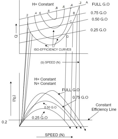
- Hence for a given efficiency there are two values of discharge for the particular gate opening.
- This means for a given efficiency there are two values of speeds and two values of discharge for a given gate opening.
- If the efficiency is maximum there is only one value.
- These two values of speed and two values of discharge corresponding to particular gate opening are plotted as shown in figure.
- The procedure is repeated for different gate opening and the curves Q vs N are plotted.
- The points having the same efficiency are called iso- efficiency curves.
- These curves are helpful for determining the zone of constant efficiency and for predicting the performance of the turbine at various efficiencies.
- For plotting the iso-efficiency curves horizontal lines representing the same efficiency are drawn on the
 speed curves.
 - The points at which these lines cut the efficiency curves at various gate openings are transferred to the corresponding Q~ speed curves.
- The points having the same efficiency are less then joined by a smooth curve.
- These smooth curves represent the ISO efficiency curve.