Unit – 5
Classifications of centrifugal pumps
Q1) Define slip, percentage slip and negative slip of a reciprocating pump.
A1)
Slip of pump is defined as the difference between the theoretical discharge (Qth) and actual discharge (Qact).
Slip = Qth Q act)
Percentage Slip =
=
=
=
Cd = Co-efficient of discharge
Negative Slip: In the majority of cases, the slip is positive. However, in some situations, the actual discharge of the pump may exceed the theoretical discharge, causing Cd to be greater than one and the slip to be negative, resulting in negative slip. This happens in pumps with a long suction pipe and a small delivery head, especially when they're running fast. This is because the inertia pressure opens before in the suction pipe builds up to the point where the delivery valve the suction stroke is finished. As a result, even before the delivery stroke begins, some liquid is pumped right into the delivery pipe. As a result, the real discharge will be higher than the theoretical discharge.
Q2) What do you mean by manometric efficiency, mechanical efficiency and overall efficiency of a centrifugal pump?
A2)
Various efficiencies related to centrifugal pumps are as follows:
- Mechanical efficiency, ηm
The ratio of power available at the impeller or power delivered by impeller to liquid to the power input at the shaft (motor power or shaft power) is known as mechanical efficiency.
∴ ηm = Power available at impeller, P(kW) / Shaft power, Ps (kW)
But, power available at impeller is given as, P = ρ (Q+q) Vw2 u2
ηm = {ρ (Q+q) Vw2 u2} / Ps = (Ps - Pmech losses) / Ps
Where, q = leakage loss
2. Manometric efficiency, ηmano
It is defined as the ratio of manometric head, Hm developed by the pump to the head imparted by the impeller to liquid. Mathematically,
∴ ηmano = Manometric head, Hm / Head imparted by impeller (Vw2 u2 / g)
∴ ηmano = (g Hm) / Vw2 u2
3. Overall efficiency, ηo
It is defined as the ratio of power output of the pump called water power to the shaft power.
Thus, ηo = Power output / Shaft Power, Ps
ηo = ρ g Q Hm / Ps
Q3) Define specific speed of a centrifugal pump. Derive an expression for the same
A3)
A centrifugal pump's specific speed is defined as the speed of a geometrically comparable pump that delivers one cubic metre of liquid per second against a one-metre head. Ns is the symbol for it.
Discharge Q is given by the relation
Q = Area x Velocity of flow
= π D x B x Vf or Q  D x B x Vf (i)
Where, D is Diameter of the impeller of the pump and B is width of the impeller.
We know that B  D
D
From equation (i), we have Q  D2 x V f ---------------------------- (ii)
We also know that tangential velocity is given by
u= (π D N)/60 or u  D N ---------------------------- (iii)
Now the tangential velocity (u) and velocity of flow (V) are related to the manometric head (H) as
u  V f
V f 
 ---------------------------- (iv)
Substituting the value of u in eqn (iii)
u  D N
D N

D 

Substituting the value of D in eqn (ii)
Q
 x V f
x V f
From (iv)
Q
 x
x 
Q

Q
 --------------------------- (v)
Where K is constant of proportionality, now according to definition when Q=1 m3/s, H=1 then N=Ns
1

K=
Substituting in (v)
Q

 =
= 
This is Specific Speed of Centrifugal pump
Q4) Discuss the effect of acceleration in suction and delivery pipes on indicator diagram.
A4)
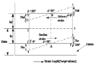
Theoretical Indicator diagram
It's a graph that shows the pressure head on the piston plotted along the vertical ordinate and the stroke length (swept volume is proportional to stroke length) displayed along the abscissa for one complete crank turn.
EF = atmospheric pressure head
AB = pressure head in the cylinder during suction, less than Hatm by hs
CD= pressure head in the cylinder during deliver, more than Hatm by hd
Work input to drive the pump = i 

Effect of Acceleration
Mass of the liquid influenced by acceleration =density multiplied by volume,
Force is mass X acceleration 
Pressure =Force/ area
 =
= 
Pressure head= Pressure/specific weight
On suction side

On Delivery side

During the suction stroke, the pressure head inside the cylinder will not be equal to hs, as it was in the ideal indicator diagram, but it will be equal to the sum of hs and has. Because has is positive at the start of the suction stroke, the total pressure head in the cylinder will be hs +has less than the atmospheric pressure head.
ϴ is 90 in the middle of the suction stroke, so has=0, and the pressure head in the cylinder will be hs lower than the atmospheric head. The pressure head in the cylinder will be hs - has below the atmospheric pressure head at the conclusion of the suction ϴ is 180 stroke and has is negative, so the pressure head in the cylinder will be hs - has below the atmospheric pressure head. For suction stroke; the indicator diagram will be show by 1A1, also the area of 1A1 = Area of 1'A1'
Similarly, the indicator diagram for the delivery stroke can be designed so that had is positive at the start of the delivery stroke and thus the pressure head in the cylinder is higher than the ambient pressure head. The pressure head in the cylinder will be hd + had
had = 0 in the middle of the delivery stroke, therefore the pressure head in the cylinder is equal to hd above ambient pressure head. Had is (-)ve at the end of the delivery stroke, therefore the pressure in the cylinder will be higher than the ambient pressure head. The pressure head in the cylinder will be hd - had
For delivery stroke; the indicator diagram will be show by 3B3, also the area of 3B3 = Area of 3'B3'
Q5) Discuss what air vessel is. Percentage of power saved if the pump is single acting Pump
A5)
An air vessel is a closed cast iron chamber with a bottom hole that connects to a suction or delivery pipe. Compressed air is contained in the vessel's upper part.
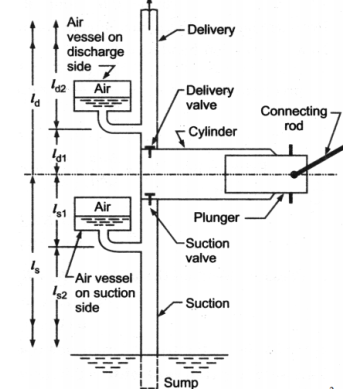
A reciprocating pump's air vessel functions similarly to an I.C. Engine's fly wheel. The compressed air at the top of the vessel can contract and expand to absorb the majority of the pressure variations. When the pressure rises, water over the mean discharge is driven into the air vessel, compressing the air inside. When the water pressure in the pipe drops, the compressed air ejects the excess water out, implying that the air vessel works as an intermediary reservoir on the suction side, accumulating water first before being delivered to the pump's cylinder. Water is sent to the air vessel first, then to the delivery pipe. The water in the pipe is constantly flowing.
Work Done by Air Vessel
In single Acting Cylinder mean Discharge from pump

Instantaneous Flow rate

Net discharge

If the equation is positive, liquid is flowing into the air vessel; if the equation is negative, liquid is flowing out of the air vessel; and if there is no liquid flowing into or out of the air vessel, the equation equals zero. The relation is parabolic
 =0
=0

This results in two valves of ϴ =18 degrees or 161 degrees
The discharge is equivalent to mean discharge for these crank angle positions.
The oscillations in the velocity of flow in suction and delivery pipes are reduced by using air vessels, which reduces head frictional losses in the pipes and saves a certain amount of energy. It is expected that the air vessel is installed relatively close to the pump cylinder, and that head loss due to friction in the tiny pipe between the pump and the air vessel is minimal. Because the flow velocity in the pipe beyond the air vessel is uniform and equal to the mean velocity, the power lost in friction per second is equal to
 =
= 
Power lost in friction per stroke when there is no air vessel

Power saved by fitting air vessel

The percentage of the power saved by air vessel installation
 %
%
Q6) Compare centrifugal and reciprocating pumps
A6)
Property | Centrifugal | Positive Displacement |
Effective viscosity range | Efficiency decreases with increasing viscosity (max. 200 centipoise) | Efficiency increases with increasing viscosity |
Pressure tolerance | Flow varies with changing pressure | Flow insensitive to changing pressure |
Efficiency decreases at both higher and lower pressures | Efficiency increases with increasing pressure | |
Priming | Required | Not required |
Flow (at constant pressure) | Constant | Pulsing |
Shearing (separation of emulsions, slurries, biological fluids, food stuffs) | High speed motor damages shear-sensitive mediums | Low internal velocity. Ideal for pumping shear sensitive fluids |
Q7) Classify Centrifugal Pumps
A7)
Classification of Centrifugal Pumps
- Based on Working Head:
- Low head pumps (up to 15m). Usually, they do not have guide vanes.
- Medium head pumps (15 to 40m). These usually are provided with guide vanes.
- High head pumps (above 40m). These are multistage pumps.
2. Based on type of Casing:
Casing is designed with the motive of decreasing the loss of kinetic head to minimum.
Based on various shapes of casings, centrifugal pumps can be classified as:
- Volute pump or constant velocity pump:
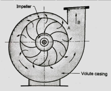
Figure shows a centrifugal pump with a volute or collecting passage round the impeller of gradually increasing area from cut water at A to delivery pipe at B. The cross-section is so designed to give a constant velocity in the volute of spiral shape. For this reason, it is also called as constant velocity volute. In such a volute casing the loss of energy is considerably reduce compared to a circular casing if employed. However, the conversion of kinetic energy into pressure energy is not possible. Due to this the efficiency of pump only increases slightly.
b. Vortex or variable velocity volute pump
An improvement of the design of volute pump shown in Figure. This pump has relatively larger overall diameter compared to pump shown in previous figure in order to provide an annular space between the impeller and volute passage.
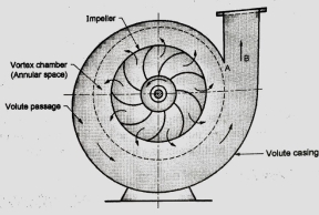
In this annular space called vortex chamber, there is a free vortex in which the velocity of flow of liquid falls as it passes into this chamber from impeller outlet to entry of volute passage. (Since in a free vortex, the velocity of whirl proportional to radial distance). Due to decrease in velocity the pressure increases radially from center outwards. The drawback of this arrangement is that to get an efficient chamber the dimensions become excessive and the pump becomes bulky and expensive. The volute pumps and vortex volute pumps are single stage pumps with horizontal shaft.
c. Diffuser or turbine pump
Figure below shows a diffuser or turbine pump which is similar to vortex volute pump, but a diffuser ring with guide vanes is fixed in annular space.
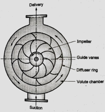
Function of guide vanes is to guide the liquid leaving the impeller in streamlined diverging passages into the volute chamber from where it flows to the delivery pipe. In case of multistage pumps, the liquid from volute chamber flows into the eye of impeller of the next stage pump and the final stage volute discharges into delivery pipe. This pump with diffuser ring becomes in fact a reversed reaction turbine and is commonly known as a turbine pump.
The guide vane passages so formed have an increasing cross-sectional area which reduces the velocity of flow; hence, the partial kinetic energy of the liquid is converted into pressure energy. Further conversion of kinetic energy into pressure energy takes place in the volute chamber of increasing cross-sectional area.
3. Based on liquid handling (Types of impellers)
Depending on the type and viscosity of liquid to be handled, a pump uses three types of impellers, accordingly the pumps are classified as follows:
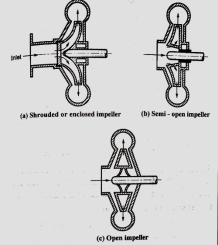
- Shrouded or enclosed impeller
In this type of impellers, the vanes of impeller are cast between two circular discs or plates (shroud) as shown in Figure. The plate on entry side is called crown plate and the plate on back or shaft side is called base plate. This arrangement provides better guidance for liquid to flow and prevents leaking of liquid from blade tips from one passage to another passage with high efficiency. These types of impeller pumps are mostly used for clear water or for other liquids of low viscosity free from dirt.
b. Semi-open impeller
These impellers have a plate only on back side called based plate as shown in Figure. Such an arrangement helps in dealing liquids mixed with fibrous materials. Therefore, these types of impellers can be used in sewage installation, sugar and pulp industry etc. with small amount of debris.
c. Open impellers
These types of impellers do not have any cover plate on either side of the vanes. Therefore, the vanes of an open impeller are open from both sides as shown in Figure. Open impellers are not so efficient but they we useful to deal with liquids which may contain suspended solids such as sand, grit, clay etc. since these pumps do not clog.
4. Based on relative direction of flow through Impeller
Based on relative direction of flow through Impeller, the pumps are classified as:
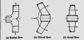
- Radial flow pumps
Most of the centrifugal pumps are radial flow type in which the liquid flows in the impeller in radial direction only as shown in Fig (a). In radial type of impellers, the liquid enters at the center of impeller axially and then it flows radially over impeller blades up to outer periphery. In this the pressure head is developed due to centrifugal force impressed upon the liquid.
b. Mixed flow pumps
Refer Fig (b). It is the modification of radial flow impeller in which the flow is the combination of axial and radial flow and the impeller resembles the propeller of a ship. These are also called as screw pumps due to their resemblance to shape of a screw.
The mixed flow impellers have large discharge rates of liquid compared to radial flow impellers at low heads. Therefore, these types of pumps are suitable for irrigation applications.
c. Axial flow pumps
In axial flow pumps the direction of flow of liquid through its impeller is in the axial direction only from inlet to exit as shown in Fig c. These pumps are designed for very large discharge rates at low heads; hence these are ideally suited for irrigation purposes. The pressure head developed in axial flow pump is not due to centrifugal action, rather it is due to flow of liquid on blades of aero foil section similar to generation of lift by the wings of an airplane. These pumps have adjustable blades similar to Runner blades of a Kaplan turbine.
5. Based on number of entrances to Impeller:
Centrifugal pumps based on number of entrances to the impeller can be classified as follows:
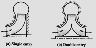
- Single entry pimp
In this pump the liquid enters only from one side into the impeller from suction pipe as shown in fig a. They are also called as single suction pump.
b. Double entry or double suction pump
Refer Fig b. In these pumps entry to impeller is from both sides of impeller. In such pumps the axial thrust is negligible. It is suitable for large discharge rates.
6. Based on number of impellers per shaft:
Based on number of impellers used per shaft, the pumps are classified as:
- Single stage pump:
It has one impeller and it is suitable for heads up to 40 m.
b. Multistage pump:
These pumps use two or more number of impellers in series depending upon the head requirements. In these pumps, the discharge of one pump from casing enters into the eye of impeller of the next pump in series. Total head developed by multistage pump is equal to algebraic sum of heads developed by each pump.
7. Based on shaft position:
Based on shaft position, the pumps are classified as:
- Horizontal shaft pump:
Usually, the centrifugal pumps are with horizontal shaft.
b. Vertical shaft pump:
These pumps are designed for specific applications and to save space. e.g., the deep well and marine pumps.
Q8) A horizontal pipe of diameter 450 mm is suddenly contracted to a diameter of 200 mm. The pressure intensities in the large and smaller pipe are given as 13.734N/cm2 and 11.774 N/cm2 respectively. Find the loss of head due to contraction if Cc=0.62. Also determine the rate of flow of water.
A8)
To find the head loss due to contraction,
Diameter of large pipe


Diameter of small pipe


Pressure in large pipe and small pipe


The head loss due to contraction,


By continuity equation,


Applying Bernoulli’s equation, (Z1=z2)

Also


Substituting values


Q9) A horizontal pipeline 40m long is connected to a water tank at one end and discharges freely into the atmosphere at the other end. For the first 25 m of its length from the tank, the pipe is 250 mm diameter and its diameter is suddenly enlarged to 400 mm. The height of the water level in the tank is 8 m above the centre of the pipe. Considering all losses of head which occurs, determine the rate of flow. Take f=0.01 for both sections of the pipes.
A9)
Given:
Total length of pipe, L=40m
Length of first pipe, L1=25m
Diameter of first pipe, d1=150mm=0.25m
Length of second pipe, L2=40−25=15m
Diameter of second pipe, d2=400mm=0.40m
Height of water, H=8m
Coefficient of friction, f=0.01
Applying Bernoulli's Theorem,


Where, loss at entrance

Head lost due to friction in pipe 1,

Loss due to sudden enlargement,

Head lost due to friction in pipe 2

But continuity equation,


Substituting the values of V1V1 in different losses, we get


Put the values in equation, we get


Therefore, the rate of flow,


Q10) The rate of flow of water through a horizontal pipe is 0.25m3/s. The diameter of the pipe which is 150 mm is suddenly enlarged to 200 mm. The pressure intensity in the smaller pipe is 11.772N/cm2. Find Loss of head due to sudden enlargement, Pressure intensity in large pipe, Power lost due to enlargement
A10)
Given:
Discharge, 
Diameter of smaller pipe


Diameter of larger pipe


Pressure in smaller pipe,


Loss of head due to sudden enlargement


Let pressure intensity in large pipe = P2

Since z1=z2

Putting values in equation (2), we get


Power lost due to sudden enlargement


Q11) Find the loss of head when a pipe of diameter 200 mm is suddenly enlarged to a diameter of 400 mm. The rate of flow of water through the pipe is 200 lit/s
A11)
Given:


Diameter of small pipe


Q12) Internal and external diameters of impeller of a centrifugal pump are 200 mm and 400 mm respectively. The pump us running at 900 rpm. The vane angles of impeller radially and velocity flow constant. Vane inlet and outlet angles are 20 and 30 degrees respectively
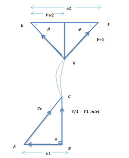
A12)
Given:
D1=200mm=0.2m=400mm=0.4m
N=1200rpm
Vane angle at inlet ϕ=20∘
Vane angle at outlet =ϕ=30∘
Radical on try i.e., α=90∘
Vw1=0
vf1=v1


vf1= vf2=3.430 m/s
Consider outlet velocity △EFG


Work-done by impeller/unit weight of water w

Q13) A centrifugal pump having outer diameter equal to two times the inner diameter and remaining at 1000 rpm works against a total head of 40m. The velocity of flow through the impeller is constant and equal to 2.5 m/s, The vanes are set back at an angle of 30 degree at outlet. If the outer diameter of the impeller is 500 mm and width at outlet is 50mm. Determine vane angle at inlet, work done (per second) manometric efficiency.
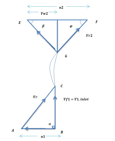
A13)
Given:
Speed N = 1000 rpm
Head, Hm = 40m
Velocity of flow,
vf1=vf2 = 2.5 m/s
Vane angle at ϕ = 400 outlet
Outer diameter of impeller, D2 = 500mm = 0.50m
Inner Diameter 
Width at outlet, B2 = 50mm= 0.05 m
Tangential velocity of impeller at inlet and outlet,


From Diagram Vane angle at inlet (θ)


From outlet velocity triangle


 =21.84 m/s
Work done is given by

Substituting all values

Manometric Efficiency is given by

 = 68.62 %
Q14) The diameter of an impeller of a centrifugal pump at outlet are 60 cm and at inlet 30cm respectively. The velocity of flow at outlet is 20 m/s and the vanes are set back at an angle of 40 degree at the outlet. Determine the minimum starting speed of the pump, if the manometric efficiency is 75%
A14)
Given:
Diameter at inlet, D1 = 30 cm = 0.30 m.
Diameter at outlet, D2 = 60 cm = 0.60 m.
Velocity of flow at outlet, vf2 = 2.0 m/s.
Vane angle at outlet, ϕ= 40 degree.
Manometric efficiency, nman = 70% = 0.70.
Let the minimum starting speed = N


Minimum Starting Speed of Centrifugal Pump

N = 63.66119[0.0314 N - 2.3835]
N = 1.99896N – 151.73
1. 9989N - N = 151.73

Q15) A single acting reciprocating pump, running at 50 rpm, delivers 0.0095 m3/s of water. The diameter of the piston is 200 mm and stroke length 400 mm. Find the theoretical discharge of the pump, Co-efficient of discharge, Slip and the percentage slip of the pump.
A15)
Given:
N=50rpm,
Qact=0.01m3/s
D=200mm=0.2mL=400mm=0.4m
Theoretical discharge:

Coefficient of discharge:


Q16) If separation occurs 2.8 m of water absolute. Determine: 1. The speed at which separation may takes place at the beginning of suction stroke. The speed of the pump if an air vessel is fitted on the suction side 2.8 m above the sump water level. Take atmosphere pressure head = 10.3 m of water and friction co-efficient, f = 0.01 Consider D=0.3m, L=0.5m, hs =3.2m, ds =0.2m, ls =9m, hsep =2.8m (absolute) Hatm =10.3m, f=0.01
A16)
Given:
D=0.3m, Area =0.0706
L =0.5m,
hs =3.2m,
ds =0.2m, area =0.0314
ls =9m,
hsep =2.8m (absolute)
Hatm =10.3m,
f=0.01


The speed at which separation may takes place at the beginning of suction stroke is 
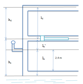


 ,
,


