Unit – 5
Pumps
Q1) Define slip, percentage slip and negative slip of a reciprocating pump.
A1) Slip of pump is defined as the difference between the theoretical discharge (Qth) and actual discharge (Qact).
Slip = Qth Q act)
Percentage Slip =
=
=
=
Cd = Co-efficient of discharge
Negative Slip: In the majority of cases, the slip is positive. However, in some situations, the actual discharge of the pump may exceed the theoretical discharge, causing Cd to be greater than one and the slip to be negative, resulting in negative slip. This happens in pumps with a long suction pipe and a small delivery head, especially when they're running fast. This is because the inertia pressure opens before in the suction pipe builds up to the point where the delivery valve the suction stroke is finished. As a result, even before the delivery stroke begins, some liquid is pumped right into the delivery pipe. As a result, the real discharge will be higher than the theoretical discharge.
Q2) What do you mean by manometric efficiency, mechanical efficiency and overall efficiency of a centrifugal pump?
A2) Various efficiencies related to centrifugal pumps are as follows:
- Mechanical efficiency, ηm
The ratio of power available at the impeller or power delivered by impeller to liquid to the power input at the shaft (motor power or shaft power) is known as mechanical efficiency.
∴ ηm = Power available at impeller, P(kW) / Shaft power, Ps (kW)
But, power available at impeller is given as, P = ρ (Q+q) Vw2 u2
ηm = {ρ (Q+q) Vw2 u2} / Ps = (Ps - Pmech losses) / Ps
Where, q = leakage loss
2. Manometric efficiency, ηmano
It is defined as the ratio of manometric head, Hm developed by the pump to the head imparted by the impeller to liquid. Mathematically,
∴ ηmano = Manometric head, Hm / Head imparted by impeller (Vw2 u2 / g)
∴ ηmano = (g Hm) / Vw2 u2
3. Overall efficiency, ηo
It is defined as the ratio of power output of the pump called water power to the shaft power.
Thus, ηo = Power output / Shaft Power, Ps
ηo = ρ g Q Hm / Ps
Q3) Define specific speed of a centrifugal pump. Derive an expression for the same.
A3) A centrifugal pump's specific speed is defined as the speed of a geometrically comparable pump that delivers one cubic metre of liquid per second against a one-metre head. Ns is the symbol for it.
Discharge Q is given by the relation
Q = Area x Velocity of flow
= π D x B x Vf or Q  D x B x Vf (i)
Where, D is Diameter of the impeller of the pump and B is width of the impeller.
We know that B  D
D
From equation (i), we have Q  D2 x V f ---------------------------- (ii)
We also know that tangential velocity is given by
u= (π D N)/60 or u  D N ---------------------------- (iii)
Now the tangential velocity (u) and velocity of flow (V) are related to the manometric head (H) as
u  V f
V f 
 ---------------------------- (iv)
Substituting the value of u in eqn (iii)
u  D N
D N

D 

Substituting the value of D in eqn (ii)
Q
 x V f
x V f
From (iv)
Q
 x
x 
Q

Q
 --------------------------- (v)
Where K is constant of proportionality, Now according to definition when Q=1 m3/s, H=1 then N=Ns
1

K=
Substituting in (v)
Q

 =
= 
This is Specific Speed of Centrifugal pump
Q4) Discuss the effect of acceleration in suction and delivery pipes on indicator diagram.
A4) Theoretical Indicator diagram
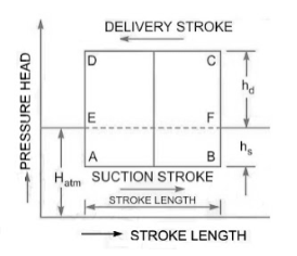
It's a graph that shows the pressure head on the piston plotted along the vertical ordinate and the stroke length (swept volume is proportional to stroke length) displayed along the abscissa for one complete crank turn.
EF = atmospheric pressure head
AB = pressure head in the cylinder during suction, less than Hatm by hs
CD= pressure head in the cylinder during deliver, more than Hatm by hd
Work input to drive the pump = i 
Effect of Acceleration
Mass of the liquid influenced by acceleration =density multiplied by volume,
Force is mass X acceleration 
Pressure =Force/ area
 =
= 
Pressure head= Pressure/specific weight
On suction side

On Delivery side

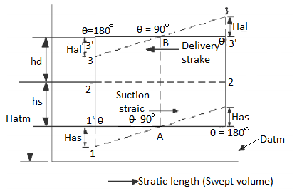
During the suction stroke, the pressure head inside the cylinder will not be equal to hs, as it was in the ideal indicator diagram, but it will be equal to the sum of hs and has. Because has is positive at the start of the suction stroke, the total pressure head in the cylinder will be hs +has less than the atmospheric pressure head.
ϴ is 90 in the middle of the suction stroke, so has=0, and the pressure head in the cylinder will be hs lower than the atmospheric head. The pressure head in the cylinder will be hs - has below the atmospheric pressure head at the conclusion of the suction ϴ is 180 stroke and has is negative, so the pressure head in the cylinder will be hs - has below the atmospheric pressure head. For suction stroke; the indicator diagram will be show by 1A1, also the area of 1A1 = Area of 1'A1'
Similarly, the indicator diagram for the delivery stroke can be designed so that had is positive at the start of the delivery stroke and thus the pressure head in the cylinder is higher than the ambient pressure head. The pressure head in the cylinder will be hd + had
had = 0 in the middle of the delivery stroke, therefore the pressure head in the cylinder is equal to hd above ambient pressure head. Had is (-)ve at the end of the delivery stroke, therefore the pressure in the cylinder will be higher than the ambient pressure head. The pressure head in the cylinder will be hd - had
For delivery stroke; the indicator diagram will be show by 3B3, also the area of 3B3 = Area of 3'B3'
Q5) Discuss what air vessel is. Percentage of power saved if the pump is single acting Pump.
A5) An air vessel is a closed cast iron chamber with a bottom hole that connects to a suction or delivery pipe. Compressed air is contained in the vessel's upper part.
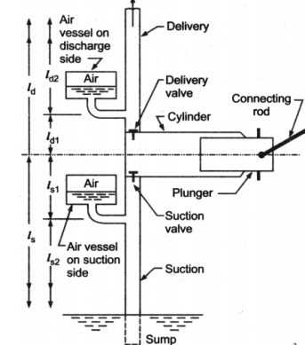
A reciprocating pump's air vessel functions similarly to an I.C. Engine's fly wheel. The compressed air at the top of the vessel can contract and expand to absorb the majority of the pressure variations. When the pressure rises, water over the mean discharge is driven into the air vessel, compressing the air inside. When the water pressure in the pipe drops, the compressed air ejects the excess water out, implying that the air vessel works as an intermediary reservoir on the suction side, accumulating water first before being delivered to the pump's cylinder. Water is sent to the air vessel first, then to the delivery pipe. The water in the pipe is constantly flowing.
Work Done by Air Vessel
In single Acting Cylinder mean Discharge from pump

Instantaneous Flow rate

Net discharge

If the equation is positive, liquid is flowing into the air vessel; if the equation is negative, liquid is flowing out of the air vessel; and if there is no liquid flowing into or out of the air vessel, the equation equals zero. The relation is parabollic
 =0
=0

This results in two valves of ϴ =18 degrees or 161 degrees
The discharge is equivalent to mean discharge for these crank angle positions.
The oscillations in the velocity of flow in suction and delivery pipes are reduced by using air vessels, which reduces head frictional losses in the pipes and saves a certain amount of energy. It is expected that the air vessel is installed relatively close to the pump cylinder, and that head loss due to friction in the tiny pipe between the pump and the air vessel is minimal. Because the flow velocity in the pipe beyond the air vessel is uniform and equal to the mean velocity, the power lost in friction per second is equal to
 =
= 
Power lost in friction per stroke when there is no air vessel

Power saved by fitting air vessel

The percentage of the power saved by air vessel installation
 %
%
Q6) Compare centrifugal and reciprocating pumps.
A6)
Property | Centrifugal | Positive Displacement |
Effective viscosity range | Efficiency decreases with increasing viscosity (max. 200 centipoise) | Efficiency increases with increasing viscosity |
Pressure tolerance | Flow varies with changing pressure | Flow insensitive to changing pressure |
Efficiency decreases at both higher and lower pressures | Efficiency increases with increasing pressure | |
Priming | Required | Not required |
Flow (at constant pressure) | Constant | Pulsing |
Shearing (separation of emulsions, slurries, biological fluids, food stuffs) | High speed motor damages shear-sensitive mediums | Low internal velocity. Ideal for pumping shear sensitive fluids |
Q7) Classify Centrifugal Pumps.
A7)
Classification of Centrifugal Pumps
- Based on Working Head:
- Low head pumps (up to 15m).
- Medium head pumps (15 to 40m).
- High head pumps (above 40m)
- Based on type of Casing:
- Volute pump or constant velocity pump:
- Vortex or variable velocity volute pump
- Diffuser or turbine pump
- Based on liquid handling (Types of impeller)
- Shrouded or enclosed impeller
- Semi-open impeller
- Open impellers
- Based on relative direction of flow through Impeller
- Radial flow pumps
- Mixed flow pumps
- Axial flow pumps
- Based on number of entrances to Impeller:
- Single entry pimp
- Double entry or double suction pump
- Based on number of impellers per shaft:
- Single stage pump
- Multistage pump
- Based on shaft position:
- Horizontal shaft pump
- Vertical shaft pump
Q8) Internal and external diameters of impeller of a centrifugal pump are 200 mm and 400 mm respectively. The pump is running at 900 rpm. The vane angles of impeller radially and velocity flow constant. Vane inlet and outlet angles are 20 and 30 degree respectively.
A8)
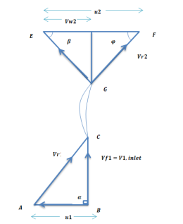
Given:
D1=200mm=0.2m=400mm=0.4m
N=1200rpm
Vane angle at inlet ϕ=20∘
Vane angle at outlet =ϕ=30∘
Radical on try i.e α=90∘
Vw1=0
vf1=v1


vf1= vf2=3.430 m/s
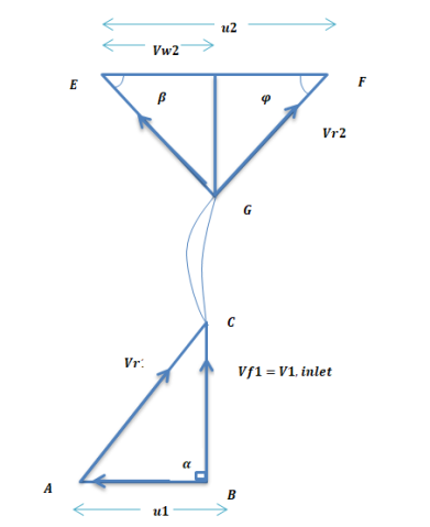
Consider outlet velocity △EFG


Work-done by impeller/unit weight of water w

Q9) A centrifugal pump having outer diameter equal to two times the inner diameter and remaining at 1000 rpm works against a total head of 40m. The velocity of flow through the impeller is constant and equal to 2.5 m/s, The vanes are set back at an angle of 30 degree at outlet. If the outer diameter of the impeller is 500 mm and width at outlet is 50mm. Determine vane angle at inlet, work done (per second) manometric efficiency.
A9)
Given:
Speed N = 1000 rpm
Head, Hm = 40m
Velocity of flow,
vf1=vf2 = 2.5 m/s
Vane angle at ϕ = 400 outlet
Outer diameter of impeller, D2 = 500mm = 0.50m
Inner Diameter 
Width at outlet, B2 = 50mm= 0.05 m
Tangential velocity of impeller at inlet and outlet,


From Diagram Vane angle at inlet ( θ )


From outlet velocity triangle


 =21.84 m/s
Work done is given by

Substituting all values

Manometric Efficiency is given by

 = 68.62 %
Q10) The diameter of an impeller of a centrifugal pump at outlet are 60 cm and at inlet 30cm respectively. The velocity of flow at outlet is 20 m/s and the vanes are set back at an angle of 40 degree at the outlet. Determine the minimum starting speed of the pump, if the manometric efficiency is 75%.
A10)
Given:
Diameter at inlet, D1 = 30 cm = 0.30 m.
Diameter at outlet, D2 = 60 cm = 0.60 m.
Velocity of flow at outlet, vf2 = 2.0 m/s.
Vane angle at outlet, ϕ= 40 degree.
Manometric efficiency, nman = 70% = 0.70.
Let the minimum starting speed = N


Minimum Starting Speed of Centrifugal Pump

N = 63.66119[0.0314 N - 2.3835]
N = 1.99896N – 151.73
1. 9989N - N = 151.73

Q11) A centrifugal pump with 1.2 m diameter runs at 200 r.p.m. And pumps 1880 litres/s, the average lift being 6 m. The angle which the vanes make at exit with the tangent to the impeller is 26° and the radial velocity of flow is 2.5 m/s. Determine the manometric efficiency and the least speed to start pumping against a head of 6 m, the inner diameter of the impeller being 0.6 m.
A11)
Given:
Dia. At outlet, D₂ = 1.2 m
Speed, N = 200 r.p.m.
Discharge, Q = 1880 litres/s = 1.88 m³/s
Manometric head, H₁ = 0.6 m
Angle of vane at outlet, = 26°
Velocity of flow at outlet, V₁ = 2.5 m/s
Dia. At inlet, D₁ = 0.6 m
(i) Manometric efficiency ( )
)


Minimum Starting Speed of Centrifugal Pump

Q12) A single-stage centrifugal pump with impeller diameter of 30 cm rotates at 2000 r.p.m. And lifts 3 m of water per second to a height of 30 m with an efficiency of 75%. Find the number of stages and diameter of each impeller of a similar multistage pump to lift 5 m of water per second to a height of 200 metres when rotating at 1500 rpm.
A12)
Given:
Single-stage pump:
Diameter of impeller, D₁ = 30 cm = 0.30 m
Speed, N₁ = 2000 rpm.
Discharge, Q₁ = 3 m³/s,
Height, Hm1 = 30 m
Efficiency  = 75% = 0.75.
Multistage similar pump:
Discharge, Q₂ = 5 m³/s
Total height =200m
Let the height per stage be Hm2
Speed, N₂ = 1500 .pm.
Diameter of each impeller D2
Specific Speed of Pump


Number of Stages =Total Head/Head per stage= 200/28.71 =6.96 
Also,


Q13) A one-third scale model of a pump was tested in a laboratory at 1000 r.p.m. The head developed and the power input at the best efficiency point were found to be 8 m and 30 kW respectively. If the prototype pump has to work against a head of 25 m, determine its working speed, the power required to drive it and the ratio of the flow rates handled by the two pumps.
A13)
Given
Speed, Nm = 1000 rpm.
Height, Hm1 = 8 m
Power of model Pm =30Kw
Let Np, Dp, Qp HmP be prototype counterparts
Also, Diameter are one-third

Speed of prototype


Power develop by prototype


Ratio of Flow rates


Q14) A single acting reciprocating pump, running at 50 rpm, delivers 0.0095 m3/s of water. The diameter of the piston is 200 mm and stroke length 400 mm. Find the theoretical discharge of the pump, Co-efficient of discharge, Slip and the percentage slip of the pump.
A14)
Given:
N=50rpm,
Qact=0.01m3/s
D=200mm=0.2mL=400mm=0.4m
Theoretical discharge:

Coefficient of discharge:


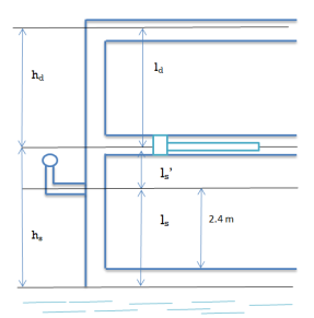
Q15) If separation occurs 2.8 m of water absolute. Determine: 1. The speed at which separation may takes place at the beginning of suction stroke. The speed of the pump if an air vessel is fitted on the suction side 2.8 m above the sump water level. Take atmosphere pressure head = 10.3 m of water and friction co-efficient, f = 0.01 Consider D=0.3m, L=0.5m, hs =3.2m, ds =0.2m, ls =9m, hsep =2.8m (absolute) Hatm =10.3m, f=0.01.
A15)
Given:
D=0.3m, Area =0.0706
L =0.5m,
hs =3.2m,
ds =0.2m, area =0.0314
ls =9m,
hsep =2.8m (absolute)
Hatm =10.3m,
f=0.01


The speed at which separation may takes place at the beginning of suction stroke is 


 ,
,


