Unit - 2
Static failure theories
Q1) Explain Maximum Normal Stress Theory (Rankine Theory) with proper Region of safety
A1) Maximum Normal Stress Theory
This theory was proposed and credited to W.J.M Rankine in 1850.Maximum Normal Stress Theory predicts failure of machine component which are subject to complex loading. The theory states “Failure of Mechanical component subject to biaxial or tri-axial stress occurs when maximum principal stress reaches the yield or ultimate strength of material”.
Explanation
Considering the principals stresses be σ1 > σ2> σ3
So, the maximum principal stress is σ1
So, failure will occur at σ1 = Syt or Sut
Considering Factor of safety
σ = Syt / FOS or σ = Sut / FOS
σ = Syc /FOS σ = Suc / FOS
This theory is not a safe measure for ductile materials and is not recommended, but it gives good prediction with brittle materials.
Construction of Region of safety
For biaxial stresses there will be two principal stresses σ1 and σ2 let them be plotted on X and Y axes
Tensile stresses are positive and compressive stresses are negative and are equal in magnitude that is Syt= Syc
The equation of line passing through a point on axis is axis = distance of point from origin
According to theory, only maximum principal stress is considered, other are neglected
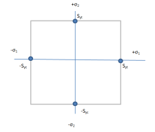
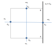
Case 1: σ1 > σ2, Let σ1 be tensile stress and σ2 be compressive stress.
Neglecting smaller stress σ2 and considering limiting factor of σ1 that is Syt.
Therefore, boundary will be σ1=+Syt. Draw line AB
Case 2: σ1 > σ2, Let σ1 be compressive stress and σ2 be tensile stress.
Neglecting σ2 and considering limiting factor of σ1 that is -Syc. Therefore, boundary will be σ1=-Syc. Draw line DC
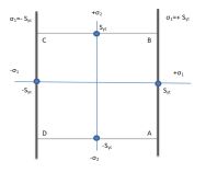
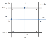
Case 3: σ2 > σ1, Let σ2 be tensile stress and σ1 be compressive stress.
Neglecting σ1 and considering limiting factor of σ2 that is Syt. Therefore, boundary will be σ2=+Syt. Draw line CB
Case 4: σ2 > σ1, Let σ2 be compressive stress and σ1 be tensile stress.
Neglecting σ1 and considering limiting factor of σ2 that is -Syc. Therefore, boundary will be σ2=-Syc. Draw line DA
According to theory if coordinates of σ1 and σ2 falls out of square ABCD formed by lines, then component will fail
Q2) Explain Maximum Shear Stress Theory with proper Region of safety
A2) This theory is credited to CA Coulomb, H Tresca and JJ Guest. The theory States that “Failure of mechanical component subjected to bi-axial or tri-axial stress occurs when the maximum shear stress at any point of component becomes equal to maximum shear stress in standard specimen of tension test, when yielding starts”. The Maximum Shear Stress theory predicts that yield strength in shear is half of yield strength in tension
Sys = 0.5 * Syt
Explanation
Considering the principals stresses be σ1, σ2 and σ3 at point on component the shear stress on plane would be
 ,
, ,
, .
.
According the theory largest stress  is equal to Syt/2,
 or σ1 – σ2 =
Similarly for all planes σ2 – σ3 = , σ3 – σ1 =
 ,
,
For compressive stress
σ1 – σ2 = ,
,
σ2 – σ3 = ,
,
σ3 – σ1 =
Assuming  =
= ,
,
The equation can be written as
σ1 – σ2 =
σ2 – σ3 =
σ3 – σ1 =
Construction of Region of safety
The equation x + y=1 is equation of line with slope 45 degrees, σ1 – σ2 = is line with slope of 45 degrees and points on =
 in respective quadrant
In first quadrant both stress are positive so limiting condition depends on magnitude, if σ1 > σ2 then σ1=+Syt. Draw line AB, if σ2 > σ1 then σ2=+Syt. Draw line CB
In third quadrant both stress are negative so limiting condition depends on magnitude, if σ1 > σ2 then σ1=-Syt. Draw line DE, if σ2 > σ1 then σ2=-Syt. Draw line EF
In second quadrant both stress are opposite so limiting condition depends on their difference,
σ1 -σ2 =-Syt. Draw line DC,
In fourth quadrant both stress are opposite so limiting condition depends on their difference,
σ1 -σ2 =+Syt. Draw line FA
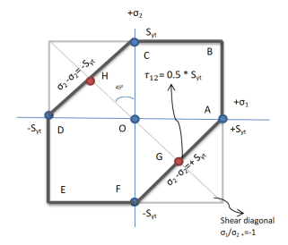
The complete region is hexagon ABCDEFA and if coordinates lie in this region the component is safe. To find the dimension of component factor of safety is considered
Considering FOS to find dimension of component,
 ,
,  ,
,
Q3) What are types of failures? Name the failure theories and Define shear diagonal
A3) if element cease to function then it is failed. There are two types of failure
- Yielding- This is due to excessive inelastic deformation rendering the machine part unsuitable to perform its function. This mostly occurs in ductile materials.
- Fracture- in this case the component tears apart in two or more parts. This mostly occurs in brittle materials.
- Maximum Principal/Normal Stress Theory (Rankine’s Theory)
- Maximum Shear Stress Theory (Guest’s Theory)
- Maximum Principal /Normal Strain Theory (Saint’s Theory)
- Maximum Strain Energy Theory (Haigh’s Theory)
- Maximum Distortion Energy Theory (Hencky & Von Mises Theory)
Shear diagonal: Shear diagonal or line of pure shear is the locus of all points, corresponding to pure shear stress
Q4) Differentiate between ductile and brittle fracture. Explain the significance of ductile Brittle transition temperature.
A4)
Parameter | Brittle | Ductile |
Plastic Deformation | Large | Small |
Necking | NO | Yes |
Crystal Packing structure | BCC, HCP | FCC |
Fracture surface | Rough contours, dirty surface | Sharp facets which reflect light |
Materials | Ceramic, Glass | Most Metals |
Warning sign | NO | Yes, Plastic deformation |
Crack propagation | Fast | Slow |
Deformation | Little | Extensive |
Strain Energy Required | Lower | Higher |
Stress during cracking | Constant | Increasing |
Stress v/s Strain | 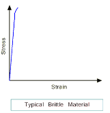 | 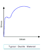 |
Shape diagram  |
 |

|
Some metals which are ductile at room temperature can become brittle at low temperatures; this temperature is called ductile to brittle transition temperature
The ductile to brittle transition temperature is strongly dependent on the composition of the metal. Steel is the most commonly used metal that shows this behavior.
For some steels the transition temperature can be around 0°C, and in winter the temperature in some parts of the world can be below this. As a result, some steel structures are very likely to fail in winter.
So, it is significant to design the component considering the ductile Brittle transition temperature if the component is subject to low temperatures, the composition of material must be altered to lower this transition temperature of material to prevent brittle failures at low temperatures
Q5) Differentiate between NDT and destructive testing.
A5)
Parameters | Destructive | Non-Destructive testing |
Measurements | Quantitative, direct and reliable | Mostly Qualitative, quantitative are also possible, Indirect, Reliability is not verified |
Test | Test are not made on component directly, but a prototype | Test are made on actual object |
Properties Measurement per Test per object | One to two, as object is destroyed further testing not possible | Many tests can be performed on single object to get many property measurements |
In-service Testing | Not possible | Possible |
Preparation cost | High | Low |
Time required for test | High | Mostly low |
Q6) What is factor of safety and what is its importance? Also explain the Tresca and Von-mises failure theory.
A6) Factor of safety: It is defined as ratio of maximum stress to working stress
Mathematically FOS = 
For Ductile material, FOS = 
For brittle material, FOS = 
Typical values
Application | FOS |
Aircraft components | 1.5-2.5 |
Bolts | 8.5 |
Pressure vessels | 3.5-6 |
Reliable material, normal condition | 1.3-1.5 |
Ordinary material, normal condition | 2-2.5 |
Unreliable material, severe condition | 3-4 |
Importance of FOS
There is variation in properties of material like yield strength, ultimate strength
Uncertainty in variation of external loads and forces
Variation in dimension of component due to lack of workmanship
To ensure safety of component from above mentioned variation and uncertainty, Factor of Safety is useful in Design
Tresca Theory
This theory is credited to CA Coulomb, H Tresca and JJ Guest. The theory States that “Failure of mechanical component subjected to bi-axial or tri-axial stress occurs when the maximum shear stress at any point of component becomes equal to maximum shear stress in standard specimen of tension test, when yielding starts”. The Maximum Shear Stress theory predicts that yield strength in shear is half of yield strength in tension
Sys = 0.5 * Syt
Explanation
Considering the principals stresses be σ1, σ2 and σ3 at point on component the shear stress on plane would be
 ,
, ,
, .
.
According the theory largest stress  is equal to Syt/2,
 or σ1 – σ2 =
Similarly for all planes σ2 – σ3 = , σ3 – σ1 =
 ,
,
For compressive stress
σ1 – σ2 = ,
,
σ2 – σ3 = ,
,
σ3 – σ1 =
Assuming  =
= ,
,
The equation can be written as
σ1 – σ2 =
σ2 – σ3 =
σ3 – σ1 =
Von-Mises Theory
This is also known as Distortion-Energy Theory. The theory states that failure of mechanical component subject to bi-axial or tri-axial stress occurs when strain energy of distortion per unit volume at in any point in component becomes equal to strain energy of distortion per unit volume in standard specimen of tension test when yielding starts
The unit cube is subjected to threes principal stresses σ1, σ2 and σ3, the strain energy will be
 ----------------1
ε1, ε2 and ε3 are strains
Also,
 -------------------------2
Therefore,
From I and 2
 ----------3
Total strain energy is resolved in two components Uv correspond to change in volume and no distortion change, Ud correspond to change in distortion and no change n volume
U= Ud+ UV
 ---------4
Ud = U - UV
From 3 and 4
 ------------------------------------------------5
For simple tension test σ1= Syt and σ2=σ3=0
 ------------------------------------------------6
Therefor from 5 and 6 criterion for failure for distortion theory is expressed as

For bi-axial load σ3=0 and 

Replacing  by
by 

Therefore, according to distortion-energy theory, yield strength in shear is 0.577 times the yield strength in tension
Q7) Explain the Griffith criteria of brittle fracture.
A7) Griffith equation defines relation between applied normal stress and crack length. Griffith established the criterion that a crack will propagate when decrease in elastic strain energy is at-least equal to energy required to create a new crack surface.
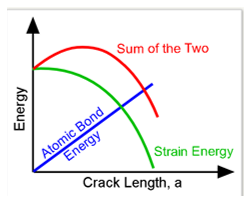
A loaded brittle body undergoing a crack expansion, the atomic or surface energy (S) is absorbed in crack growth while some stored Strain energy (U) is released as crack expands. The atomic energy (S) has constant value per unit area and this is linear to crack length (a). Strain energy is related to square of crack length and hence has parabolic relation
Q8) Write short note on Mohr coulomb failure criterion
A8)
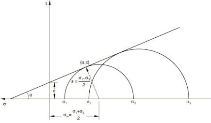
The Mohr coulomb criterion describes a linear relationship between normal and shear stresses at failure. It represents the linear envelope that is obtained from a plot of the shear strength of the material versus applied normal stress
Equation: τ=c−σtanϕ, τ = c – σ
C = Shear stress intercept
𝜎 = Normal stress
∅ = Angle of internal friction
The angle of friction (Ø) depends upon the grain size. If Ø = 0, Mohr coulomb criterion is reduced to the Tresca criterion. If Ø = 90, then Mohr coulomb model is equivalent to the Rankine model and higher values of Ø are not allowed
5Mohr circle is plotted between principle stresses and residual stress. Instrument is used to obtained values of 𝜎1 and 𝜎3. Peak shear strength is indicated by Shear intercept line
Strength of rock material is described by radius of circle, smaller the circle lowers the strength, larger the circle higher the strength of rock if circle is inside the line. Circles are combination of maximum load and confined pressure. The tangent point between circle and shear intercepts is maximum strength of rock and rock will fail at this point, the state of stress is called critical stress, so for safe design the circle must not touch the line that state is called safe state of stress
Cracks are produced with releasing residual stress when load increased to maximum point, lower the cracks in rock higher the residual stresses. Fine grain gives high strength than coarse grain
Q9) What is Fatigue limit? Draw S-N curve and explain its importance.
A9) Fatigue limit
Fatigue limit is also called endurance limit (Se), It is limit below which infinite number of repetitive load cycles of completely reversed bending stress can be applied before causing any fatigue failure on new standard specimen.
The fatigue limit term is used for materials having distinct limit like ferrous alloys whereas fatigue strength term is used when material don’t have distinct limit and can even fail at small stress amplitude
SN curve
Fatigue properties of material are described by SN curve. It is also called has Wohler curve
SN curve is curve describe relation between cycle stress amplitude and number of cycles the specimen holds till failure
Horizontal axis represents “No of cycle” in logarithmic scale; Vertical axis can either be in linear or logarithmic scale and can either represent “stress amplitude” or maximum stress
SN curve are found out by fatigue testing carried out on metal coupon testing machine, in which small metal coupon is placed and cyclic stress with constant amplitude is applied till specimen fails or exceed large No of cycles (N>10e6) and results are interpreted infinite life.
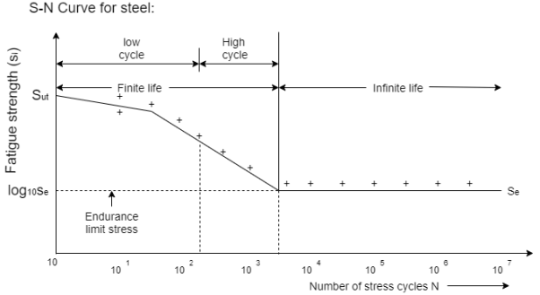
Regions of SN curve
Infinite region
In this region, the stress levels are below a certain number and infinite no if cycles can be performed without causing fatigue failure. To determine if a component is operating in the infinite life region, the Goodman-Haigh diagram is often used. See in figure steel has distinct limit whereas metals like aluminum and other do not always have distinct limit.
Elastic region
In this region, stress and strain exhibit linear relationship. After each load cycle, material returns to original shape. This region is also called High cycle fatigue region, because high number of stress cycles at low amplitude can cause material to fail. Residual stresses and sharp counters in geometry can affect the failure of material, smooth geometry decreases crack initiation
Plastic Region
In this region material experience high stress and causes permanent change to shape of material. This region is also called as the “Low Cycle Fatigue” region as a low number of stress cycles, with a high amplitude result in failure.
SN curve Slope (K factor)
The slope of the log-log SN-Curve is defined as “k-factor”. This “k-factor” governs the relationship between the stress level and the number of cycles to failure.
Wohler has developed the k-factor to easily relate the load, stress to the life, number of cycles to failure.
As this is log v/s log relationship, a small change in stress amplitude can cause very large change in the fatigue life
This helps in increasing the speed of testing
Q10) What is non-destructive testing (NDT)? Explain in detail any two NDT methods for Surface crack detection.
A10) According to this method ferromagnetic materials Different test methods are used depending on the application. Essential influencing factors are the test material, the size, the defect pattern, and the test task, as well as the required cycle time and the available budget.
Visual Inspection (VT)
During visual inspection procedures, surface-related quality features such as shape deviations, defects, or the surface condition of a component are viewed and evaluated with the naked eye or using optical gadgets like magnifying glasses, microscopes, or endoscopes. Prior to all other destructive and non-destructive testing methods, visual inspection is initially carried out in a comprehensive test and is used for various product shapes according to specified test instructions.
Dye penetrant testing
• A liquid with high surface wetting characteristics is applied to the surface of the part and allowed Time to seep into surface breaking defects.
• The excess liquid is removed from the surface of the part.
• A developer (powder) is applied to pull the Trapped penetrant out the defect and spread it on the surface where it can be seen.
• Visual inspection is the final step in the Process. The penetrant used is often loaded with a fluorescent dye and the inspection is done under UV light to increase test Sensitivity.
Q11) Name some of the methods used for non-Destructive testing
A11)
Visual inspection
Die penetration
Eddy current testing (ET)
Magnetic particle testing (MT)
Ultrasonic testing (UT)
Q12) Explain Magnetic particle testing
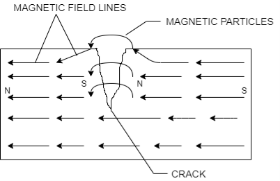
A12) This is non-Destructive Testing used to detect the crack. The basic principle is that if the crack is present on magnetized ferrous component surface the north and south poles are formed on crack. The magnetic field lines exit the North Pole and enters South Pole, but if crack is present the magnetic field lines are spread out as air cannot permit as high magnetic fields lines per volume as magnet can. This spread out is called flux leakage.
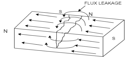
When the iron particle or other ferrous particles are sprinkled the particles not only are attracted to poles of magnet, but also around the crack, these particles are more visible than actual cracks and hence the cracks are located
Process
- Surface preparation- removes dust, rust, paint to ensure adequate contact area
- Pre-Demagnetization to remove the residual magnetism to avoid false detection
- Magnetize the component using either direct or indirect magnetization techniques
- Apply magnetic particle which have high permeability to increase sensitivity to small leakage and low retentively to avoid attracting to each other.
- On basis of carrying agent the application of magnetic particle can be wet or dry, wet method can detect small cracks due to increased mobility of particle in suspension around component tested and particle size is also 10um. As the particle surrounds the component dust accumulation is eliminated. Dry method uses two size a smooth 50um and coarse 150um. Dry method is useful for detection of crack on smooth surface and shallow surface cracks
- Viewing the cracks by using either red paste with daylight or florescent paste with black light. Marking the crack identification after draining all magnetic particle ink.
Demagnetized the component either by heating above Curie temperature or applying reverse and decreasing magnetic field
Q13) Explain Ultrasonic Testing
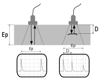
A13) Ultrasonic Testing (UT) uses high frequency sound waves typically in the range between 0.5 and 15 MHz to conduct examinations and make measurements.
Typical pulse-echo UT inspection system consists of the transmitter/receiver, transducer, and a display device. A pulser unit generates the ultrasonic wave which is passed through the object and if there is crack some waves are reflected back, by knowing the travel time, distance from defect can be calculated Ultrasonic testing is used in a wide range of industries as this can be used to inspect many materials UT is ideally used for inspection of dense, crystalline structures such as metals. Ceramics, plastics, composites and concrete can also be successfully inspected See in figure on right side D is distance from defect and peak at D is Crack Echo, also on left side the transmitted Echo is almost equal to received echo, but at right side reflected echo is less because some waves are reflected early at crack echo
Advantages
Can detect both surface and sub-surface defects
High penetration depth than other NDT
Only one side of object as to be free to inspect in pulse echo UT
High accuracy in determining Distance and Shape
Less preparation and instant results
It is nonhazardous to operators or nearby personnel and has no effect on material
It has other uses, such as thickness measurement, in addition to flaw detection.
Its equipment can be highly portable or highly automated. Detailed images can be produced with automated systems.
Disadvantages
Surface must be accessible to transmit ultrasound.
Skill and training are more extensive than with some other methods.
It normally requires a coupling medium to promote the transfer of sound energy
into the test specimen.
Materials that are rough, irregular in shape, very small, exceptionally thin or not
homogeneous are difficult to inspect.
Cast iron and other coarse-grained materials are difficult to inspect due to low
sound transmission and high signal noise.
Linear defects oriented parallel to the sound beam may go undetected.
Reference standards are required for both equipment calibration and the
characterization of flaws.
Q14) Explain Eddy current testing
A14) Eddy current technique is for the detection of surface can also be used to detect subsurface flaws, conductivity measurement and coating thickness measurement.
Eddy currents are produced in any electrically conducting material that is subjected to an alternating magnetic field ranging from 10Hz to 10MHz. To generate the alternating Magnetic field alternating current is passed through a coil. The coil can be arranged in many shapes and can have about 500 turns of wire. The magnitude of the eddy currents generated in the product is function of conductivity, permeability and geometry.
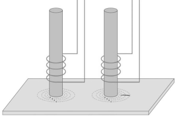
To detect changes in material or geometry, a coil is exited and its impedance is measured, change in impedance implies change in material or geometry The most simple coil comprises a ferrite rod with several turns of wire wound at one end and other end is positioned close to the surface of the product to be tested. If there is a crack in the product surface the eddy currents must travel farther around the crack and this is detected by the impedance change. These coils are connected to CRT display to see changes
See in figure left side has no crack and thus there is no distortion. On right side circles are distorted, current flow in and out of crack increasing impedance
Coils can be used in pair with single winding, double winding, and transformer type with 3 windings. Single winding is used for complex shapes, Differential winding are used for higher speed and transformer type are used in testing tubes and pipes
The technique is sensitive to the material conductivity, permeability, roughness, texture; dimensions of product thus can affect the detection. This can be improved by using multiple test frequency and shapes of coil. High test frequency causes low penetration while low frequency has less sensitivity
Advantages
- Can be used for detection of a wide range of conditions of conducting material, such as defect detection, composition, hardness, conductivity in a wide variety of engineering metals.
- Information can be provided in simple terms and for higher information phase display can be used
- Compact and portable units are available.
- No consumables
- Flexibility in selection of probes and test frequencies, to suit different applications.
- Can be automated totally
Q15) Write short note on Radiography.
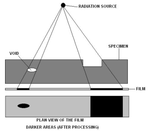
A15) This technique is suitable for the detection of internal defects in ferrous and non-ferrous metals and other materials. X-ray or Gamma rays are used. The penetrating radiation is absorbed by the material through which it passes and absorption increases with increase in thickness of material
The principal is same for both X-rays and Gamma rays. They have the property of converting silver halide crystal present in photographic film to metal silver proportional to intensity of radiation reaching to form the latent image which can be developed as photographic field
In X-radiography, X-rays are generated electrically and the penetrating power is determined by the number of volts applied to the X-Ray tube. The Intensity, the exposure time measured in milliamperes minutes is governed by the amperage of the cathode in the tube.
In Gamma radiography the isotope like iridium governs the penetrating power and cannot be change for isotope. Intensity of the radiation is set at the time of supply of the isotope. The intensity of radiation from isotopes is measured in Becquerel’s which reduces over a period of time with respect to the half-life. For example, the half-life of Iridium 192 is 74 days the exposure factor is a product of the number of curies and time, usually expressed in curie hours.
The exposure time must be increased as intensity decreases and isotopes must be disposed properly once it’s uneconomical. Also, the isotopes must be kept in proper shielding to avoid contamination of environment and prevent harms to operator.
Process
- The film with intensifying screen is placed close to the surface of the subject. Intensifying screen is use decrease the exposure time of test
- The radiation source is placed at other end and subject is placed between source and film, son the radiation passes through subject to film
- Once the exposure time is over, film is dried developed and viewed. Accessories like radiation monitor, image quality checker and dark room equipment along with consumables like film developer chemicals are needed to develop film
Advantages of Radiography
• Pictorial information which can be stored and view later and distant from the test.
• Can be used on any material with thin section
• Sensitivity declared on each film.
Disadvantages of Radiography
• Health Hazard and storage problem
• Can’t deal properly with thick section and beam must be directed accurately for two-dimensional defects.
•Other accessories, Film processing and viewing facilities, consumables are necessary
• Can’t detect surface defect and do not provide depth information of defect, only planer information is provided