Unit – 5
Refrigeration Cycles
Q1) A reversed Carnot cycle refrigerator extracts 500 kJ/min heat from a refrigerated space maintained at –16oC and rejects heat to the atmosphere at 27oC. Calculate the amount of work required to run the refrigerator.
A)
For refrigerator working on reversed Carnot cycle.


Also it is given that 

Work input required, 
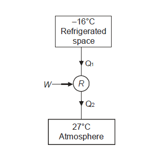
Q2) A refrigerator with a capacity of 800 tonnes can operate between –5°C and 27°C. Determine the mass rate of ice formation using water supplied at a temperature of 27oC in the atmosphere. Find out what the minimum hp requirement is. Consider a refrigerator that operates on a reversed Carnot cycle. The latent heat of ice formation from water is 335 kJ/kg.
A2)
Refrigeration capacity=800×3.5=2800 kJ/s=Heat extraction rate
Let the ice formation rate be ‘m’ kg/s
Heat to be removed from per kg of water for its transformation into ice.
=4.18×(27-0)+335 kJ/kg
=447.86 kJ/kg
Ice formation rate=
Mass rate of ice formation=6.25 kg/s
COP of refrigerator=
Here 


HP required=448.34 hp
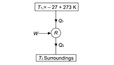
Q3) It takes 3 hp per tonne of refrigeration to maintain a temperature of –27oC in a refrigerator running on the Carnot cycle. Determine the COP of the cycle and the temperature of the environment to which the heat is rejected by the refrigerator.
A3)
Given:


COP=1.56
Equating COP, 

Temperature of surroundings=403.69 K
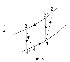
Q4) In an air refrigeration cycle, the pressure ratio is 8, the temperature of the air at the start of compression is –30oC, and the air is cooled to 27oC after compression. The isentropic efficiency of compression and expansion processes is 85 and 90 percent, respectively. Determine the refrigeration capacity and the performance coefficient. Consider the following conditions: Cp = 1.005 kJ/kg K, γ = 1.4, and an air flow rate of 1 kg/s.
A4)
Given:

During process 1-2’,


Theoretical temperature after compression 
For compression process,


For expansion 3-4’, 


Work during compression, 

Work during expansion 

Refrigeration effect is realized during process, 4-1. So refrigeration effect shall be


Net work required=
Refrigeration capacity=1.75 ton or 61.25 kJ/s
COP=0.56
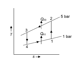
Q5) In a refrigeration system, air exits the refrigerated space at 7oC and 1 bar and is compressed isentropically to 5 bar. After being compressed, the air is cooled to 27oC at this pressure before being expanded isentropically to 1 bar and discharged into refrigerated space. Calculate the system's COP.
A5)
Given: 


For isentropic compression process


For isentropic expansion process:


Heat rejected during process 2-3, 


Refrigeration process heat picked during process 4-1, 


Net work=

W=53.16 m kJ


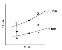
Q6) In a refrigerator that operates on the Bell Coleman cycle, air enters the compressor at 1 bar and –10oC and is compressed to 5.5 bar. Compressed air is cooled to 27oC at the same pressure before being routed to an expander for expansion up to 1 bar before passing through refrigerated space. Determine the refrigeration capacity, horsepower required to run the compressor, and system COP if the air flow rate is 0.8 kg/s.
A6)
T1 = –10ºC or 263 K, P1 = 1 bar, T3 = 27ºC or 300 K, P2 = 5.5 bar, m = 0.8 kg/s.
For process 1-2,


For process 3-4,


Refrigeration capacity 

Refrigeration capacity=18.07ton
Work required to run the compressor


 run compressor=132.63/0.7457=177.86 hp
HP required to run compressor=177.86 hp
Net work input=


COP=1.59
Q7) Determine the partial pressure of vapour and relative humidity in atmospheric air with a specific humidity of 16 gm/kg of air and a temperature of 25oC DBT.
A7)
Here pressure of atmospheric air may be taken as 1.013 bar
Specific humidity, =

 Partial pressure of vapour=0.0254 bar
Relative humidity 
From psychrometric properties of air table 

Partial pressure of vapour=0.0254
Relative humidity=81.98%
Q8) Determine the partial pressure of air, humidity ratio, dew point temperature, density, and enthalpy of air for atmospheric air at 30oC and 60% relative humidity.
A8)
At 30℃ from steam table, saturation pressure 
Partial pressure of vapour=Relative humidity ×

Partial pressure of air=Total pressure of mixture – Partial pressure of vapour


Partial pressure of air =0.9875 bar
Humidity ratio, 


Humidity ratio, 
Dew point temperature may be seen from the steam table. The saturation temperature corresponding ot the partial pressure of vapour is 0.0255 bar. Dew point can be approximated as 21.4℃ by interpolation
Dew point temperature=21.4℃
Density of mixture=Density of air ( +Density of vapour


Density=1.1835 kg
Enthalpy of mixture 
 dry air
Enthalpy of mixture  =
= dry air
Q9) Determine the amount of heat added to moist air entering a heating coil at a rate of 3m3/s at 15oC dbt and 80 percent relative humidity. The temperature of the air leaving the heating coil is 30oC, and the atmospheric pressure is 1.013 bar.
A9)
The type of heating involved is sensible heating. Locating state 1 on psychrometric chart corresponding to 15ºC dbt and 80% relative humidity the other property values shall be, h1 = 36.4 kJ/kg, ω1 = 0.0086 kg/kg of air, v1 = 0.825 m3/kg.
Final state 2 has, h2 = 52 kJ/kg
Mass of air=3/0.825=3.64 kg/s
Amount of heat added=3.64×(52-36.4)

Heat added=56.78 kJ/s
Q10) A Carnot cycle operates on steam at pressures ranging from 7 MPa to 7 kPa. Calculate the thermal efficiency, turbine work, and compression work per kilogramme of steam.
A10)
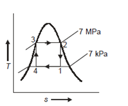
T-s representation for the Carnot cycle operating between pressure of 7MPa and 7 kPa is shown in Fig.
Enthalpy of state 1, 
=162.60+(0.6806×2409.54)

Let dryness fraction at state 4 be 
For process 4-3, 


Enthalpy at state 4, 


Thermal efficiency=
Expansion work per kg=
Compression work per kg (+ve)
(+ve)
Heat added per kg= (-ve)
(-ve)
Network per kg=(
Thermal efficiency 
Thermal efficiency 
Turbine work=969.57 kJ/kg(+ve)
Compression work=304.19 kJ/kg(-ve)
Q11) A steam power plant operates at a boiler pressure of 5 MPa, dry saturated, and a condenser pressure of 5 kPa, with steam as the working fluid. Determine the cycle efficiency for (a) Carnot cycle
(b) Rankine cycle. Also show the T-s representation for both the cycles.
A11)
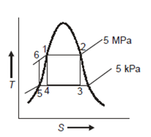
From steam tables:
At 5 MPa  ,
, 
 ,
, 
At 5 kPa
 ,
, 
 ,
, 
 As process 2-3 is isentropic, so
 Hence enthalpy at 3,
Enthalpy at 2, 
Process 1-4 is isentropic, so 


Enthalpy at 4,

Enthalpy at 1,


Carnot cycle (1-2-3-4-1) efficiency:


In Rankine cycle, 1-2-3-5-6-1,
Pump work, 


Hence 

Net work in Rankine cycle


Heat added
Rankine cycle efficiency


Q12) Why use air cycle is used in refrigeration?
A12)
• The working fluid (air) is free, environmentally friendly, safe, and non-toxic.
• Air cycle equipment is extremely dependable, lowering maintenance costs and system downtime.
• When operating outside of its design point, the performance of an air cycle unit does not deteriorate as much as that of a vapour-compression unit.
• An air cycle unit can produce heat at a useful temperature while operating in a refrigeration cycle. When combined with cooling, highly efficient, low-energy processes are possible.
• When compared to vapour-compression units, air cycle units can produce a much larger temperature difference between the hot and cold sides. That is to say:
For near-cryogenic processes, very cold air can be produced.
Heat at a useful temperature can be produced, which, when combined with cooling, can result in highly efficient, low-energy processes.
Q13) Explain The working of Reversed Carnot Cycle
A13)
The reversed Carnot cycle is an excellent refrigeration cycle where external heat sources and heat sinks are kept at a constant temperature. The diagram below depicts a reversed Carnot refrigeration system with a gas as the working fluid, as well as the cycle diagram on T-s and P-v coordinates. The cycle, as depicted, is made up of the four processes listed below:
Process 1-2: Reversible, adiabatic compression in a compressor
Process 2-3: Reversible, isothermal heat rejection in a compressor
Process 3-4: Reversible, adiabatic expansion in a turbine
Process 4-1: Reversible, isothermal heat absorption in a turbine
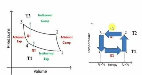
In process 1-2: There is no heat flow into or out of the refrigerator because the gas is isentropically compressed.
In process 2-3: Isothermally (T2=T3), heat is expelled into the sink (e.g., outside air).
In process 3-4: The gas expands isentropically. P4 and T4 are the pressure and temperature. At this point, heat transfer is nil.
In process 4-1: The gas expands isothermally (T4=T1), absorbing heat from its surroundings (e.g., room). This is where the cooling occurs.
Q14) Explain in short Refrigeration capacity.
A14)
The amount of heat removed from an object to be cooled by a refrigerating machine per unit time. The capacity of a refrigerator is measured in watts or kilocalories per hour. It is determined by the power of the refrigerating machinery, the temperature conditions under which it operates, and the refrigerant used. The refrigerating capacity of a vapor-compression machine is primarily determined by the volumetric capacity of the refrigerating compressor and the amount of heat required to evaporate 1 kg of refrigerant per unit time in a specific thermodynamic cycle and at a specified refrigerant boiling point and condensation temperature.
Each refrigerant has its own capacity for heat transfer. The greater its capacity, the more heat it transfers when moving at a constant rate.
Q15) Explain Unit of refrigeration in short.
A15)
Ton refrigeration, or simply tonne, is the standard unit of refrigeration, denoted by TR. It is the rate of heat transfer required to produce one tonne (2000 lbs) of ice at 32°F from 32°F water in one day, i.e., 24 hours. In British thermal units, the enthalpy of solidification of water from and at 32 F is 144 Btu/lb.

In general, 1 TR equates to 200 BTUs of heat removal per minute. Thus, if a refrigeration system can cool at a rate of 400 Btu/min, it is a two-ton machine. A machine rated at 20 tonnes can cool at a rate of 20 *200 = 4000 Btu/min. This refrigeration unit is currently in use in the United States, the United Kingdom, and India. The standard MKS unit of kcal/hr is used in many countries.


When the Btu tonne unit is expressed in SI units, the result is 210 kJ/min or 3.5 kW. The refrigeration effect is a term used in refrigeration to describe the amount of cooling produced by a system. This cooling comes at the expense of some type of energy. As a result, a term known as coefficient of performance (COP) is commonly defined as the ratio of refrigeration effect to energy input. n the MKS it can be seen that:
When the Btu tonne unit is expressed in SI units, the result is 210 kJ/min or 3.5 kW.
The refrigeration effect is a key term in refrigeration that describes the amount of cooling produced by a system. This cooling is obtained at the expense of some form of energy. As a result, it is common practise to define a term known as coefficient of performance (COP) as the ratio of refrigeration effect to energy input.
Both the refrigeration effect and the energy input should be calculated in the same unit when calculating COP.

Q16) Explain the Working of Air refrigeration Cycle.
A16)
The reverse Brayton or Joule cycle (Bell-Coleman cycle) is used in air cycle refrigeration. Heat is removed from compressed air before it is expanded to a lower temperature than before it was compressed. Work must be extracted from the air during expansion, or the entropy will increase. An expansion turbine extracts work from the air by removing energy as the expanding air drives the blades around.
This work can be used to power other devices such as generators or fans. However, it is frequently used to power a directly connected (bootstrap) compressor, which raises the compressed (hot) side pressure without additional external energy input, essentially recycling the energy removed from the expanding air to compress the high-pressure air even further.
The increase in pressure on the hot side raises the temperature even higher, causing the air cycle system to produce more usable heat (at a higher temperature). The cold air after the turbine can be used as a refrigerant either directly in an open system or indirectly in a closed system via a heat exchanger. The efficiencies of compression and expansion, as well as the heat exchangers used, limit the efficiency of such systems to a large extent.
Q17) Explain the working of Reversed Brayton Cycle
A17)
Process 1-2: Reversible, adiabatic compression in a compressor
Process 2-3: Reversible, isobaric heat rejection in a heat exchanger
Process 3-4: Reversible, adiabatic expansion in a turbine
Process 4-1: Reversible, isobaric heat absorption in a heat exchanger
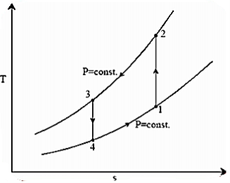
Process 1-2: Gas is compressed entropically from state 1 to state 2 at low pressure
Process 2-3: A heat exchanger rejects heat sensibly and isobarically to a heat sink as hot and high-pressure gas flows through it. Due to heat exchange, the enthalpy and temperature of the gas decrease during the process; no work transfer occurs, and the entropy of the gas decreases
Process 3-4: The high-pressure gas from the heat exchanger flows through a turbine, where it undergoes isentropic expansion and delivers network output. The temperature of the gas decreases from T 3 to T 4 during the process
Process 4-1: Cold and low-pressure gas from the turbine flows through the low temperature heat exchanger, sensibly and isobarically extracting heat from a heat source and providing a useful refrigeration effect. Due to heat exchange, the enthalpy and temperature of the gas rise during the process, no work is transferred, and the entropy of the gas increases.
Q18) Explain working of Bell-Coleman cycle
A18)
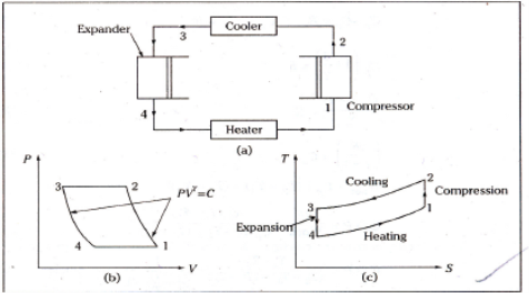
Process 1-2: The air that exits the evaporator is routed through a compressor. Where it is isentropically compressed to higher pressure and temperature.
Process 2-3: This high pressure, high temperature air is then cooled at constant pressure to a low temperature in a cooler.
Process 3-4: This high pressure, low temperature air is then expanded in an expander in an isentropic manner to lower pressure and temperature. The temperature of the air will be the lowest at point 4.
Process 4-1: This low temperature air is then passed through the heater coils, where it absorbs heat from the space to be cooled, specifically the refrigerator, and the air is heated back to the initial temperature while also cooling the refrigerator. And the cycle continues.
Q19) Explain Vapour compression refrigeration cycle
A19)
One of the many refrigeration cycles and the most widely used method for air-conditioning buildings and automobiles is vapor-compression refrigeration or vapor-compression refrigeration system (VCRS), in which the refrigerant undergoes phase changes.
Vapor-compression cycle refrigeration is a process that transfers heat from a relatively cold source to a hot medium by utilising the physics of phase change heat transfer and the unique properties of a refrigerant. Simply put, refrigeration systems move heat efficiently from a cold source to a hot heat sink (normally air). The compressor, condenser, expansion valve, and evaporator are the basic components of a refrigeration system.
The compressor is the system's beating heart. The compressor compresses a low temperature, low pressure refrigerant vapour into a high temperature, high pressure vapour. This high-temperature, high-pressure vapour then enters the condenser, where heat is removed and transferred to either air or water. The energy stored in the high-pressure gas is released as the heat is removed, and the refrigerant gives up its latent heat as it reverts to a hot liquid.
The hot, high-temperature liquid then exits the condenser and enters the expansion valve, where a pressure drops causes some of the hot gas to vaporise. The temperature of the refrigerant stream is lowered as a result. The refrigerant at the expansion valve's exit is a low temperature two-phase fluid.
This two-phase fluid enters the evaporator and comes into contact with the heat source. Through phase change heat transfer, the heat from the source boils off the refrigerant, and the low temperature, low pressure gas enters the compressor, completing the cycle.
It is beneficial to comprehend the refrigerant cycle in the depicted quadrant. Because of the high pressure, high temperature upper half, the refrigerant can become significantly hotter than ambient air, forcing heat transfer into a normally hot environment.
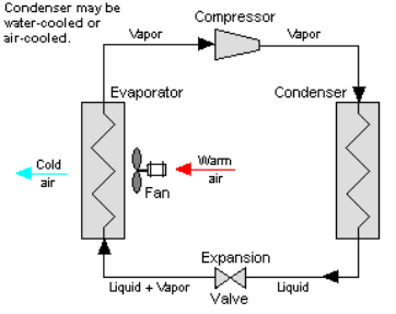
The refrigerant can absorb heat from a source that is not as hot as the environment during the low temperature, low pressure half of the cycle. The compressor works to increase pressure, and the expansion valve ensures that sufficient pressure is maintained in the condenser for heat transfer.
Cooling air, liquids, or cold plates can all be cooled using the vapour compression cycle. All that is required to accomplish this is to modify the evaporator to accommodate the cooled systems. The evaporator serves as a refrigerant to an air heat exchanger in order to create an air-cooling system. The air-cooling system is used to cool air-cooled rack-mounted equipment in buildings, automobiles, and electronics enclosures.
To cool liquid, the evaporator serves as a refrigerant once more, this time to a liquid heat exchanger, with the pumped liquid cooled by the evaporating refrigerant. The liquid cooled system is used for liquid-cooled systems such as lasers, electronics, and medical devices.
Q20) Derive the equations for Ideal Reversed Brayton Cycle
A20)
Process 1-2: Reversible, adiabatic compression in a compressor
Process 2-3: Reversible, isobaric heat rejection in a heat exchanger
Process 3-4: Reversible, adiabatic expansion in a turbine
Process 4-1: Reversible, isobaric heat absorption in a heat exchanger
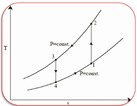


And 
Where 
Process 2-3: Hot and high-pressure gas flows through a heat exchanger and rejects heat sensibly and isobarically to a heat sink. The enthalpy and temperature of the gas drop during the process due to heat exchange, no work transfer takes place and the entropy of the gas decreases. Again, applying steady flow energy equation and second T ds equation:


Process 3-4: High pressure gas from the heat exchanger flows through a turbine, undergoes isentropic expansion and delivers net work output. The temperature of the gas drops during the process from T 3 to T 4. From steady flow energy equation:


And 
Where  pressure ratio
Process 4-1: Cold and low-pressure gas from turbine flows through the low temperature heat exchanger and extracts heat sensibly and isobarically from a heat source, providing a useful refrigeration effect. The enthalpy and temperature of the gas rise during the process due to heat exchange, no work transfer takes place and the entropy of the gas increases. Again, applying steady flow energy equation and second T ds equation:


From the above equations, it can be easily shown that

Applying 1st law of thermodynamics to the entire cycle:

The COP of the reverse Brayton cycle is given by:

Using the relation between temperature and pressures, the COP can also be written as:
