Unit - 1
Compound stress and strains
Q1) Find extension of the bar given below

Take, E = 204 GPa
A1)
A circular steel bar of following cross-sections:
Two lengths of 400 mm each of 80-mm diameter
Two lengths of300 mm each of60-mm diameter
Single length of 500 mm of 100-mm diameter

Q2) Determine value of for the figure given below,
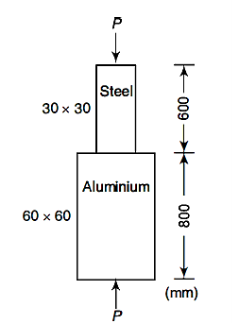
Take,
E steel = 205 GPa
E Aluminium = 75 GPa
Total decrease in length = 0.3 mm
A2)


Q3) Find the total elongation of the bar for figure given below

Take,
Diameter of steel bar = 25 mm
E = 190 GPa
A3)
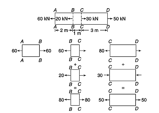
Segment AB At Section AA, the force is 60 kN tensile and for force equilibrium of this segment, it is to be
60 kN tensile at BB also.
Segment BC
Force at Section BB = 60 kN tensile (as above) + 20 kN (applied tensile force at B)
= 80 kN (tensile)
= Force at Section CC
Segment CD
Force at Section CC = 80 kN tensile (as above) - 30 kN (applied comp. Force at CC)
= 50 kN (tensile)
= Force at Section DD

Q4) Find the forces in the bar for figure given below,
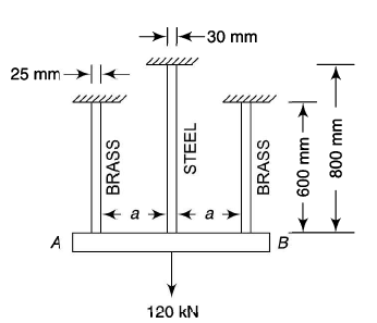
Take,
E steel /E brass = 2
A4)


Apply equilibrium,


Q5) Two parallel walls, 8 m apart, are to be stayed together by a steel rod of 30 mm diameter with the help of washers and nuts at the ends. The steel rod is passed through the metal plates and is heated. When its temperature is raised to 90° C, the nuts are tightened. Determine the pull in the bar when it is cooled to 24° C if,
The ends do not yield
Total yielding at end is 2 mm
E = 205 GPa

A5)
Area =
Pull when the ends do not yield,

Pull when the ends yield by 2 mm


Q6) A steel rod of 16-mm diameter and 3-m length pass through a copper tube of 50-mm external and 40-mm internal diameter and of the same length. The tube is closed at each end with the help of 30-mm thick steel plates which are tightened by nuts till the length of the copper tube is reduced by 0.6 mm. The temperature of the whole assembly is then raised by S6° C. Determine the stresses in the steel and copper before and after the rise of temperature. Assume that the thickness of the steel plates at the ends do not change during tightening of the nuts.


A6)
Find the area of steel & copper,


Find stresses due to tightening of nuts


Find Stress due to temperature rise


Apply compatibility equation
Temperature strain of steel + tensile strain of steel = Temperature strain of copper - compressive strain of copper


Find Final stresses


Q7) A steel bar 35 mm X 35 mm in section and I 00 mm in length is acted upon by a tensile load of 180 kN along its longitudinal axis and 400 kN and 300 kN along the axes of the lateral surfaces.
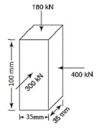
(i) change in the dimensions of the bar
(ii) change in volume
(iii) longitudinal axial load acting alone to produce the same longitudinal strain as in,
E =205 GPa, 
A7)
- Determination of change in dimensions
Total strain in x direction = 
Total strain in y direction = 
Total strain in z direction = 
- Find change in volume
- Find Longitudinal axial load


Longitudinal axial load = 
Q8) A bar of 24-mm diameter and 400-mm length is acted upon by an axial load of 38 kN. The elongation of the bar and the change in diameter are measured as 0.1 65 mm and 0.0031 mm respectively.
Determine
(i) the Poisson's ratio (ii) the values of the three moduli
A8)
Use,
Poisson ratio equation


Q9) Two pieces of wood of section 50 mm X 30 mm are joined together along a plane at 60° with the x-axis. If the required strength of the joint is to be 7.5 MPa in tension and 4 MPa in shear, determine the maximum force which the member can sustain.
A9)
Strength of joint in tension
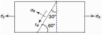


Strength of joint in shear


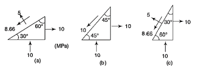
Q10) A rectangular block is subjected to two perpendicular stresses of 10 MPa tension and 10 Mpa compression. Determine the stresses on planes inclined at (i) 30°, (ii) 45°, and (iii) 60° with the plane of compressive stress.
A10)
Plane at 30 Degree with  ,
,


Plane at 45 Degree with  ,
,


Plane at 60 Degree with  ,
,


Q11) Explain general classification of Stresses in a beam.
A11) The generalized classification of stresses is as follows:
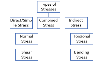
- Normal Stress:
Stress induced due to forces which are acting normal to the cross-sectional area of the section or beam is called Normal stress.
Normal Stresses are further classified as Tensile and Compressive Stresses.
- Tensile Stress: When a section is subjected to two equal and opposite pulls due to which body tends to increase in length as shown in fig., the stresses induced are called Tensile Stresses. As a result of the tensile stress, the cross-sectional area of the section decreases.

- Compressive Stress: When a section is subjected to two equal and opposite pushes due to which body tends to decrease in length as shown in fig., the stresses induced are called Compressive Stresses. As a result of the compressive stress, the cross-sectional area of the section increases.

- Shear Stress:
When two equal and opposite parallel forces which are not in the same line, act on two parts of the body, then these parts tend to slide over or shear from each other across any section and the stress developed during this process is termed as Shear Stress. Thus these stresses are produced when the forces act tangentially to the cross-sectional area.
- Torsional Stress:
This is a type of indirect stress produced due to twisting moment applied to circular cross-section about its axis.
- Bending Stress:
Bending stresses are the stresses that are induced normally at a particular point in the body which is subjected to loads that causes the body to bend. When the loads are applied perpendicular to the axis of the beam, bending moment is induced in the beam.
Q12) Define the following terms:
- Poisson’s Ratio
- Hooke’s Law
- Modulus of Elasticity
- Modulus of Rigidity
A12)
Poisson’s Ratio:
When a particular bar is loaded in Tension, the axial elongation is accompanied with lateral contraction (i.e. contraction normal to the direction of applied load). The lateral strain at any point in a bar is proportional to the axial strain at that same point if the material is linearly elastic. The ratio of these strains is a property of the material known as Poisson’s ratio. This dimensionless ratio, usually denoted by the Greek letter ν (nu), can be expressed by the equation

Here negative sign indicates opposite directions or signs for strains. ν is assumed same in Tension as well as Compression. Some values of ν are 0.1 for concrete, 0.5 for rubber and approx. 0 for cork.
Hooke’s law:
Robert Hooke was the first person to investigate scientifically, the elastic properties of material and tested using diverse materials like wood, metal, stone, bones etc. He found out that the lengthening of wires was in some sort of proportions to that of the weights applied and stated as “When a material is loaded, within its elastic limit, the stress is proportional to the strain”. Mathematically represented as,

It should be noted that Hooke’s law holds good for tensile as well as compressive loads. E given here is known as Modulus of Elasticity or Young’s Modulus.
Modulus of Elasticity:
We know that by using Hooke’s law i.e.
Stress  Strain

This constant of proportionality (E) is known as Modulus of Elasticity or Young’s Modulus. Numerically, Modulus of Elasticity is that value of tensile stress, which when applied to uniform bar will increase its length by unit value of strain. As the strain is dimensionless, the units of Young’s Modulus are same as that of Stress, i.e. Pascal (Pa) or N/m2. This Young’s Modulus is also the slope of stress-strain curve in elastic region that will be discussed later.
Some of the values of E are, Steel = 200-220 GPa, Wrought Iron = 190-200 GPa, Aluminium = 60-80 GPa.
Modulus of Rigidity:
It is experimentally found that, within the elastic limit of the material, shear stress is always directly proportional to the shear strain. Mathematically, it is written as,
Where C = Constant of proportionality known as Modulus of Rigidity or shear modulus.
- Derive the relation between Young’s Modulus and Bulk Modulus:
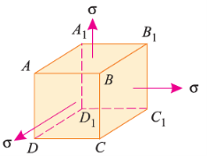
Consider a cube ABCDA1B1C1D1 as shown in fig. Let the cube be subjected to three mutually perpendicular stresses of same intensity.
Here,  = Tensile stresses
 = length of cube
E = Young’s modulus of the cube material.
Now, we will consider deformation of any one particular side (say AB). Here, this deformation will be caused by,
- Tensile stresses on faces BB1CC1 and AA1DD1.
- Compressive stresses on faces AA1BB1 and DD1CC1.
- Compressive stresses on faces ABCD and A1B1C1D1.
The tensile stress mentioned above will result in longitudinal strain of  /E. The compressive stresses will result in lateral strain of [ν*(
 /E)], where ν = Poisson’s ratio.
Thus, the total strain produced is given as,


Now, the volume of cube is  3, thus
 3
3
Differentiating with respect to  , we get,


Now, replacing the value of  mentioned above.


Now, replacing  3 by
3 by  ,
,

Replacing  by
by  , we get,


The above equation gives relation between Young’s Modulus (E), and Bulk Modulus (K).
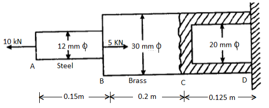
Q13) The diameters of the brass and steel segments of the axially loaded bar shown in figure are 30 mm and 12 mm respectively. The diameter of the hollow section of the brass segment is 20 mm.
Determine: (i) The maximum normal stress in the steel and brass (ii) The displacement of the free end; Take Es = 210 GN/m2 and Eb = 105 GN/m2
A13)


 The maximum normal stress in steel and brass


(ii) the displacement of the free end


Q14) A Copper rod 6 cm in diameter is placed within a steel tube, 8 cm external diameter and 6 cm internal diameter, of exactly the same length. The two pieces are rigidly fixed together by two transverse pins 20 mm in diameter, one at each end passing through both rod and the tube. Calculate the stresses induced in the copper rod, steel tube and the pins if the temperature of the combination is raised by 50oC. [Take ES=210 GPa, αs =0.0000115 /oC; Ec=105 GPa, αc = 0.000017 /oC]

A14)

Area of copper rod( )
)
Area of steel tube( )
)
Rise in temperature, t=50°C
Free expansion of copper bar =
Free expansion of steel tube
Difference in free expansion =
A compressive force(P) exerted by the steel tube on the copper rod opposed the extra expansion of the copper rod and the copper rod exerts an equal tensile force P to pull the steel tube. In this combined effect reduction in copper rod and increase in length of steel tube equalize the difference in free expansions of the combined system. Reduction in the length of copper rod due to force P Newton

Increase in length of steel tube due to force P

Difference in length is equated


Or P=49.695 kN
Stress in copper rod 
Stress in steel tube 
Since each of the pin is in double shear, shear stress in pins 

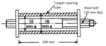
Q15) The steel bolt shown in Figure has a thread pitch of 1.6 mm. If the nut is initially tightened up by hand so as to cause no stress in the copper spacing tube, calculate the stresses induced in the tube and in the bolt if a spanner is then used to turn the nut through 90°.Take Ec and Es as 100 GPa and 209 GPa respectively.
A15)
Stresses induce in the tube and the bolt  :
:


Tensile force on steel bolt  compressive force in copper tube
Also, Increase in length of bolt + decrease in length of tube = axial displacement of nut


 and
and 
Q16) Find the stresses in three parts and total extension of the bar under an axial pull of 40 kN. Take E = 2 × 10⁵ N/mm2.

A16)


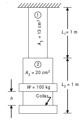
Q17) A vertical rod 2 m long, fixed at the upper end, is 13 cm2 in area for 1 m and 20 cm2 in area for another 1 m. A collar is attached to the free end. Through what height can a load of 100 kg fall on to the collar to cause a maximum stress of 50 N/mm2?
A17)
Let, W=Falling weight, and  equivalent gradually applied load which produces same maximum stress and extension as it causes due to falling load W
Total extension 


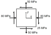
Q18) The state of plane stress at a point is represented by the stress element below. Determine the principal stresses and draw the corresponding stress element.
A18)
Given:


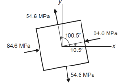
But we check we angle goes with which principal axis


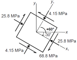
Q19) The state of plane stress at a point is represented by the stress element below. Determine the stresses acting on an element oriented 30 degrees clockwise with respect to the original element.
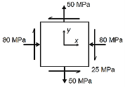
A19)
Given:


Q20) Describe the Principal stresses and Principal plane.
A20)
Principal stresses and principal plane
The magnitude of normal stress and shear stress may vary with respect to the inclination of planes. If we are concerned with the safety of solids under stress, we are required to find on which planes extreme values of normal and shear stress components are present. Hence, it is essential to know:
(a) Maximum tensile stress,
(b) Maximum compressive stress, and
(c) Maximum shear stress.
The extreme values of normal stresses are called the Principal Stresses and the planes on which the principal stresses act is called the principal planes.
In two-dimensional problems, there are two principal stresses, namely the major principal stress and the minor principal stress which are defined as the maximum and minimum values of the normal stresses respectively. Here, the maximum or minimum is to be considered algebraically.
For example, if the principal stresses happen to be 20 N/mm2 tensile and 75 N/mm2 compressive, the tensile stress of 20 N/mm2 is to be taken as the major principal stress denoted by the symbol σ1 and the compressive stress of 75 N/mm2 is to be taken as the minor principal stress (algebraically – 75 N/mm2) and denoted by the symbol σ2. The corresponding planes are defined as major and minor principal planes.
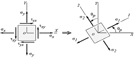
Fig: Principal Stress
Expressions of Principal Planes and Principal Stresses:
In calculus, you have learnt that when a function reaches maximum or minimum its derivative with respect to the independent variable becomes zero. Since the normal stress on an arbitrary plane is a function of the aspect angle θ as given by the expression,

Expression for major and minor principal stresses as follows

Above equations may be used to readily determine the principal planes and principal stresses.

