Unit - 2
Stresses in Beams, Deflection of beams and Torsion
Q1) What is the theory of Pure Bending?
A1) Consider small length dx of a simply supported beam subjected to a bending moment M. Now, let us consider any two sections viz. AB and CD that will be perpendicular to the axis of beam RS. Due to action of bending moment, the beam as a whole will bend as shown in Fig.(b).
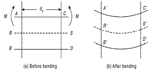
As seen in fig, the top layer ‘AC’ has gone into compression and decreased to A´C´. Layer RS has suffered no change in length, though bent to R´S´. Lower most layer BD has been stretched to B´ D´. Hence layers above RS have been compressed and those below RS have been stretched. This layer RS, neither goes into tension nor compression is also called as Neutral plane or Neutral layer.
The above-mentioned theory is also known as “Theory of Simple Bending”.
- Derive the Flexural formula.
We know that on one side of the neutral axis there are tensile type of stresses while on the other, there are compressive type of stresses. Couple is formed by these types of stresses, whose moment should be equal to external moment created(M). The moment of this type of couple, which opposes the external bending moment, is known as the moment of resistance.
Now, let’s consider a section or part of the beam shown in below. Let the neutral axis of the section denoted by NA. Now consider a small layer PQ of the beam section at a distance y from the neutral axis as shown in Fig. Below.
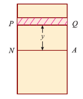
Let δ A = Area of the layer PQ.


Thus, the total stress is given by,

Moment of this total stress about neutral axis is given by,


Here the algebraic sum of all the moments present about the neutral axis should be equal to M. Therefore


The expression  represents the moment of inertia of area of the complete section about the neutral axis. Therefore,

Where I= moment of inertia,
We know that,

Therefore,

The above equation is also known as Bernoulli-Euler bending equation or Flexural Formula.
2. Derive the differential equation for bending.
Consider a small portion PQ of a beam, bent into an arc (As shown in Fig.)
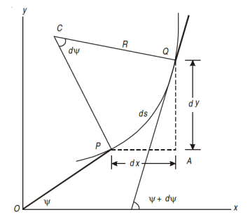
Let,
Ds = Length of beam PQ
R = Radius of the arc, into which the beam has been bent
C = Centre of the arc
Ds = Length of the beam PQ
R = Radius of the arc, into which the beam has been bent.
ψ = Angle, which the tangent at P makes with x – x axis, and
ψ + dψ = Angle which the tangent at θ makes with x – x axis
From the geometry of figure, we get,
∠PCQ = dψ
Ds = R *dψ
Considering ds = dx

We know that if x and y be the co-ordinates of point P, then

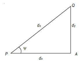
As  is small, tan
 =
=
Differentiating, we get,

We know that,


Substituting the value of (1/R), we get,

i.e.

The above-mentioned equation is known as Differential equation for bending, which also gives the relation between slope, deflection and radius of curvature.
Q2) Explain in steps the procedure of solving slope and deflection numerical using Macaulay’s Method.
A2) The Macaulay’s method is explained as following.
1. This method is similar to double integration method.
2. It is used to find the slope and deflection at any point on the beam.
3. In this method, bending moment at any section is expressed in systematic order.
4. The section x is to be taken in the last portion of the beam.
5. In this method, bending moment of each force or U.D.L. Is separated by a compartment of lines.
6. Integrating bending moment equation, we will get slope equation.
7. Again integrating slope equation, we will get deflection equation.
For example, consider a beam subjected to loading as shown in Fig. Below.
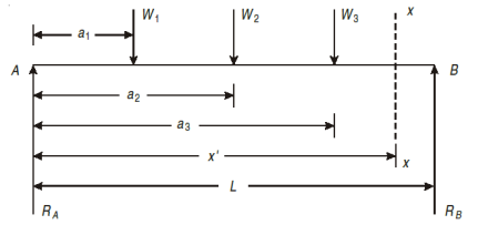
Step I. Determine the support reactions.
Step II. Consider a section x – x at a distance x covering all the loads from left end of the beam.
Step III. Take moment of all forces about section x – x, considering sagging B.M. As positive and hogging as negative.

Step IV. Use differential equation of deflection
i.e.

Step V. Integrating above equation, we get;

Step VI. Again, integrating above equation, we get

Step VII. The constant of integration c1 and c2 are calculated by applying boundary conditions.
Step VIII. Substituting the value of constant, in equation obtained in step V gives general equation for slope and equation in step VI gives general equation for deflection.
Q3) A simply supported beam of length 8 m carries two concentrated loads of 64 kN and 48 kN magnitude in downward direction at distances of 1 m and 4 m from left end. Find the deflection below the 48 kN load. Take E = 210 GPa and I = 180 × 106 mm4.
A3)
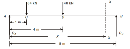
Let support’s reactions be  and
and 
For 
For 


Using Macaulay’s method
Consider a section x-x at a distance x from support A

 (iii)
(iii)
Integrating 
Again integrating  (iv)
(iv)
Applying boundary conditions: when x=0, y=0

When 


Substituting the value of  and
and in eqs(iii) and (iv)
Deflection equation, 
Deflection below 48 kN load, ie x=4m

Flexural rigidity, 


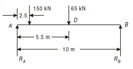
Q4) A beam of uniform section, 10 m long is simply supported at the ends. It carries point loads of 150 kN and 65 kN at distances of 2.5 m and 5.5 m respectively from the left end. Calculate.
(i) Deflection under each load, (ii) Maximum deflection
A4)
For support reactions:


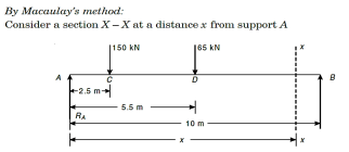
Moment about section X-X;
 (i)
(i)
Integrating the above equation we get
 (ii)
(ii)
Again integrating eq(ii) We get
 (iii)
(iii)
To find constants of integration ie  and
and  applying boundary condition
(i) when  put in eq (ii);
(ii) When  , put in eq (iii)


Substituting the values of  and
and  in eq(ii) and (iii) we get slope equation,


Deflection equation

Deflection at C ie under 150kN
Put in deflection equation


Deflection at D ie. Under  , put
, put  in deflection equation


Location of point of maximum deflection
Maximum deflection occurs at the point where slope is zero. Assume maximum deflection lies between C and D. 


Maximum deflection at 


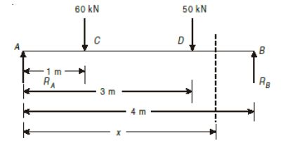
Q5) A beam, simply supported at ends A and B is located with two-point loads of 60 kN and 50 kN at distance 1 metre and 3 metre respectively from end A. Determine the position and magnitude of maximum deflection. Take E = 2 × 10⁵ N/mm2 and I = 8500 cm4.
A5)


Flexural rigidity, 


Assume span of the beam, L=4m
To calculate support reactions. For  we have


For  =0 we have


Using Macaulay’s method for deflection
Consider a section X-X at a distance x from support A.
 (i)
(i)
Integrating the above eq(i)
 (ii)
(ii)
Integrating the above eq (ii)
 (iii)
(iii)
Applying boundry conditions to find the constants  and
and 
(i) when 

(ii) When  put in eq(iii)


Slope equation

Location of maximum deflection
Maximum deflection occurs at a point where slope is zero from the fig.
4.12 it will be occurred between CD portion
Consider slope equation upto AD only.


Deflection equation


Q6) A Simply supported beam AB of span length 4 m supports a uniformly distributed load of intensity q = 4 kN/m spread over the entire span and a concentrated load P = 2 kN placed at a distance of 1.5 m from left end A. The beam is constructed of a rectangular cross-section with width b = 10 cm and depth d = 20 cm. Determine the maximum tensile and compressive stresses developed in the beam to bending.
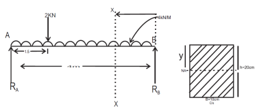
A6)
 (i)
(i)
 (ii)
(ii)


If 

 (iii)
(iii)
From (i) and (ii) we find out that bending movement at  in(i) gives maximum bending movement
Just find  for both the cases

Area movement of Inertial (I) 
Maximum distance from  is
is 

Therefore, maximum tensile stress in the lowest point in the beam is 14.355 MPa and maximum compressive stress in the topmost fiber of the beam is 14.355 MPa
Q7) A cantilever of circular solid cross-section is fixed at one end and carries a concentrated load P at the free end. The diameter at the free end is 200 mm and increases uniformly to 400 mm at the fixed end over a length of 2 m. At what distance from the free end will the bending stresses in the cantilever be maximum? Also calculate the value of the maximum bending stress if the concentrated load P = 30 kN.
A7)
We have 


From equation (i) we have


Taking distance x from the free end we have


Let d be the diameter at x from free end
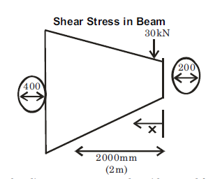


Hence maximum bending stress occurs at the midway and from eq(ii), maximum bendign stress


Q8) A timber beam 15 cm wide and 20 cm deep carries uniformly distributed load over a span of 4 m and is simply supported. If the permissible stresses are 30 N/mm2 longitudinally and 3 N/mm2 transverse shear, calculate the maximum load which can be carried by the timber beam.

A8)
Moment of Inertial 
Distance of neutral axis from the top surface 
We know that 
Where maximum bending moment due to uniformly distributed load in simply supported beam(M)
Considering longitudinal stress


Now considering shear
Maximum shear force
Therefore average shear stress 
For rectangular cross-seciton
Maximum shear stress (
Now 
=40kN/m
So maximum load carrying capacity of the beam =15kN/m (without fail)
Q9) A hollow steel shaft transmits 200 kW of power at 150 rpm. The total angle of twist in a length of 5 m of the shaft is 3o. Find the inner and outer diameters of the shaft if the permissible shear stress is 60 MPa. Take G = 80 GPa.
A9)
Given P=200kW N=150 rpm
l=5m =60 MPa
G=80GPa θ=
To find Outer and inner diameters of hollow shaft D and d
Torque

From angle of twist limit


From maximum shear stress limit


Inner and Outer diameter
From (i) and (ii) 900605 D=129×

Q10) Compare the length of equal length of a solid and a hollow shaft to transmit a given torque for the same maximum stress if the inside diameter of shaft is three fourth of the outside.
A10)
Given solid and hollow shafts of equal length, transmitting same torque, same maximum stress Inner diameter=3D/4
To find to compare weights of two shafts
For solid shaft

For hollow shaft

Equating the two
As the shafts transmits a given torque for the same maximum stress, ie T/ is the same
Equating (i) and (ii) 
Ratio of weights
Ratio of weights of equal lengths 

Q11) Figure shows a stepped steel shaft. It is subjected to a torque T at the free end and a torque 2T in the opposite direction at the junction of two sizes. Determine the total angle of twist if the maximum shear stress is limited to 80 MPa. G = 80 GPa.

A11)
Given a stepped steel shaft as shown in fig.

To find Total angle of twist
Torque in the portion BC=T (counter-clockwise)
Torque in the portion AB=T-2T (counter-clockwise) or (T-clockwise)
Thus the two portions of the shaft are subjected to a torque of same magnitude but in the opposite direction.
Maximum stress will reach the maximum value in the thinner portion first.

Angle of twist


Q12) Figure shows a hollow shaft. Determine the maximum power transmitted by shaft at 200 rpm if the shear stress in the shaft is nit to exceed 70 MPa. Also find the lengths of the two portions if the twist produced in the two portions of the shaft are equal.
A12)
Given A hollow shaft as shown in fig.

To find
Maximum power
As  the maximum value of shear stress will reach in the portion in which d is higher.
The maximum torque transmitted,


Lengths of two portions
If twist is to be same in the two portions,


Q13) A circular steel shaft of 40 mm diameter is provided with enlarged portion of 80 mm diameters at two ends as shown in fig. On the enlarged portion a steel tube of 2 mm thickness is shrunk. During the shrunk process, the 40 mm diameter shaft is held twisted by a couple of magnitude of 800 N.m. When the tube is firmly set on the tube, the couple is removed. Determine the twisting couple left on the shaft if the tube and the shaft are made of same material.
A13)

Given A compound steel shaft as shown in fig. 10.8. The shaft is twisted by a couple of 800 Nm and then tube is shrunk.
To find twisting couple left on the shaft\
For the shaft, 
For the tube
Initial angle of twist of shaft
Initially let θ be the angle of twist in the shaft, then 
On removing the twisting couple
Let T be the residual twisting couple on the shaft which will also be equal to the acting on the tube
 residual angle of twist in the shaft


Equating the total angles of twist
As total angle of twist after removal of couple must be equal to the initial angle of twist


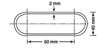
Q14) A thin walled 800 mm long member has the cross-section as shown in the fig. Determine: i) the maximum torque if the angle carried by the section is limited to 4o and ii) the maximum shear stress induced for the maximum torque G = 82 GPa
A14)
A thin-walled member as shown in fig.

To find
Maximum torque
Maximum shear stress

Maximum torque

T=2690×
Maximum shear stress


Q15) A solid shaft of 150mm diameter is used to transmit torque. Find the maximum torque transmitted by the shaft If the maximum shear stress induced to the shaft is 45 N/mm^2.
A15)
Given:
Diameter of the shaft, D=150mm
Maximum shear stress, =45 N/mm2
Let T = Maximum torque transmitted by the shaft.
Using equation (16.4), 

Q16) The shearing stress in the solid shaft is not to exceed 40N/mm^2 when the torque transmitted is 20000N-m. Determine the minimum diameter of the shaft.
A16)
Given:
Maximum shear stress, 
Torque transmitted, 
Let  Minimum diameter of the shaft in mm.


Q17) A solid steel shaft has to transmit 75KW at 200 rpm. Taking allowable shear stress as 70 N/mm2, find suitable diameter of the shaft, if the maximum torque transmitted at each revolution exceeds the mean by 30%.
A17)
Given:
Power transmitted, 
R.P.M of the shaft, 
Shear stress, 
Let  Mean torque transmitted
 Maximum torque transmitted =1.3T
 Suitable diameter of the shaft
Power is given by the relation,


Maximum torque transmitted by a solid shaft is given by equation (16.4) as


Q18) A hollow shaft is to transmit 300 KW power at 80 r.p.m. If the shear stress is not to exceed 60N/mm2 and internal diameter is 0.6 of the external diameters, find the external and internal diameter assuming that the maximum torque is 1.4 times the mean.
A18)
Given:
Power transmitted, 
Speed of the shaft, 
Maximum shear stress, 
Internal diameter, 
Maximum torque,  times the mean torque =1.4×T
Power is given by the relation,


Now maximum torque transmitted by hollow shaft is given as-


Q19) Determine the diameter of the solid steel shaft which will transmit 90KW at 160 r.p.m. Also determine the length of the shaft if the twist must not exceed with 1 degree over the entire length. The maximum shear stress is limited to 60 N/mm^2. Take C = 8 * 10^4 N/mm^2.
A19)
Given:
Power,
Speed, 
Angle of twist, 
Maximum shear stress, =60 N/
Modulus of rigidity, 
Let  Diameter of the shaft and
 Length of the shaft
(i) Diameter of the shaft
Using equation


Now using equation


(ii) Length of the shaft
Using equation, 


Q20) A circular solid shaft transmit 75 KW power at 200 r.p.m. Calculate the shaft diameter, if the twist in the shaft is not to exceed 1 degree in 2m length of shaft and shear stress is limited to 50N/mm^2. Take: Modulus rigidity, 
A20)
Given:
Power transmitted, 
Speed of the shaft, 
Twist in the shaft, 
Length of shaft, 
Maximum shear stress, 
Modulus of rigidity, 


(i) Diameter of the shaft when maximum shear stress is limited to 50


(ii) Diameter of the shaft when the twist in the shaft is not to exceed 1


The suitable diameter of the shaft is the greater value of the diameter given by equation (i) and (ii) i.e., 80.4mm say 81 mm.
Q21) Determine the diameter of the solid shaft which transmit power of 30KW at 250 r.p.m. The maximum shear stress should not exceed 30  and twist should not be more that 1 degree in a shaft length of 2 m.
A21)
Given:
Power,
Speed, 
Maximum shear stress, =30 N/
Twist in the shaft, 
Length of shaft, 
Modulus of rigidity, 


(i) Diameter of the shaft when maximum shear stress

Maximum torque transmitted by a solid shaft is given by equation


 …….(i)
(ii) Diameter of the shaft when the twist in the shaft is not be more than 1

Where J =Polar moment of inertia of solid shaft


The suitable diameter of the shaft is the greater* of the two values given by equations (i) and (ii).
 Diameter of the shaft =124.5mm say 125 mm.
*If diameter is taken smaller of the two values say 107.5mm, then from equation.
 , the value of shear stress will be
 , the value of shear stress will be


Which is more than the given value of 30N/mm2).