Unit - 3
Helical and Leaf Springs
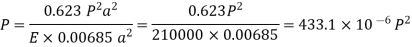
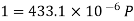
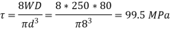
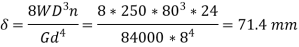
Q1) A dose-coiled helical spring having 24 turns is made of 8-mm diameter wire. The mean diameter of the spring is 80 mm, and it carries a load of 250 N. Determine the shear stress developed, the deflection and the stiffness of the spring. Take G = 84 GPa.
A1)
Shear stress
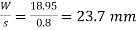
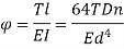
Deflection
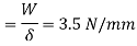
Stiffness
Q2) A close-coiled helical spring carries a load of 400 N. Its mean coil diameter is I0 times the wire diameter. Determine these diameters if the maximum value of shear stress in the spring is not to exceed 75 Mpa.
A2)
As, D =10 d

So, d =11.65 mm
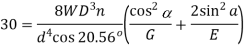
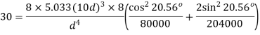
Q3) A safety valve of 120-mm diameter is designed to blow off at a gauge pressure of I MPa. A close coiled helical spring of 160 mm mean diameter is used to hold the valve in position. Determine the diameter of the coils of the spring and the number of turns required if the initial compression of the spring is 60 mm and the maximum value of shear stress is 70 MPa. G = 84 GPa.
A3)
Determination of load,
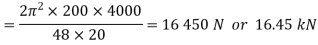
Force on the spring W = Pie/4 * 120^2 *1 = 11310 N
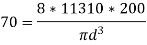
Wire Diameter.


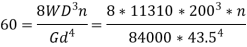
Number of coils,
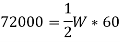
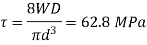
Q4) A close coiled helical spring absorbs 72 N.m of energy when compressed through 60 mm. There are 8 coils in the spring. The coil diameter is IO times the wire diameter. Find the diameters of the coil and wire and the maximum shear stress. G = 82 GPa.
A4)


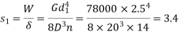
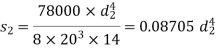
Q5) A composite spring consists of two dose-coiled helical springs connected in series. Each spring has 14 coils at a mean diameter of 20 mm. The stiffness of the composite spring is 800 Nm. If the wire diameter of one spring is 2.5 mm, find the wire diameter of the other. What will be the maximum load which can be carried by the composite spring and the corresponding deflection for a maximum shear stress of 150 MPa! G = 78 GPa.
A5)
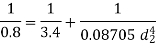
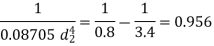
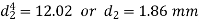
Determination of wire diameter
For springs in series, 
Load and deflection
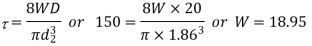
Load and deflection
Total deflection
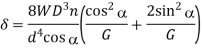
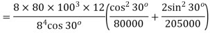
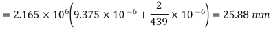
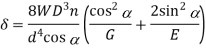
Q6) An open-coiled helical spring has 12 turns wound to a mean diameter of I 00 mm. The angle of the coils with a plane perpendicular to the axis of the coil is 30°. The wire diameter is 8 mm.
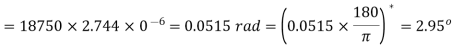
Determine The axial tension with a load of 80 N & the angle turned by the free end if free to rotate
E =205 GPa & G =80 GPa
A6)
Axial extension
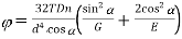
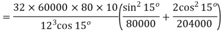
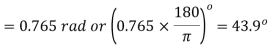
Angle turned

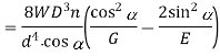
Q7) An open-coiled helical spring has I0 coils and is made out of a 12 mm diameter steel rod. The mean diameter of the coils is 80 mm and the helix angle I 5°. Find the deflection under an axial load of 250 N. What are the maximum intensities of direct and shear stresses induced in the section of the wire! If the above axial load is replaced by an axial torque of 60 N · m, determine the axial deflection and the angle of rotation about the axis of the coil. G = 80 MPa and E = 204 GPa.
A7)
For axial load
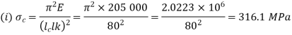
(i) 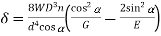
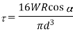
= =28.47 MPa
Principal stresses=
Maximum shear stress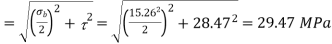
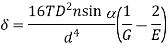
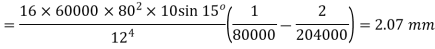
For axial torque
If axial is replaced by an axial torque of 60 Nm
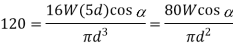
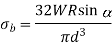
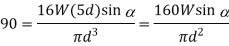
Q8) In an open-coiled helical spring, the stresses due to twisting and bending are 120 MPa and 90 Mpa respectively when the spring is loaded axially. The springs consists of 8 coils and the mean diameter of the coils is I0 times the diameter of the wire. Determine the maximum permissible load and the diameter of wire for a maximum deflection of 30 mm. G = 80 GPa and E = 204 GPa.
A8)
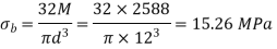
Bending and shear stress constraints
Dividing (ii) by (i) 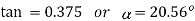
From (i) 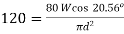

Deflection constraints


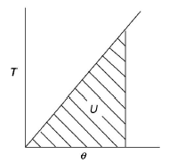
Q9) Explain the deflection of springs by energy method
A9)
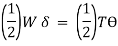
Strain energy stored in beam is,

Strain energy in torsion,

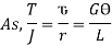
For solid shaft,


Therefore,

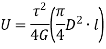
This is Strain energy over the whole shaft. However, the shear stress varies from zero at the axis to maximum at outer surface. So, intensity of strain energy is also not uniform and varies across the cross section.
Thus, total strain energy,


Under axial Load:

Under axial Torque/ Twist:
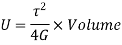
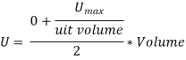
Maximum strain energy/ Unit volume

Total strain energy due to bending moment,

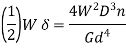
Equating,
Q10) Differentiate between open & close helical spring
A10)
Open Coiled Helical Springs: These helical springs are designed to resist compression, which is they are known as compression springs. These springs are not wound tightly and have a high pitch. This results in large spaces between the coils, which also makes the springs very recognizable. Hence, no two turns of a spring will lie on the same axis of the helix. The turns of these springs are located at inclined angles towards the helical axis. Some typical applications include ball point pens, valve assemblies in engines, car suspension systems, pogo sticks, etc.
Closed Coiled Helical Springs: Designed to resist stretching and twisting, these springs are also known as tension/extension springs. These springs feature an eye or a hook at the end for attachment. These springs can endure stress caused by high torsion or bending. The coils are closely wound to each other and lie on the same axis of the helix. The turns of this spring lie at 90 degrees to the axis of the helix. These springs are used for heavy duty applications such as carburetors, garage door assemblies, vice-grip pilers, etc.
Q11) Explain Buckling & Stability.
A11)
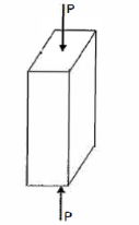
A member of a structure that is subjected to axial Compressive load is referred to as a column or strut. The member is known as a column if it is vertical and both of its ends are permanently attached while subjected to axial compressive load, such as a vertical pillar between the roof and the floor. A strut is a structural element that is not vertical and has both ends hinged or pin connected. Struts, connecting rods, and piston rods are examples of struts.
The failure of a column takes place due to the anyone of the following stresses set up:
- Direct compressive stress
- Buckling stress
- Combined stress
Failure of Short Column:

If the compressive load on the short column is gradually increased, a stage will reach when the column will be on the point of failure by crushing. The stress induced in the column corresponding to this load is known as crushing stress and the load is called crushing load.
 = Crushing load,
 = Crushing stress, and
A = Area of cross-section.

All short columns fail due to crushing.
Failure of long Column:
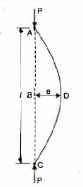
The load at which the column just buckles, is known as buckling load or critical just or crippling load. The buckling load is less than the crushing load for a long column. The value of buckling load for long columns is low whereas for short columns the value of buckling load is relatively high.
Let,
l = Length of a long column
P = Load (compressive) at which the column has just buckled
A = Cross-sectional area of the column
e = Maximum bending of the column at the center
 = Stress due to direct load =
 = Stress due to bending at the center of the column =
Z = Section modulus about the axis of bending.
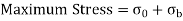
The extreme stresses on the mid-section are given by,
The column will fail when maximum stress is more than the crushing stress. But in case of long columns, the direct compressive stresses are negligible as compared to buckling stresses. Hence very long columns are subjected to buckling stresses only.
Q12) What are the assumptions in Euler's column theory?
A12)
- The column is initially perfectly straight, and the load is applied axially.
- The cross-section of the column is ·uniform throughout its length.
- The column material is perfectly elastic, homogeneous, and isotropic and obeys Hooke's law.
- The length of the column is very large as compared to its lateral dimensions.
- The direct stress is very small as compared to the bending stress.
- The column will fail by buckling alone.
- The self-weight of column is negligible.
Q13) Explain & Derive Slenderness ratio
A13)
Critical load is the only load for which the structure will be in equilibrium in the disturbed position. If the load on the strut or column exceeds this value, then the column will fail by buckling. At this value the structure is in equilibrium regardless of the magnitude of the angle. At this value, restoring effect of the moment in the spring matches the buckling effect of the axial load represents the boundary between the stable and unstable conditions.
If the axial load is less than Pcr the effect of the moment in the spring dominates and the structure returns to the vertical position after a small disturbance – stable condition.
If the axial load is larger than Pcr the effect of the axial force predominates and the structure buckles – unstable condition.
Because of the large deflection caused by buckling, the least moment of inertia I can be expressed as,

Where, A is cross-sectional area of column or strut.
K is the radius of gyration and is given by

Note: The smallest radius of gyration of the column, i.e., the least moment of inertia I should be taken in order to find the critical stress.
According to Euler’s Theory, Euler’s critical load is given by,

Where,  is Equivalent length of column (1st mode of bending)
Slenderness Ratio is referred as the ratio between the length and least radius of gyration.
It is denoted by 

We have,

And

Therefore,


Q14) Explain & Derive Ranking Gordon formulae
A14)
Euler’s formula is applicable to long columns in which l/k ratio is larger than a certain value for a particular material. Also, direct compressive shear is not considered, therefore it gives correct result for very long columns only. For columns of medium length Rankine formula is used where results are not accurate according to Euler’s formula.


- For Long columns
 is very small,
- For short columns
 is very large,

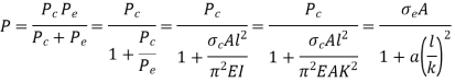
Were,
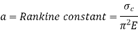

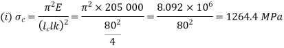
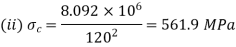
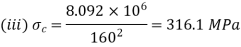
Q15) Using Euler’s Formula, determine the critical stresses for the strut of slenderness ratio 80,120, 160 and 200 under a condition of (a) both ends hinged and (b) both ends fixed. Take E = 205 GPa.
A15)
Given A strut with slenderness ration 80, 120, 160 and 200 and with both ends highed and both ends fixed.
To find critical stresses
Both ends hinged
For both ends hinged 

(ii) 
(iii) 
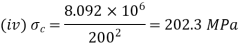
(iv) 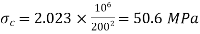
Both ends fixed


Q16) A 4 m long hollow alloy tube with inside and outside diameter are 36 mm and 48 mm elongates by 3 mm under a tensile force of 50 kN. Determine the buckling load for the tube when it is used as a column with both ends pinned and with factor of safety 5.
A16)
Given a hollow alloy tube


To find Buckling load when used as column with both ends pinned
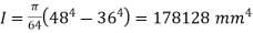
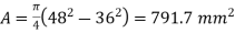 ;
; 
When used as a bar
When used as a column 
Safe load 
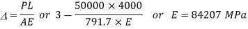
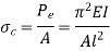
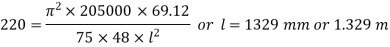
Q17) Determine the shortest length for a pin-joined steel column of cross-section 75 mm x 48 mm using Euler’s Formula. Take critical stress value as 220 MPa and E = 205 MPa.
A17)
Given a pin-jointed column of cross –section 75 mm×48 mm
To find shortest length
Least moment of inertial of the section 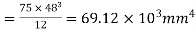
Determination of shortest length
Q18) A 4 m log circular bar deflects 20 mm at the center when used as simply supported beam under a 200 N load at center. Determine critical load for the same bar when used as a strut which is firmly fixed at one end and pin joined at other.
A18)
Given a circular simply supported beam

To find critical load if used a strut with one end fixed and other pin-jointed
Bar as abeam
Deflection due to central load, 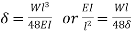
Bar as a strut
Euler load, 
Q19) Using Euler's formula, determine the critical stresses for a strut of slenderness ratio 80, 120 and 160 and 200 under the condition of (a) both ends hinged, and (b) both ends fixed. E = 205 GPa.
A19)
Both ends hinged
For both ends hinged 
(ii) 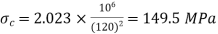
(iii) 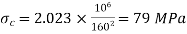
(iv) 
Both ends fixed

Q20) Two steel struts have the same cross-sectional areas. One is a solid one and the other is a hollow with internal diameter three-fourth of the external diameter. Compare the ratio of the strength of the solid steel strut to that of the hollow one.
A20)
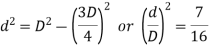
Ratio of diameters
As the areas of two struts are equal, 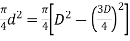
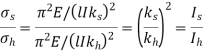
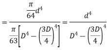
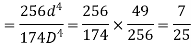
Ratio of strengths
As the cross-sectional areas of two struts are equal the ratio of their strengths depends upon critical stress values.
Q21) A uniform bar of steel is heated such that its temperature varies from 0.5 t at one end to t at the other. The bar is of uniform cross-sectional area A and flexural stiffness El. One end is pin-jointed to a rigid foundation and the other is pin-jointed so that the bar can slide along its axis, the thermal expansion of which is resisted by the compression of a spring of stiffness assuming that there is no load on the bar before heating, deduce an expression for the stress in the bar when it is heated. Also show that the bar buckles in flexure when
 where is the coefficient of linear thermal expansion.
A21)
Expression for stress
The average temperature along the bar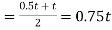
Thermal expansion of the bar=0.75lt
Let P be the force exerted by the spring on the bar on heating of the bar.
Compression of the bar under force 
Net expansion of bar=Compression of spring
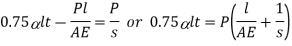

And stress in the bar, 
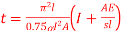
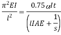
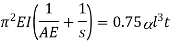
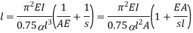
Buckling of bar
The bar will buckle when the load reaches to Euler’s value
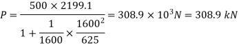
Q22) A 3.2 m long fixed end hollow cast iron column with ID as 60 mm & OD as 80 mm. Crushing stress = 500 Mpa & Rankine constant is 1/1600. Use Ranking crippling load.
A22)
Determination of 

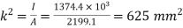 or
or 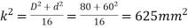
Rankine’s crippling load
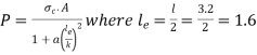 m for both ends fixed
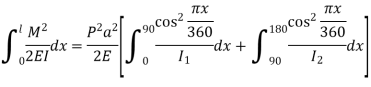
Q23) A 180 mm long steel strut is made up two lengths, one is 90mm long and 6 mm in diameter whereas the other is of the same length but is 8mm in diameter. It is rigidity fixed at the larger end and carries an axial load at the smaller end. Determine the magnitude of the crippling load. E for steel is 210 GPa.
A23)
Assuming the defected from under the action of the crippling load be
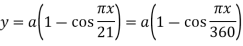
And thus, 
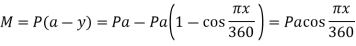
The crippling load is given by 
Numerator 
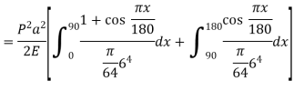
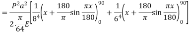
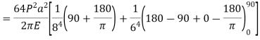

Denominator 
Crippling load