Unit - 5
Curved Beams & Unsymmetrical Bending
Q1) Derive equations for strain energy of Bars of small initial curvature.
A1)
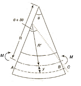
Strain in the element,


As, length of neutral axis remains constant,


As, curvature is very small and thus y is very small compared to R, thus can be neglected in denominator.

Normal stress,

As, total normal force is zero,

Neutral axis passes through the centroid,
Moment of resistance,


Strain energy of a small length  along the neutral axis under the bending moment M,

Q2) Derive the General equation for Winkler -Bach Theory.
A2)
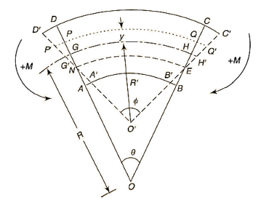
Assumptions:
- Limit of proportionality does not exceed.
- Plane transverse sections remain plane after bending.
- The material is isotropic and obeys Hooke's law.
- There are no radial strains.
- No buckling failure takes place.
Initial curvature = ABCD
Final curvature = 
Bending moment applied = M
GH = centroidal axis
PQ = any fiber at radial distance y
NE = Neutral axis
 = angles of small length at center of curvature before & after bending.


So,


The resisting moment about, an axis through the centroid,

Moments of total area about centroidal axis is zero,
i.e., 

Let,


Total force on cross-section  or
or  in circumferential direction,


As, transverse plane section sections before bending remain plain after bending, F =0

Dividing by, 

Now,


At the inside of the centroidal axis, y is negative

Position of neutral axis by 

 for different sections can be evaluated by following simplified expression.

Q3) Find the Position of neutral axis for rectangular cross-section.
A3)
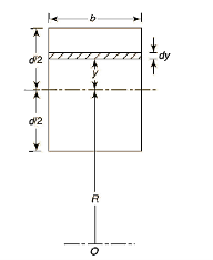
A = bd & dA = b*dy

Q4) Find the Position of neutral axis for Trapezoidal Cross-section.
A4)
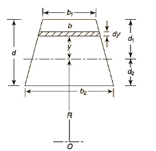


Adding & subtracting by,


In this equation,


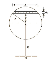
Q5) Find the Position of neutral axis for Circular cross-sectional.
A5)


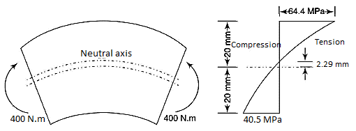
Q6) A curved bar of rectangular section of 30-mm width, 40-mm depth and mean radius of curvature of 60 mm is initially unstressed. If a bending moment of 400 Nm. Is applied to the bar which tends to straighten it, determine the stresses at the inner and outer surfaces and sketch a diagram to show the variation of stress across the section. Also find the position of the neutral axis.
A6)

Stress at outside face

Stress at inside face

Position of neutral axis,

Q7) A crane hook having a trapezoidal horizontal cross-section is 50 mm wide inside and 30 mm wide outside. Thickness of the section is 60 mm. The crane hook carries a vertical load of 20 kN whose line of action is 50 mm from the inside edge of the section. The centre of curvature is 60 mm from the inside edge. Determine the maximum tensile and compressive stresses in the section.
A7)
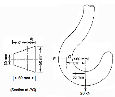


Calculating 


Stress at outside face (P)


Stress at inside face (Q)


Direct stress
Direct stress
Maximum stresses
At the outside edge 
At the inside edge 
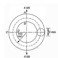
Q8) A ring of steel bar has a diameter of 20 mm and carries a pull of 4 kN as shown. Determine the stresses at points A, B, C and O of the rim. The mean radius of the rim is 100mm.
A8)
Calculating 


Stress at A
At A, 


Stress at B
At B,  , y is negative


Stress at C
At C, 


Stress at D
At D,  , y is negative


 (tensile)
Q9) A steel ring of 240 mm of mean diameter has a rectangular cross-section of 60 mm X 40 mm, the larger section being in the radial direction. Determine the tensile force which the ring can carry safely if the permissible stress is 140 MPa.
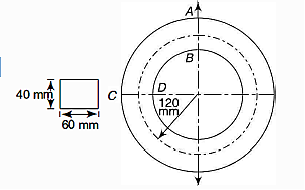
A9)
Calculating 

Calculating safe tensile force
The tensile stresses are developed at A and D
At A, 


At D, 


Thus the safe load is 90.517 kN
Q10) Write Properties of beam cross‐section
A10)
In addition to its material and other features, the strength of a structural component is determined by the geometrical properties of its cross-section. A beam with a large cross-section, for example, will be able to withstand a bending moment more readily than one with a smaller cross-section. A cross-section of a typical structural element is depicted.
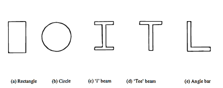
Centroid:
The position of the centroid of a cross-section is the center of the moment of area of the cross-section. If the cross-section is constructed from a homogeneous material, its centroid will lie at the same position as its center of gravity.
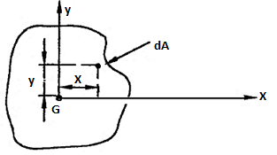
Let G denote the position of the centroid of the plane lamina. At the centroid the moment of area is zero, so that the following equations apply,

DA = elemental area of the lamina
x = horizontal distance of dA from G
y = Vertical distance of dA from G
Centroidal axes:
These are the axes that pass through the centroid.
Second moment of area (I):
The second moments of area of the lamina about the x - x and y - y axes, respectively, are given by,


From Pythagoras theorem,


Above equation is known as the perpendicular axes theorem which states that the sum of the second moments of area of two mutually perpendicular axes of a lamina is equal to the polar second moment of area about a point where these two axes cross.
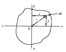
Where,
J = polar second moment of area

Parallel axes theorem:
Consider a lamina where the x-x axis passes through its centroid. Suppose that  , is known and that
  , is required, where the X-X axis lies parallel to the x-x axis and at a perpendicular distance h from it.
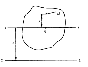


But,


This is known as the parallel axis’s theorem, which states that the second moment of area about the X-X axis is equal to the second moment of area about the x-x axis +  , where x-x and X-X are parallel.
h = the perpendicular distance between the x-x and X-X axes.
 = the second moment of area about x-x
 = the second moment of area about X-X
Section modulus:
The maximum bending stress in a beam is calculated as,

Where y is the distance from the neutral axis to the extreme fiber,  is the centroidal moment of inertia, and M is the bending moment.
The section modulus combines the y and  terms in the bending stress equation:

Using the section modulus, the bending stress is calculated as,

The utility of the section modulus is that it characterizes the bending resistance of a cross section in a single term. This allows for optimization of a beam's cross section to resist bending by maximizing a single parameter.
The ratio I/ y where y is the farthest or the most distant point of the section from the neutral axis is called section modulus. It is denoted by Z.
Q11) What is the section modulus (Z) for a rectangular section?
A11)
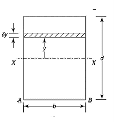

We know that the moment of inertia of the section about X-X axis,

Now moment of inertia of the whole section may be found out by integrating the above equation for the whole length of the lamina i.e., from  to
to  .
.


By, parallel axis theorem,

Section Modulus,

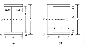
Q12) What is the section modulus (Z) for a I section?
A12)


Q13) What is the section modulus (Z) for a Circular section?
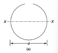
A13)


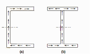
Q14) Determination of shear center and flexural axis for Channel Section.
A14)

Net force applied on elemental area  towards left,

Total force applied on gross area of block,

This force on the block tends to slide the block towards left which is resisted by the shear force due to, complimentary shear stress in vertical plane at QT.
Net shear force at the surface = shear stress * area

Equating the two forces,



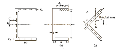
Moment of inertial,

Shear stress in elementary length,

Shear force in elementary length,

Total force in each flange,

Now, if the force F acts through the vertical axis of the web, no moments result from the vertical forces whereas clockwise moments give rise to a clockwise couple which can twist the cross-section of the channel. However, if the line of application of the vertical force F is displaced to the left at a distance e from the vertical axis of the web, the clockwise couple due to force in the flanges can be made to balance with the counter-clockwise couple to external force F and vertical force in the web,


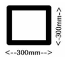
Q15) Find the modulus of section of square beam of size 300×300 mm.
A15)
Here, a = side of square section = 300 mm.
For square section,
I = a4/12. y= a/2.
Z = I/y = a3/6
= 3003/6
= 4.5 × 106 mm3.
Q16) A Steel rod 200 mm diameter is to be bent into a circular arc section. Find radius of curvature. Take f = 120N/mm2 & E = 2×10⁵ N/mm2.
A16)
Given:
Diameter of Steel rod = 200mm; y = d/2 = 100mm.
f= 120N/mm2.
E= 2×10⁵N/mm2.
By flexural equation we have f/y = E/R
R = 2×10⁵/ 120 ×100
= 166.6m.
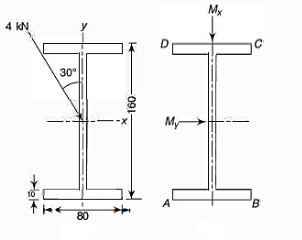
Q17) A simple supported beam carries a central load of 4 kN the load acts through the centroid, the line of action is inclined at 30° to the vertical direction. Determine the maximum stress.
A17)
Moment of inertia


Bending moments:
Maximum bending moment
 (to induce tensile stress in lower half)
 (to induce tensile stress in right half)
Bending stresses
x and y both are positive in the lower right half (4th) quadrant.
The maximum tensile stress occurs at B,

The maximum compressive stress occurs at D and is 59.34 MPa
Q18) Determine the stresses at 4 corners for figure shown.
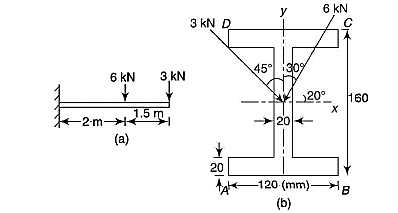
A18)
Moment of inertia 
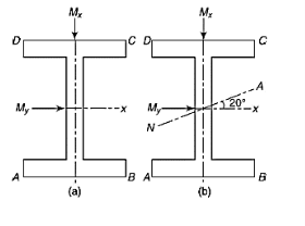


Bending moments
Remembering that it is a cantilever
 (to induce tensile stress in upper half
 (to induce tensile stress in upper half
Thus x and y both are positive in the upper left (2nd) quadrant.
Bending stresses
The maximum tensile stress occurs at D,
Now 
Neutral axis
Inclination of the neutral axis with x-axis given by


Q19) The cross-section of a 3 m long simply supported beam of T-section carrying a central load inclined at 30° to the y-axis. Determine the maximum load the beam can sustain if the maximum tensile and compressive stresses are not allowed to exceed 40 MPa and 80 MPa respectively. Locate the neutral axis also. The load passes through the centroid of the section.
A19)
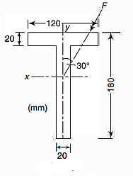
Moment of inertia as the section has y-axis as axis of symmetry. It is a principal axis. The other principal axis will be at a perpendicular through the centroid (Fig 5.53a)


Let F be the maximum load at the centre in kN.
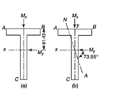
Bending moments
Maximum bending moment
 (to induce tensile stress in lower half)
 (to induce tensile stress in left half)
Thus x and y both are positive in the lower left (3rd ) quadrant).
Neutral axis
The equation for the neutral axis is  or
or 


Neutral axis will pass through 2nd and 4ht quadrant as shown in fig. 5,48 b
Bending stresses
The maximum tensile stress occurs at A or C, ie.


And 

Maximum compressive stress will be at B,


Thus the maximum load can be 7.229Kn
Q20) The cross-section of a cantilever channel beam that is 3 m in length. The beam supports a load of 2 kN inclined at 30° to the longitudinal plane at the free end. Locate the position of the neutral axis and find the maximum tensile stress acting on the built-in end. Assume the line of action of load to pass through the shear center.
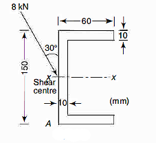
A20)
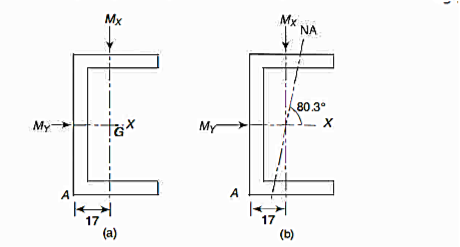
Moment of inertia

 can also be found as under:
 can also be found as under:


Bending moments
Maximum bending moment
Resolving into components
 (due to vertical component of load)
 (due to horizontal component of load)
As it is a cantilever, both of these components induce tensile stress in the upper left quadrant ie above x-axis and left of y-axis in the quadrant containing point A.
Position of neutral axis
The equation for the neutral axis is =0


Neutral axis passes through 2nd and 4th quadrant.
Maximum tensile stress
Maximum tensile stress at A=1.101×75+3.942 ×17=149.6 MPa
Q21) An angle beam of 300 mm X 300 mm size is loaded as shown in Fig. 5.58. Determine the direction of the neutral axis and the bending stresses at A, Band C. The line of action of the load passes through the shear center of the cross-section.
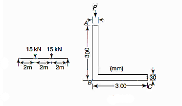
A21)
Moment of inertia about x and y-axis

As it is symmetric angle section,
 (fig 6=5.59)

Moment of Inertial about x-axis and y-axis

As it is symmetric angle section  (fig 5.59)

Due to symmetry 


Moment of inertial about principal axes
 can be found from eq 5.21


Principal axes
Inclination of principle u-axis


Or 

u and v-axis along with four quadrants with respect to these axes are shown in fig.
Bending moments
Maximum bending moment 
 (to induce tensile stress in 3rd and 4th quadrants)
 (to induce tensile stress in 1st and 4th quadrants)
Thus u and v both are positive in the 4th quadrant.
Bending stresses
For π, 

For A, 


 (compressive)
For C,  v negative; u positive.

Position of neutral axis
Inclination of the neutral axis, 

Neutral axis is shown in fig. b. As sngle is negaive, the neutral aixs has to pass through 1st and 3rd quadrants.