Unit - 3
Spur Gears
Q1) Explain tooth forms.
A1)
- Involute teeth profile:
An involute teeth profile is defined as the locus of a point on a straight line that rolls without slipping on the circumference of a circle. The circle on which the straight lines roll is known as the base circle.
Let A be the point on a base circle. First divide the circle into an equal number of parts, for example, Ap1=P1P2=P2P3, etc. Draw the tangents at points P1, P2, P3, etc. Cut the length equals to AP1, AP2, and AP3 on the tangents made from points P1, P2, and P3 and mark the points as A1, A2, and A3.
Join all the points, will form an involute teeth profile. For such teeth profile, normal at any point of an involute is a tangent to the base circle.
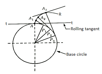
Fig. 1: Involute teeth
2. Cycloidal Teeth profile:
It is a locus of a point on the circumference of the circle that rolls without slipping on a fixed straight line. When a circle rolls without slipping on the circumference of another circle, the locus of a point on the circle is known as epicycloid. If a circle rolls without slipping inside the circumference of another circle, the locus of the point on the circle is known as hypocycloid.
Let APB is a circle inside which a circle H rolls. When rolling starts, A is the point of contact. As the circle rolls, the locus of point A gives a path ALP which is a hypocycloid. A small portion of the curve near the pitch circle is used for the flank of the tooth.
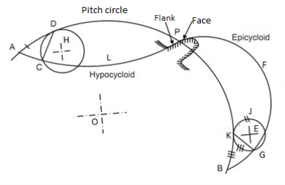
Fig. 2: Cycloidal tooth profile
Let a circle E rotates or rolls outside the pitch circle, then the locus of its point of contact form an epicycloids PFB. A small portion of the curve near the pitch circle is used for the face of the tooth.
Q2) Explain system of gear teeth.
A2)
- The following four systems of gear teeth are commonly used in practice:
- 14.50 composite system,
- 14.50 full depth involute system
- 200 full depth involute system, and
- 200 stub involute system
b. The 14.50 composite systems are used for general purpose gears. It is stronger but has no interchangeability. The tooth profile of this system has cycloidal curves at the top and bottom and involute curve at the middle portion.
c. The tooth profile of the 14.50 full depth involute system was developed for use with gear hobs for spur and helical gears.
d. The tooth profile of the 200 full depth involute systems may be cut by the hobs. The increase of the pressure angle from14.50 to 200 results in a stronger tooth because the tooth acting as a beam is wider at the base.
e. The 200 stub involute systems have a strong tooth to take heavy loads.
Q3) What is contact ratio?
A3)
Contact ratio
It is defined as the ratio of the length of the arc of contact to the circular pitch.
Contact ratio=Length of the arc of contact/p
Where p=circular pitch=πm
Q4) Explain standard proportions of gear systems.
A4)
S.No. | Particulars | 14(1/2)0 composite or full depth involute system(m) | 200full depth involute system(m) | 200 stub involute system(m) |
1. | Addendum | 1 | 1 | 0.8 |
2. | Dedendum | 1.25 | 1.25 | 1 |
3. | Working Depth | 2 | 2 | 1.60 |
4. | Minimum tooth depth | 2.25 | 2.25 | 1.80 |
5. | Tooth Thickness | 1.5708 | 1.5708 | 1.5708 |
6. | Minimum Clearance | 0.25 | 0.25 | 0.2 |
7. | Fillet radius at root | 0.4 | 0.4 | 0.4 |
Q5) What is interference in involute gears?
A5)
The phenomenon when the tip of a tooth undercuts the root on its mating gear is known as interference.
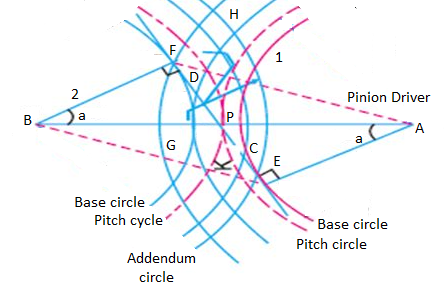
Fig. 3: Interference of gear
Q6) What is black lash?
A6)
Backlash
It is the difference between the tooth space and the tooth thickness as measured on the pitch circle. It is sometimes, a clearance or lost motion in a mechanism, which can be defined as the maximum angle or distance through which any part of the mechanical system moved in one direction without applying appreciable force to the next part of the mechanical system.
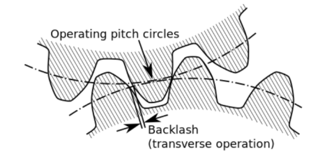
Fig. 4: Backlash
Q7) Explain gear manufacturing methods.
A7)
The gear manufacturing method can be classified into major two categories:
- Forming:
It is having various other techniques like direct casting, molding, extrusion of tooth form in molten or drawing, and powered or heat softened material.
2. Machining:
It is a very common and conventional method for gear manufacturing in which the roughing and other finishing operations are involved for manufacturing.
Characteristics of forming and machining method:
The accuracy of the tooth is entirely dependent on the quality of the die or the mold and in general, it is less than can be obtained from finishing methods or we can say than of machining operations.
Q8) What are the design considerations?
A8)
Following are the considerations met in the design of gear drive:
- The gear should have sufficient strength so that it will not fail under static load or dynamic loading during normal running conditions.
- The gear tooth should have to wear characteristics so that their life is satisfactory.
- The use of space and material should be economical.
- The alignments of the gear and the deflections of the shafts must be considered because they affect the performance of the gears.
- The lubrication of the gears must be satisfactory.
Q9) What is beam strength of gear tooth?
A9)
It is determined from an equation known as Lewis and the load-carrying ability of the toothed gear as determined by this equation gives satisfactory results.
Consider each tooth as a cantilever beam loaded by a normal load (WN)
It is resolved into two components that are tangential (WT) component and radial component (WR) acting perpendicular and parallel to the line of tooth respectively.
The tangential component (WT) induces bending stress which tends to break the tooth.
The radial component (WT) induces compressive stress of relatively small magnitude; therefore its effect on the tooth may be neglected. Hence, the bending stress is used as the basis for design calculations.
The critical or the section of maximum bending stress may be obtained by drawing a parabola through A and tangential to the tooth curves at B and C.
The tooth is larger than the parabola at every section except BC is the section of maximum stress or the critical section.
Let,
h=Length of the tooth
T= thickness of the tooth
b =width of the face
The maximum value of the bending stress at section BC is given by
σw =My/I, where, M= maximum bending moment
y=half of the thickness, I=moment of inertia about the center.
Substituting, the values for M, y, and I in the above equation, we get
σw=[(WT*h)t/2]/(bt3/12)
=(WT*h)6/bt2
Let,
t=xpc and h=kpcwhere x and k are constants
WT= σwb(x2pc2)/6kpc
The value of y in terms of the number of teeth may be expressed as follows:
y =0.124-(0.684/T), for 14.50 composite and full depth involute system.
= 0.154-(0.912/T), for 200 full depth involute system.
=0.175- (0.841/T), for 200 stub system.
Q10) What is dynamic tooth load?
A10)
The dynamic loads are due to the following reasons:
- Inaccuracies of tooth spacing.
- Irregularities in tooth profiles, and
- Deflections of the teeth under load.
Total dynamic load,
WD=WT+Wt
Where, WT= steady load due to transmitted torque, and
Wt= Increment load due to dynamic action
The increment load depends upon the pitch line velocity, the face width, material of the gear, and the accuracy of cut, and the tangential load.
For average conditions, the dynamic load is determined by using the following Buckingham equation,
WD=WT+21v(bc+WT)/(21v+ )
)
Where,
v= pitch line velocity
b= face width
C=A deformation or dynamic factor
Q11) What is Wear strength of gear tooth?
A11)
Wear strength for satisfactory wear is obtained by using the following Buckingham equation, equation
Ww=DpbQK
Where W= maximum limiting load for wear in Newton
Dp= Pitch circle diameter
b= face circle, Q=Ratio factor
=2VR/(VR+1)
=2TG/(TG+TP) (For external gears)
=2VR/(VR-1)
=2TG/(TG-TP) (For internal gears)
VR=Velocity ratio, K= Load stress factor
Q12) What are the failure of gear tooth?
A12)
The factors for failure of gear tooth are as follows:
- Pressure angle:
It is the angle at which the line of action makes with the common tangent to the pitch circle. It is also called the angle of obliquity. It is denoted by φ.
2. Breakage of the tooth due to static and dynamic load:
If the total repetitive load (sum of static and dynamic load) on the gear tooth is greater than the beam strength of the gear tooth, then the gear tooth will fail in bending.
3. Surface Destruction:
- Abrasive Wear:
The main cause of abrasive wear is dirt, rust, weld spatter, or metallic debris. This can be reduced by the provision of oil filters, increasing surface hardness, and the use of highly viscous oil.
b. Corrosion Wear:
The corrosion of the tooth surface is caused by corrosive elements, such as extreme pressure additives present in lubricating oil and foreign material due to external contamination. This can be reduced by the complete enclosure of the gear and selecting proper additives.
c. Pitting:
The cause of pitting is the errors in the tooth profile, surface irregularities, and misalignment of gears. It can be reduced by precise machining of gears.
d. Scoring:
The oil film between the gear teeth breaks down due to excessive surface pressure and high surface speed. This results in excessive frictional heat and overheating of the meshing teeth. This can be controlled by controlling the temperature within the permissible limit with the help of parameters like surface speed etc.
Q13) Explain design of spur gears
A13)
Step 1: Calculation of Tangential load, which is obtained from the power transmitted and the pitch line velocity by using the following relation:
WT=(P/v)CS
Where, WT=Tangential tooth load, P= power transmitted in watts, v=πDN/60= pitch line velocity, CS= service factor, N= speed in rpm, D= Pitch circle diameter.
Step 2: Apply Lewis equation: WT=σwbpcy=σwbπmy=(σ0Cv) bπmy
Equating two values of WT= obtained from step 1 and step 2, we get the value of the module. Other values may be obtained by using the standard tooth proportions for spur gears.
Step 3: Check for wear
Calculate the tooth load, Ww=DpbQK, ifWT<Ww, the design is safe.
For designing spur gear, the following formulae are quite important: WT=(P/v)CS,WT=(σ0Cv) bπmy and Ww=DpbQK,
Q14) Explain various terminology used in helical gears?
A14)
Helix angle: It is defined as the angle between the axis of the shaft and the centerline of the tooth taken on the pitch plane.
Transverse circular pitch (p)
The distance A1A2 in figure 2.2 is called the transverse circular pitch (p), which is measured in the plane of rotation.
Normal circular pitch (pn) The distance AC1 in figure 2.2 is called the normal circular pitch (pn), which is measured in a plane perpendicular to the tooth elements.
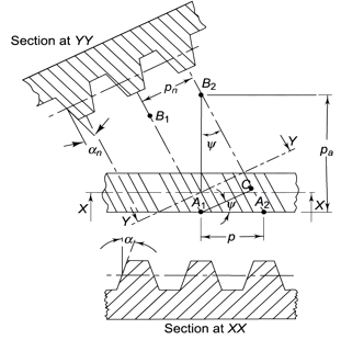
Figure 5. Tooth Relationships


From the above expression, We get

Where Pn and P are normal and transverse diametral pitches respectively.
UsingP=1/m, we get
We get,
Where,
mn = normal module (mm)
m = transverse module (mm)
Axial pitch (pa) In figure 2.2in triangle A1A2B2 the distance A1B2 represents the axial pitch, which is given by the following formula.

Transverse pressure angle (α) Pressure angle in the transverse plane is known as the transverse pressure angle.
Normal-pressure angle (αn) Pressure angle in the normal plane is known as the normal pressure angle.
The relation between transverse and normal pressure angle is given by the following equation.

Pitch circle diameter (d) Pitch circle diameter of helical gear is calculated by the following relation,

Where z= number of teeth on the gear.
Central distance (a) The center to center distance a between the two helical gears having zl and z2 as the number of teeth is given by,

Q15) Explain beam strength and wear strength of helical gears.
A15)
Beam Strength of Helical Gear
To determine beam strength, the helical gear is considered to be equivalent to a formative spur gear, the beam strength of this formative spur gear is given by

Where,
( Sb)n=beam strength perpendicular to the tooth element,
mn = normal module
 = face width along with the tooth element
σb= bending stress on gear tooth
Y= Lewis Form factor based on virtual number of teeth
Using the relation, 
We get 
The above equation gives the beam strength of the helical gear. It is the maximum value of the tangential force that the tooth can transmit without bending failure.
Effective load on Gear Tooth
Tangential force on the helical gear tooth is given in table 2.1, which depends upon the rated power and rated speed. But during the operation, a dynamic load also acts on the gear tooth which can be considered on the following two basis-
(i) Based on the velocity factor this method of load estimation is used in the preliminary stages of gear design. The effective load in this stage is given by

Where,
Cs = service factor
Cv = velocity factor, for helical gear velocity factor, is given by the following relation

v= velocity in m/sec
(ii) Buckingham equation In the final stages of gear design, when gear dimensions are known, errors specified and the quality of gears determined, the dynamic load is calculated by an equation derived by Earle Buckingham and given by the following equation

Where Pd= incremental dynamic load, given by

v = pitch line velocity (m/s)
C = deformation factor (N/mm2)
e = sum of errors between two meshing teeth (mm)
b = face width of tooth (mm)
Pt = tangential force due to rated torque (N)
Deformation factor C is given by

Where,
k = constant depending upon the form of tooth
Ep = modulus of elasticity of pinion material (N/mm2 )
Eg = modulus of elasticity of gear material (N/mm2 )
Q16) Explain Wear strength of helical gears.
A16)
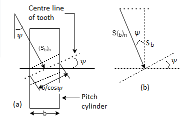
The wear strength equation of the spur gear is modified to suit helical gears. For this purpose, a pair of helical gears is considered to be equivalent to a formative pinion and a formative gear in a plane perpendicular to the tooth element. In the case of spur gears wear strength is given by

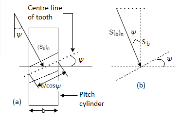
Referring to Fig.
Sw = (Sw)n = wear strength perpendicular to the tooth element
 = face width along with the tooth element
 = pitch circle diameter of the formative pinion.
Using above relations we get

The component of (Sw)n in the plane of rotation is denoted by Sw. Therefore,

Which gives,

Where
Q= ratio factor, given by

Zp= actual number of teeth on the pinion
Zg= actual number of teeth on the gear
K= Load stress factor, given by

σc = surface endurance strength (N/mm2)
Ep, Eg = moduli of elasticity of materials for pinion and gear (N/mm2)
To design the gear

Or 
Where, fs= factor of safety
Unit - 3
Unit - 3
Spur Gears
Q1) Explain tooth forms.
A1)
- Involute teeth profile:
An involute teeth profile is defined as the locus of a point on a straight line that rolls without slipping on the circumference of a circle. The circle on which the straight lines roll is known as the base circle.
Let A be the point on a base circle. First divide the circle into an equal number of parts, for example, Ap1=P1P2=P2P3, etc. Draw the tangents at points P1, P2, P3, etc. Cut the length equals to AP1, AP2, and AP3 on the tangents made from points P1, P2, and P3 and mark the points as A1, A2, and A3.
Join all the points, will form an involute teeth profile. For such teeth profile, normal at any point of an involute is a tangent to the base circle.
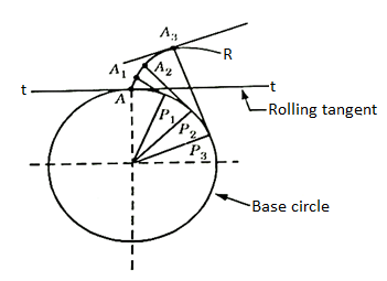
Fig. 1: Involute teeth
2. Cycloidal Teeth profile:
It is a locus of a point on the circumference of the circle that rolls without slipping on a fixed straight line. When a circle rolls without slipping on the circumference of another circle, the locus of a point on the circle is known as epicycloid. If a circle rolls without slipping inside the circumference of another circle, the locus of the point on the circle is known as hypocycloid.
Let APB is a circle inside which a circle H rolls. When rolling starts, A is the point of contact. As the circle rolls, the locus of point A gives a path ALP which is a hypocycloid. A small portion of the curve near the pitch circle is used for the flank of the tooth.
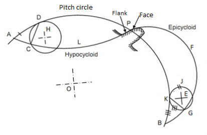
Fig. 2: Cycloidal tooth profile
Let a circle E rotates or rolls outside the pitch circle, then the locus of its point of contact form an epicycloids PFB. A small portion of the curve near the pitch circle is used for the face of the tooth.
Q2) Explain system of gear teeth.
A2)
- The following four systems of gear teeth are commonly used in practice:
- 14.50 composite system,
- 14.50 full depth involute system
- 200 full depth involute system, and
- 200 stub involute system
b. The 14.50 composite systems are used for general purpose gears. It is stronger but has no interchangeability. The tooth profile of this system has cycloidal curves at the top and bottom and involute curve at the middle portion.
c. The tooth profile of the 14.50 full depth involute system was developed for use with gear hobs for spur and helical gears.
d. The tooth profile of the 200 full depth involute systems may be cut by the hobs. The increase of the pressure angle from14.50 to 200 results in a stronger tooth because the tooth acting as a beam is wider at the base.
e. The 200 stub involute systems have a strong tooth to take heavy loads.
Q3) What is contact ratio?
A3)
Contact ratio
It is defined as the ratio of the length of the arc of contact to the circular pitch.
Contact ratio=Length of the arc of contact/p
Where p=circular pitch=πm
Q4) Explain standard proportions of gear systems.
A4)
S.No. | Particulars | 14(1/2)0 composite or full depth involute system(m) | 200full depth involute system(m) | 200 stub involute system(m) |
1. | Addendum | 1 | 1 | 0.8 |
2. | Dedendum | 1.25 | 1.25 | 1 |
3. | Working Depth | 2 | 2 | 1.60 |
4. | Minimum tooth depth | 2.25 | 2.25 | 1.80 |
5. | Tooth Thickness | 1.5708 | 1.5708 | 1.5708 |
6. | Minimum Clearance | 0.25 | 0.25 | 0.2 |
7. | Fillet radius at root | 0.4 | 0.4 | 0.4 |
Q5) What is interference in involute gears?
A5)
The phenomenon when the tip of a tooth undercuts the root on its mating gear is known as interference.
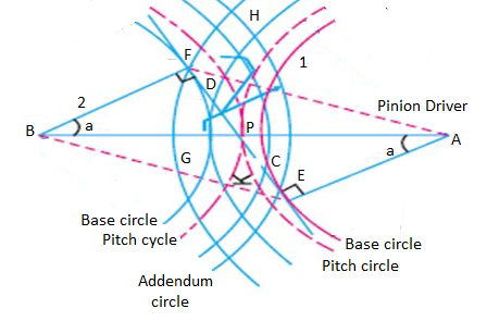
Fig. 3: Interference of gear
Q6) What is black lash?
A6)
Backlash
It is the difference between the tooth space and the tooth thickness as measured on the pitch circle. It is sometimes, a clearance or lost motion in a mechanism, which can be defined as the maximum angle or distance through which any part of the mechanical system moved in one direction without applying appreciable force to the next part of the mechanical system.
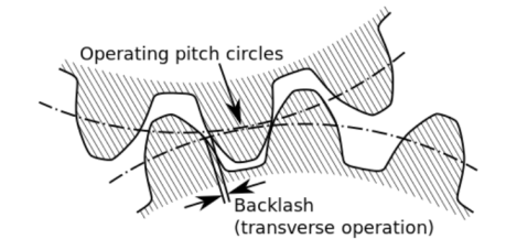
Fig. 4: Backlash
Q7) Explain gear manufacturing methods.
A7)
The gear manufacturing method can be classified into major two categories:
- Forming:
It is having various other techniques like direct casting, molding, extrusion of tooth form in molten or drawing, and powered or heat softened material.
2. Machining:
It is a very common and conventional method for gear manufacturing in which the roughing and other finishing operations are involved for manufacturing.
Characteristics of forming and machining method:
The accuracy of the tooth is entirely dependent on the quality of the die or the mold and in general, it is less than can be obtained from finishing methods or we can say than of machining operations.
Q8) What are the design considerations?
A8)
Following are the considerations met in the design of gear drive:
- The gear should have sufficient strength so that it will not fail under static load or dynamic loading during normal running conditions.
- The gear tooth should have to wear characteristics so that their life is satisfactory.
- The use of space and material should be economical.
- The alignments of the gear and the deflections of the shafts must be considered because they affect the performance of the gears.
- The lubrication of the gears must be satisfactory.
Q9) What is beam strength of gear tooth?
A9)
It is determined from an equation known as Lewis and the load-carrying ability of the toothed gear as determined by this equation gives satisfactory results.
Consider each tooth as a cantilever beam loaded by a normal load (WN)
It is resolved into two components that are tangential (WT) component and radial component (WR) acting perpendicular and parallel to the line of tooth respectively.
The tangential component (WT) induces bending stress which tends to break the tooth.
The radial component (WT) induces compressive stress of relatively small magnitude; therefore its effect on the tooth may be neglected. Hence, the bending stress is used as the basis for design calculations.
The critical or the section of maximum bending stress may be obtained by drawing a parabola through A and tangential to the tooth curves at B and C.
The tooth is larger than the parabola at every section except BC is the section of maximum stress or the critical section.
Let,
h=Length of the tooth
T= thickness of the tooth
b =width of the face
The maximum value of the bending stress at section BC is given by
σw =My/I, where, M= maximum bending moment
y=half of the thickness, I=moment of inertia about the center.
Substituting, the values for M, y, and I in the above equation, we get
σw=[(WT*h)t/2]/(bt3/12)
=(WT*h)6/bt2
Let,
t=xpc and h=kpcwhere x and k are constants
WT= σwb(x2pc2)/6kpc
The value of y in terms of the number of teeth may be expressed as follows:
y =0.124-(0.684/T), for 14.50 composite and full depth involute system.
= 0.154-(0.912/T), for 200 full depth involute system.
=0.175- (0.841/T), for 200 stub system.
Q10) What is dynamic tooth load?
A10)
The dynamic loads are due to the following reasons:
- Inaccuracies of tooth spacing.
- Irregularities in tooth profiles, and
- Deflections of the teeth under load.
Total dynamic load,
WD=WT+Wt
Where, WT= steady load due to transmitted torque, and
Wt= Increment load due to dynamic action
The increment load depends upon the pitch line velocity, the face width, material of the gear, and the accuracy of cut, and the tangential load.
For average conditions, the dynamic load is determined by using the following Buckingham equation,
WD=WT+21v(bc+WT)/(21v+ )
)
Where,
v= pitch line velocity
b= face width
C=A deformation or dynamic factor
Q11) What is Wear strength of gear tooth?
A11)
Wear strength for satisfactory wear is obtained by using the following Buckingham equation, equation
Ww=DpbQK
Where W= maximum limiting load for wear in Newton
Dp= Pitch circle diameter
b= face circle, Q=Ratio factor
=2VR/(VR+1)
=2TG/(TG+TP) (For external gears)
=2VR/(VR-1)
=2TG/(TG-TP) (For internal gears)
VR=Velocity ratio, K= Load stress factor
Q12) What are the failure of gear tooth?
A12)
The factors for failure of gear tooth are as follows:
- Pressure angle:
It is the angle at which the line of action makes with the common tangent to the pitch circle. It is also called the angle of obliquity. It is denoted by φ.
2. Breakage of the tooth due to static and dynamic load:
If the total repetitive load (sum of static and dynamic load) on the gear tooth is greater than the beam strength of the gear tooth, then the gear tooth will fail in bending.
3. Surface Destruction:
- Abrasive Wear:
The main cause of abrasive wear is dirt, rust, weld spatter, or metallic debris. This can be reduced by the provision of oil filters, increasing surface hardness, and the use of highly viscous oil.
b. Corrosion Wear:
The corrosion of the tooth surface is caused by corrosive elements, such as extreme pressure additives present in lubricating oil and foreign material due to external contamination. This can be reduced by the complete enclosure of the gear and selecting proper additives.
c. Pitting:
The cause of pitting is the errors in the tooth profile, surface irregularities, and misalignment of gears. It can be reduced by precise machining of gears.
d. Scoring:
The oil film between the gear teeth breaks down due to excessive surface pressure and high surface speed. This results in excessive frictional heat and overheating of the meshing teeth. This can be controlled by controlling the temperature within the permissible limit with the help of parameters like surface speed etc.
Q13) Explain design of spur gears
A13)
Step 1: Calculation of Tangential load, which is obtained from the power transmitted and the pitch line velocity by using the following relation:
WT=(P/v)CS
Where, WT=Tangential tooth load, P= power transmitted in watts, v=πDN/60= pitch line velocity, CS= service factor, N= speed in rpm, D= Pitch circle diameter.
Step 2: Apply Lewis equation: WT=σwbpcy=σwbπmy=(σ0Cv) bπmy
Equating two values of WT= obtained from step 1 and step 2, we get the value of the module. Other values may be obtained by using the standard tooth proportions for spur gears.
Step 3: Check for wear
Calculate the tooth load, Ww=DpbQK, ifWT<Ww, the design is safe.
For designing spur gear, the following formulae are quite important: WT=(P/v)CS,WT=(σ0Cv) bπmy and Ww=DpbQK,
Q14) Explain various terminology used in helical gears?
A14)
Helix angle: It is defined as the angle between the axis of the shaft and the centerline of the tooth taken on the pitch plane.
Transverse circular pitch (p)
The distance A1A2 in figure 2.2 is called the transverse circular pitch (p), which is measured in the plane of rotation.
Normal circular pitch (pn) The distance AC1 in figure 2.2 is called the normal circular pitch (pn), which is measured in a plane perpendicular to the tooth elements.
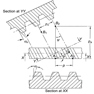
Figure 5. Tooth Relationships


From the above expression, We get

Where Pn and P are normal and transverse diametral pitches respectively.
UsingP=1/m, we get
We get,
Where,
mn = normal module (mm)
m = transverse module (mm)
Axial pitch (pa) In figure 2.2in triangle A1A2B2 the distance A1B2 represents the axial pitch, which is given by the following formula.

Transverse pressure angle (α) Pressure angle in the transverse plane is known as the transverse pressure angle.
Normal-pressure angle (αn) Pressure angle in the normal plane is known as the normal pressure angle.
The relation between transverse and normal pressure angle is given by the following equation.

Pitch circle diameter (d) Pitch circle diameter of helical gear is calculated by the following relation,

Where z= number of teeth on the gear.
Central distance (a) The center to center distance a between the two helical gears having zl and z2 as the number of teeth is given by,

Q15) Explain beam strength and wear strength of helical gears.
A15)
Beam Strength of Helical Gear
To determine beam strength, the helical gear is considered to be equivalent to a formative spur gear, the beam strength of this formative spur gear is given by

Where,
( Sb)n=beam strength perpendicular to the tooth element,
mn = normal module
 = face width along with the tooth element
σb= bending stress on gear tooth
Y= Lewis Form factor based on virtual number of teeth
Using the relation, 
We get 
The above equation gives the beam strength of the helical gear. It is the maximum value of the tangential force that the tooth can transmit without bending failure.
Effective load on Gear Tooth
Tangential force on the helical gear tooth is given in table 2.1, which depends upon the rated power and rated speed. But during the operation, a dynamic load also acts on the gear tooth which can be considered on the following two basis-
(i) Based on the velocity factor this method of load estimation is used in the preliminary stages of gear design. The effective load in this stage is given by

Where,
Cs = service factor
Cv = velocity factor, for helical gear velocity factor, is given by the following relation

v= velocity in m/sec
(ii) Buckingham equation In the final stages of gear design, when gear dimensions are known, errors specified and the quality of gears determined, the dynamic load is calculated by an equation derived by Earle Buckingham and given by the following equation

Where Pd= incremental dynamic load, given by

v = pitch line velocity (m/s)
C = deformation factor (N/mm2)
e = sum of errors between two meshing teeth (mm)
b = face width of tooth (mm)
Pt = tangential force due to rated torque (N)
Deformation factor C is given by

Where,
k = constant depending upon the form of tooth
Ep = modulus of elasticity of pinion material (N/mm2 )
Eg = modulus of elasticity of gear material (N/mm2 )
Q16) Explain Wear strength of helical gears.
A16)
The wear strength equation of the spur gear is modified to suit helical gears. For this purpose, a pair of helical gears is considered to be equivalent to a formative pinion and a formative gear in a plane perpendicular to the tooth element. In the case of spur gears wear strength is given by

Referring to Fig.
Sw = (Sw)n = wear strength perpendicular to the tooth element
 = face width along with the tooth element
 = pitch circle diameter of the formative pinion.
Using above relations we get

The component of (Sw)n in the plane of rotation is denoted by Sw. Therefore,

Which gives,

Where
Q= ratio factor, given by

Zp= actual number of teeth on the pinion
Zg= actual number of teeth on the gear
K= Load stress factor, given by

σc = surface endurance strength (N/mm2)
Ep, Eg = moduli of elasticity of materials for pinion and gear (N/mm2)
To design the gear

Or 
Where, fs= factor of safety