Unit - 4
Sliding Contract Bearing
Q1) Explain Sliding Contact Bearing Types in detail.
A1)
Sliding contact bearings are classified in three ways.
A. Based on type of load carried
B. Based on type of lubrication
C. Based on lubrication mechanism
A. Bearing classification based on type of load carried
(a). Radial bearings: These bearings carry only radial loads i.e. loads perpendicular to the axis of shaft
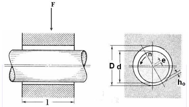
Fig. 1 Radial bearings
(b). Thrust bearings or axial bearings: These bearings carry only axial loads.
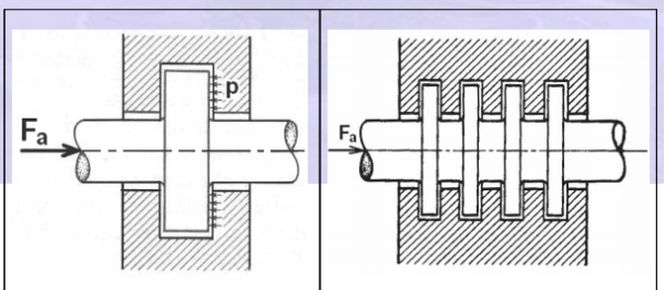
Fig.2(a) Single collar thrust bearing Fig. 2(b) Multiple collar thrust bearing
(c). Radial thrust bearings: These bearings carry both radial and thrust loads.
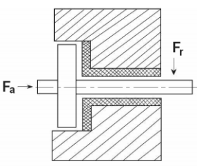
Fig. 3 Radial thrust bearing
B. Bearing classification based on type of Lubrication.
The type of lubrication means the extent to which the contacting surfaces are separated in a shaft bearing combination. This classification includes
(a) Thick film lubrication
(b) Thin film lubrication
(c) Boundary lubrication
(a). Thick film lubrication: As in Fig. (a) the surfaces are separated by thick film of lubricant and there will not be any metal-to-metal contact. The film thickness is anywhere from 8 to 20 μm. Typical values of coefficient of friction are 0.002 to 0.010. Hydrodynamic lubrication is coming under this category. Wear is the minimum in this case.
(b). Thin film lubrication: Here even though the surfaces are separated by thin film of lubricant, at some high spots Metal-to-metal contact does exist, Fig. 4 (b).Because of this intermittent contacts, it also known as mixed film lubrication. Surface wear is mild. The coefficient of friction commonly ranges from 0.004 to 0.10.

Fig. 4(a). Thick film lubrication (b) Thin film lubrication (c) Boundary lubrication
(c). Boundary lubrication: Here the surface contact is continuous and extensive as Shown in Fig (c). The lubricant is continuously smeared over the surfaces and provides a continuously renewed adsorbed surface film which reduces the friction and wear. The typical coefficient of friction is 0.05 to 0.20.
C. Bearing classification based on lubrication mechanism
(a). Hydrodynamic lubricated bearings: In these bearings the load-carrying surfaces are separated by a stable thick film of lubricant that prevents the metal-to-metal contact. The film pressure generated by the moving surfaces that force the lubricant through a wedge shaped zone. At sufficiently high speed the pressure developed around the journal sustains the load. This is illustrated in Fig 5.
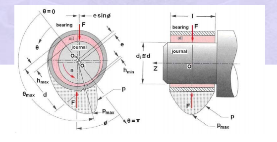
Fig. 5 Hydrodynamic lubricated bearings
(b). Hydrostatic lubricated bearings: In these bearings, externally pressurized lubricant is fed into the bearings to separate the surfaces with thick film of lubricant. These types of bearings do not require the motion of the surfaces to generate the lubricant film. Hence they can operate from very low speed to high speed. This is illustrated in Fig. 6
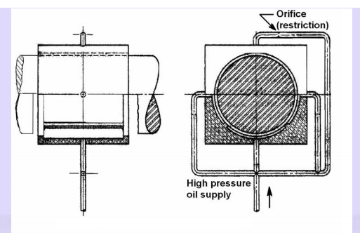
Fig. 6 Hydrostatic lubricated bearings
(c). Elastic hydrodynamic lubricated bearings: Rolling contact bearings come under this category. The oil film thickness is very small. The contact pressures are going to be very high. Hence to prevent the metal-to-metal contact, surface finishes are to be of high quality. Such a type of lubrication can be seen in gears, rolling contact bearings, cams etc.
(d). Boundary lubricated bearings: When the speed of the bearing is inadequate, less quantity of lubricant is delivered to the bearing, an increase in the bearing load, or an increase in the lubricant temperature resulting in drop in viscosity – any one of these may prevent the formation of thick film lubrication and establish continuous metal-to-metal contact extensively. Often bearings operating in such situations are called boundary lubricated bearings.
(e). Solid film lubricated bearings: For extreme temperature operations ordinary mineral oils are not satisfactory. Solid film lubricants such as graphite, molybdenum disulfide or their combinations which withstand high operating temperature are used. These types of bearings are common in furnace applications, hot drawing mills etc.
Q2) What is plain journal bearing?
A2)
The sliding contact bearing in which the sliding action is along the circumference of a circle and carrying radial loads are known as Plain Journal bearing or sleeve bearing.
Classification of Journal bearing:
The classifications of Plain journal bearing are mentioned below:
- Full journal bearing: In this bearing, the bearing completely covers the journal that is the angle of contact between the bearing and journal is 3600.
2. Partial Journal bearing: When the angle of contact between the bearing and journal is 1200. It is known as a journal bearing.
3. Fitted Journal Bearing: In this bearing, the contact angle is also1200 but there is no clearance between the bearings and the journal that is the diameter of bearing and journal are equal.
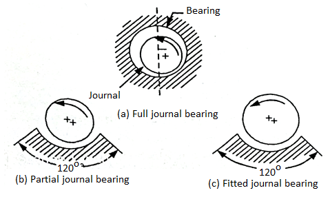
Fig. 7: Full, partial, fitted journal bearing
Q3) What is hydrodynamic lubrication?
A3)
Thick film lubrication is further divided into two groups: Hydrodynamic and Hydrostatic lubrication.
Hydrodynamic lubrication is defined as a system of lubrication in which the load-supporting fluid film is created by the shape and relative motion of the sliding surfaces.
Theory of Hydrodynamic Lubrication & Pressure Development in oil film:
The principle of hydrodynamic lubrication in journal bearings is shown in Fig. Initially, the shaft is at rest (a) and it sinks to the bottom of the clearance space under the action of load W. The surfaces of the journal and bearing touch during ‘rest’.
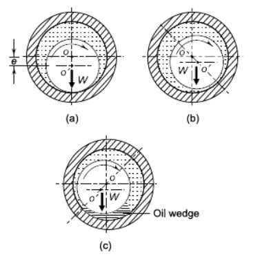
Fig.8 Hydrodynamic Lubrication (a) Journal at Rest (b) Journal Starts to Rotate (c) Journal at Full Speed
As the journal starts to rotate, it climbs the bearing surface (b) and as the speed is further increased, it forces the fluid into the wedge-shaped region (c). Since more and more fluid is forced into the wedge-shaped clearance space, pressure is generated within the system.
The pressure distribution around the periphery of the journal is shown in Fig. 16.2. Since the pressure is created within the system due to rotation of the shaft, this type of bearing is known as self-acting bearing. The pressure generated in the clearance space supports the external load (W). In this case, it is not necessary to supply the lubricant under pressure and the only requirement is sufficient and continuous supply of the lubricant. This mode of lubrication is seen in bearings mounted on engines and centrifugal pumps. Frequently, a term ‘journal’ bearing is used. A journal bearing is a sliding contact bearing working on hydrodynamic lubrication and which supports the load in radial direction. The portion of the shaft inside the bearing is called journal and hence the name ‘journal’ bearing.
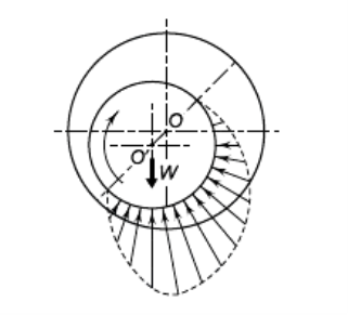
Fig. 9 Pressure Distribution in Hydrodynamic Bearing
Q4) Explain 2D Basic Reynolds Equation.
A4)
The theory of hydrodynamic lubrication is based on a differential equation derived by Osborne Reynold. This equation is based on the following assumptions:
(i) The lubricant obeys Newton’s law of viscosity.
(ii) The lubricant is incompressible.
(iii) The inertia forces in the oil fi lm are negligible.
(iv) The viscosity of the lubricant is constant.
(v) The effect of curvature of the fi lm with respect to film thickness is neglected. It is assumed that the fi lm is so thin that the pressure is constant across the fi lm thickness.
(vi) The shaft and the bearing are rigid.
(vii) There is a continuous supply of lubricant.
Fig. Shows a journal rotating in the clockwise direction supported by a film of lubricant of variable thickness h on a partial bearing, which is fixed. We specify that the journal has a constant surface velocity U. Using Reynolds’ assumption that curvature can be neglected, we fix a right-handed xyz reference system to the stationary bearing. We now select an element of lubricant in the film (Fig.a) of dimensions dx, dy, and dz, and compute the forces that act on the sides of this element.
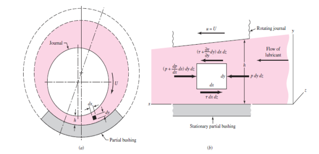
Fig. 10 An element of lubricant in the film
As shown in Fig, normal forces, due to the pressure, act upon the right and left sides of the element, and shear forces, due to the viscosity and to the velocity, act upon the top and bottom sides. Summing the forces in the x direction gives.

This reduces to

Also, we have

Where the partial derivative is used because the velocity u depends upon both x and y. Substituting Eq. (c) in Eq. (b), we obtain

Holding x constant, we now integrate this expression twice with respect to y. This gives


Note that the act of holding x constant means that C1 and C2 can be functions of x. We now assume that there is no slip between the lubricant and the boundary surfaces. This gives two sets of boundary conditions for evaluating the constants C1 and C2:
At y=0, u=0
At y=h, u=U
Notice, in the second condition, that h is a function of x. Substituting these conditions in Eq. (e) and solving for the constants gives


This equation gives the velocity distribution of the lubricant in the film as a function of the coordinate y and the pressure gradient dp/dx. The equation shows that the velocity distribution across the film (from y = 0 to y = h) is obtained by superposing a parabolic distribution onto a linear distribution.
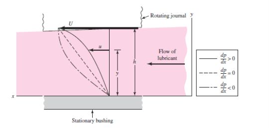
Fig 11. Velocity of the lubricant
Figure shows the superposition of these distributions to obtain the velocity for particular values of x and dp/dx. In general, the parabolic term may be additive or subtractive to the linear term, depending upon the sign of the pressure gradient. When the pressure is maximum, dp/dx = 0 and the velocity is

Which is a linear relation.
We next define Q as the volume of lubricant flowing in the x direction per unit time. By using a width of unity in the z direction, the volume may be obtained by the expression
Q =  (h)
(h)
Substituting the value of u from Eq. (6.1) and integrating gives

The next step uses the assumption of an incompressible lubricant and states that the flow is the same for any cross section. Thus

From equation (i)


Which is the classical Reynolds equation for one-dimensional flow. It neglects side leakage, that is, flow in the z direction. A similar development is used when side leakage is not neglected. The resulting equation is

There is no general analytical solution to Eq. (6.3); approximate solutions have been obtained by using electrical analogies, mathematical summations, relaxation methods, and numerical and graphical methods. One of the important solutions is due to Somerfield and may be expressed in the form

Where φ indicates a functional relationship. Somerfield found the functions for half-bearings and full bearings by using the assumption of no side leakage.
Q5) Explain Raimondi and Boyd method &Somerfield number
A5)
There is no exact solution to Reynold’s equation for a journal bearing having a finite length. However, AA Raimondi and John Boyd of Westinghouse Research Laboratory solved this equation on computer using the iteration technique. The results of this work are available in the form of charts and tables.
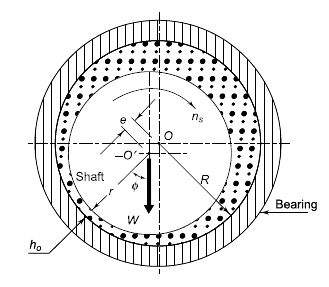
Fig 12
In Fig, O and O’ are the axes of bearing and journal respectively. The distance OO’ is called eccentricity and denoted by the letter ℇ. The radial clearance c is given by,
c=R-r
Where
c = radial clearance (mm)
R = radius of bearing (mm)
r = radius of journal (mm)
The eccentricity ratio ( ) is defined as the ratio of eccentricity to radial clearance.
Therefore

From Fig.
R=e+r+ho
Where,
ho = minimum fi lm thickness (mm)
Thus equation 6.5 became

The Somerfield number is given by

Where
S = Somerfield number (dimensionless)
u = viscosity of the lubricant (N-s/mm2) or (MPa-s)
ns = journal speed (rev./s)
p = unit bearing pressure, i.e., load per unit of the projected area (N/mm2)
The Somerfield number contains all variables, which are controlled by the designer.
Q6) What are thermal considerations?
A6)
Heat is generated in the bearing due to viscosity of the lubricating oil. The frictional work is converted into heat, which increases the temperature of the lubricant. Assuming that the total heat generated in the bearing is carried away by the total oil flow in the bearing, the expression for temperature rise can be determined. From Eq. (6.7),
(kW)f = (2πns)(fWr)(10-6)
Where
f = coefficient of friction =  CFV
CFV
CFV = coefficient of friction variable
W = 2plr,
p = unit bearing pressure
r = radius of journal (mm)
l = length of bearing (mm)
The heat generated (Hg) is given by,
Hg = (kW)f = (2πns)(fWr)(10-6)
Which reduces to
Hg = (4π)(10-6) rcns lp (CFV)
The heat carried away by oil flow (Hc) is given by,
Hc = m Cp Δt
Where,
m = mass of the lubricating oil passing throughthe bearing (kg/s)
Cp = specifi c heat of lubricating oil (kJ/kgºC)
∆t = temperature rise (°C)
The mass of the lubricating oil is given by,
m = ρQ (10-6) kg/s
Substituting
Q = rcns/(FV)
The mass is given by
m = ρ(rcnsl)(FV) (10-6) kg/s
Substituting the value of m in Hc
Hc = Cp Δt ρ(rcnsl) (FV)(10-6)
Equating the expressions for Hg and Hc,

For most lubricating oils,
ρ = 0.86 and Cp = 1.76 kJ/kgoC
Substituting these values in Eq. (16.22),

The average temperature of the lubricating oil is given by
Tav = Ti + 
Where Ti is the inlet temperature.
Q7) What are the parameters of bearing design?
A7)
In the preliminary stages of journal bearing design, it is required to select suitable values for the following parameters:
(i) length-to-diameter ratio
(ii) Unit bearing pressure
(iii) Radial clearance
(iv) Minimum oil film thickness
(i) Length to Diameter Ratio: In the design of hydrodynamic bearings, the diameter of the shaft is determined by strength or rigidity considerations and not on the basis of bearing capacity. Therefore, it is the bearing length that the designer has to decide to obtain a given bearing capacity. The length to diameter ratio (l/d) affects the performance of the bearing. As the ratio increases, the resulting film pressure increases as shown in Fig.
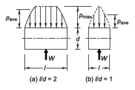
Fig. 13 Effect of (l/d) ratio on Average Bearing Pressure
A long bearing, therefore, has more load carrying capacity compared with a short bearing. A short bearing, on the other hand, has greater side flow, which improves heat dissipation. Therefore, the design trend is to use (l/d) ratio as 1 or less than 1. When the shaft and the bearing are precisely aligned, the shaft deflection is within the limit and cooling of lubricant and bearing does not present a serious problem, the (l/d) ratio can be taken as more than 1. In practice, the (l/d) ratio varies from 0.5 to 2.0, but in the majority of applications, it is taken as 1 or less than 1.
(ii) Unit Bearing Pressure: The unit bearing pressure is the load per unit of projected area of the bearing in running condition. It depends upon a number of factors, such as bearing material, operating temperature, the nature and frequency of load and service conditions. The values of unit bearing pressure, based on past experience, are given in Table.
Table: Permissible bearing pressures
S.No. | Application | Unit bearing pressure (p) (N/mm2) |
1 | Diesel engines Main bearing Crank pin Gudgeon pin |
5-10 7-14 13-14 |
2 | Automotive engines Main bearing Crank pin |
3–4 10–14 |
3 | Air compressors Main bearing Crank pin |
1–1.5 1.5–3.0 |
4 | Centrifugal pumps Main bearing |
0.5–0.7 |
5 | Electric motors Main bearing |
0.7–1.5 |
6 | Transmission shafting Light duty Heavy duty |
0.15 1.00 |
7 | Machine tools Main bearing |
2 |
(iii) Radial Clearance: The radial clearance should be small to provide the necessary velocity gradient. However, this requires costly finishing operations, rigid mountings of the bearing assembly and clean lubricating oil without any foreign particles. This increases the initial and maintenance costs. The practical value of radial clearance is 0.001 mm per mm of the journal radius. Or, c = (0.001) r
(iv) Minimum Oil Film Thickness: The surface finish of the journal and the bearing is governed by the value of the minimum oil fi lm thickness selected by the designer and vice versa. There is a lower limit for the minimum oil fi lm thickness, below which metal to metal contact occurs and the hydrodynamic film breaks. This lower limit is given by, h0 = (0.0002) r
Q8) Explain properties and materials.
A8)
The properties of the lubricant used are as follows:
- Viscosity: The viscosity is a measure of the fluidity of a fluid. It is a physical property by virtue of which oil is able to form, retain, and offer resistance to shear a buffer film under heat and pressure.
- Oiliness: It is the measure of the lubricating qualities under boundary conditions where base metal to metal contact is prevented only by the absorbing film.
- Density: The density is a measure of the dynamic and kinematic viscosity of a lubricant.
- Viscosity Index: It is used to denote the variation of viscosity with the temperature.
- Flash Point: It is the lowest temperature at which an oil gives off sufficient vapour to support a momentary flash without actually setting fire to the oil when a flame is brought within 6 mm at the surface of the oil.
- Fire Point: It is the temperature at which oil gives off sufficient vapour to burn it continuously when ignited.
- Pour point: It is the temperature at which oil will cease to flow when cooled.
Q9) Explain lubricants and lubrication.
A9)
The lubricants are used in bearings to reduce friction between the rubbing surfaces and to carry away the heat generated by friction.
It also protects the bearings against corrosion.
Types of Lubricant:
- Liquid Lubricant: The liquid lubricants used in bearing are mineral oil and synthetic oil. These are widely used because of their low cost, stability, and easy availability.
- Semi-solid lubricant: The semi-solid lubricant is grease. The semi-solid lubricant has a higher viscosity than oil. These are used where slow speed and heavy pressure exist.
- Solid Lubricant: The solid lubricants are graphite and molybdenum. The solid lubricants are extremely useful where oil films cannot be maintained because of high pressure and temperature.
Lubrication:
It is the science of reducing friction by application of a suitable substance called lubricant, between the rubbing surfaces of bodies having relative motion.
The objective of lubrication:
- To reduce friction.
- To reduce or prevent wear.
- To carry away heat generated due to friction.
- To protect the journal from corrosion.
Q10) Explain hydrodynamic journal bearing.
A10)
The following terms are used in hydrodynamic journal bearing.
Diameter clearance:-it is the difference between the diameters of the bearing and the journal mathematically , diametric clearance,
c=D-d
D=diameter of the bearing, and
d=diameter of the journal
Radial clearance: - it is the difference between the radio of the bearing and the journal. Mathematically, radial clearance.

Diametrical clearance ratio:- it is the ratio of the diameter clearance to the diameter of the journal. Mathematically,
Diametrical clearance ratio =
Eccentricity: -it is the radial distance between the centre (o) of the bearing and the displaced centre.  Of the bearing under load. It is denoted by e.
Minimum oil film thickness:-it is the minimum distance between the bearing and the journal, under complete lubrication condition. It is denoted by  and occurs at the line of the centres as shown in fig. 3.11.1. It is value may be assumed as C/4.
Attitude or eccentricity ratio:-it is the ratio of the eccentricity to the radial clearance so mathematically , attitude oe eccentricity ratio .

Q11) Explain heat generation in detail.
A11)
Heat generated in the bearing is due to the fluid friction and friction of the parts having relative motion.
Heat generated in bearing is given as,

Where,
 =coefficient of friction
P=unit pressure (Pa),
A= projected area ( ),
),
V=rubbing velocity (m/s)= , and
, and
W= load on the bearing (N)
Heat dissipated is given as ,

C= heat dissipation co-efficient,
A= projected area
 =temperature of bearing surface
 , and
, and
 =temperature of surrounding air
The value of C for general bearing may be taken as,
- For unventilated bearings ( still air ),

2. For well ventilated bearings ,

It has been shown by the experiments that temperature  is approximately midway between temperature of the oil
  and
and 
In other words

Q12) Explain design of journal bearing
A12)
Following are the procedure for the design of journal bearing
- Bearing Dimension: Calculate the bearing length (when the bearing load, diameter, and speed of shaft are known).
- Check the bearing pressure from the datebook, for probable satisfactory value.
- Now assume a lubricant from the data book, and its operating temperature (t0). This temperature should be in the range of 26.5 to 60 degree
- Calculate the value of Somerfield number that is ZN/p, for the assumed bearing temperature and check this value with the corresponding value from the datebook, for determining the possibility of maintaining fluid film operation.
- Now, assume a clearance ratio of that (C/D) from the datebook.
- Calculate coefficient of friction (µ) =0.326/106(ZN/p)(d/c)+k
- Calculate the heat generated by using, Qg=µWV
- Calculate the heat dissipation, Qd=CA(tb-ta)
- Calculate Thermal equilibrium to see that the heat dissipated becomes at least equal to the heat generated.
Q13) Explain rolling Contact Bearing Advantages and disadvantages.
A13)
In rolling Contact Bearing, the contact between the bearing surfaces is rolling instead of sliding as in plain bearing. Since the rolling friction is very less as compared to sliding friction such as bearing is also known as antifriction bearings.
Advantages
- Low starting and running friction except at very high speeds.
- Both radial and thrust loads can be carried by these bearings.
- Ability to withstand momentary shock loads without failure.
- Accuracy of shaft alignment.
- Easy replacement.
- Small overall dimensions.
- Reliability of service.
- Easy to mount and erect.
- Simple lubrication.
- Wear is practically nil.
Disadvantages
- Noisier at high speed.
- Low resistance to shock loading.
- More initial cost
- 4 Complicated Design of bearing house
4. Sensitive to dirt, etc.
Q14) What is thrust ball bearing?
A14)
A thrust ball bearing consists of a row of balls running between two rings, the shaft ring, and the housing ring.
Thrust ball bearings carry thrust load in only one direction and cannot carry any radial load.
The use of a large number of balls results in high thrust load carrying capacity in smaller space. These are used where heavy thrust loads are to be carried, for example, worm gear and crane hooks.
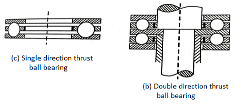
Fig. 14: Thrust ball bearing
Q15) Explain types of roller bearing.
A15)
Various types of roller bearings are as follows:
- Cylindrical Roller Bearings:
These bearings have short rollers guided in a cage. These bearings are relatively rigid against the radial motion and have the lowest coefficient of friction of heavy-duty rolling contact bearings.
b. Spherical roller bearing:
The self-aligning feature is achieved by grinding one of the races in the form of a sphere.
These bearings can normally tolerate angular misalignment in the order of +1.5 degree to -1.5 degree and when used with a double row of rollers, these can carry thrust load in either direction.
c. Needle Roller Bearing:
These bearings are relatively slender and fill the spaces so that neither a cage nor a retainer is needed. These bearings are used when heavy loads are to be carried with an oscillatory motion.
d. Tapered roller bearing:
Such kind of bearing can carry both radial and thrust loads. These bearings are available in various combinations such as double row bearing with different cone angles.

Fig. 15: Types of roller bearing
Unit - 4
Unit - 4
Unit - 4
Sliding Contract Bearing
Q1) Explain Sliding Contact Bearing Types in detail.
A1)
Sliding contact bearings are classified in three ways.
A. Based on type of load carried
B. Based on type of lubrication
C. Based on lubrication mechanism
A. Bearing classification based on type of load carried
(a). Radial bearings: These bearings carry only radial loads i.e. loads perpendicular to the axis of shaft
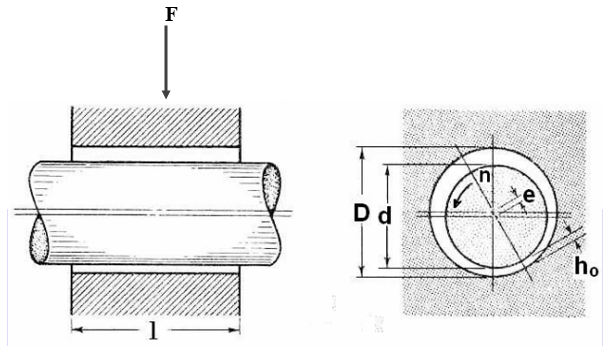
Fig. 1 Radial bearings
(b). Thrust bearings or axial bearings: These bearings carry only axial loads.
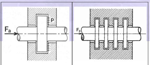
Fig.2(a) Single collar thrust bearing Fig. 2(b) Multiple collar thrust bearing
(c). Radial thrust bearings: These bearings carry both radial and thrust loads.
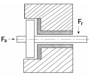
Fig. 3 Radial thrust bearing
B. Bearing classification based on type of Lubrication.
The type of lubrication means the extent to which the contacting surfaces are separated in a shaft bearing combination. This classification includes
(a) Thick film lubrication
(b) Thin film lubrication
(c) Boundary lubrication
(a). Thick film lubrication: As in Fig. (a) the surfaces are separated by thick film of lubricant and there will not be any metal-to-metal contact. The film thickness is anywhere from 8 to 20 μm. Typical values of coefficient of friction are 0.002 to 0.010. Hydrodynamic lubrication is coming under this category. Wear is the minimum in this case.
(b). Thin film lubrication: Here even though the surfaces are separated by thin film of lubricant, at some high spots Metal-to-metal contact does exist, Fig. 4 (b).Because of this intermittent contacts, it also known as mixed film lubrication. Surface wear is mild. The coefficient of friction commonly ranges from 0.004 to 0.10.

Fig. 4(a). Thick film lubrication (b) Thin film lubrication (c) Boundary lubrication
(c). Boundary lubrication: Here the surface contact is continuous and extensive as Shown in Fig (c). The lubricant is continuously smeared over the surfaces and provides a continuously renewed adsorbed surface film which reduces the friction and wear. The typical coefficient of friction is 0.05 to 0.20.
C. Bearing classification based on lubrication mechanism
(a). Hydrodynamic lubricated bearings: In these bearings the load-carrying surfaces are separated by a stable thick film of lubricant that prevents the metal-to-metal contact. The film pressure generated by the moving surfaces that force the lubricant through a wedge shaped zone. At sufficiently high speed the pressure developed around the journal sustains the load. This is illustrated in Fig 5.
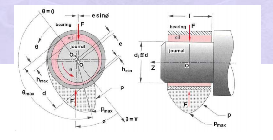
Fig. 5 Hydrodynamic lubricated bearings
(b). Hydrostatic lubricated bearings: In these bearings, externally pressurized lubricant is fed into the bearings to separate the surfaces with thick film of lubricant. These types of bearings do not require the motion of the surfaces to generate the lubricant film. Hence they can operate from very low speed to high speed. This is illustrated in Fig. 6
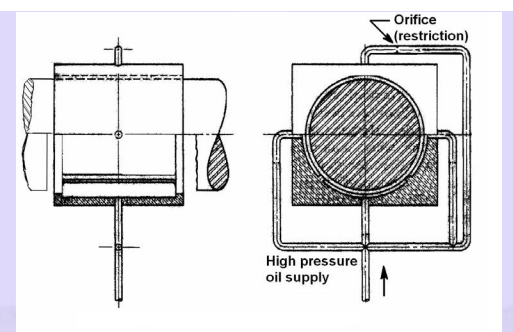
Fig. 6 Hydrostatic lubricated bearings
(c). Elastic hydrodynamic lubricated bearings: Rolling contact bearings come under this category. The oil film thickness is very small. The contact pressures are going to be very high. Hence to prevent the metal-to-metal contact, surface finishes are to be of high quality. Such a type of lubrication can be seen in gears, rolling contact bearings, cams etc.
(d). Boundary lubricated bearings: When the speed of the bearing is inadequate, less quantity of lubricant is delivered to the bearing, an increase in the bearing load, or an increase in the lubricant temperature resulting in drop in viscosity – any one of these may prevent the formation of thick film lubrication and establish continuous metal-to-metal contact extensively. Often bearings operating in such situations are called boundary lubricated bearings.
(e). Solid film lubricated bearings: For extreme temperature operations ordinary mineral oils are not satisfactory. Solid film lubricants such as graphite, molybdenum disulfide or their combinations which withstand high operating temperature are used. These types of bearings are common in furnace applications, hot drawing mills etc.
Q2) What is plain journal bearing?
A2)
The sliding contact bearing in which the sliding action is along the circumference of a circle and carrying radial loads are known as Plain Journal bearing or sleeve bearing.
Classification of Journal bearing:
The classifications of Plain journal bearing are mentioned below:
- Full journal bearing: In this bearing, the bearing completely covers the journal that is the angle of contact between the bearing and journal is 3600.
2. Partial Journal bearing: When the angle of contact between the bearing and journal is 1200. It is known as a journal bearing.
3. Fitted Journal Bearing: In this bearing, the contact angle is also1200 but there is no clearance between the bearings and the journal that is the diameter of bearing and journal are equal.
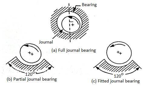
Fig. 7: Full, partial, fitted journal bearing
Q3) What is hydrodynamic lubrication?
A3)
Thick film lubrication is further divided into two groups: Hydrodynamic and Hydrostatic lubrication.
Hydrodynamic lubrication is defined as a system of lubrication in which the load-supporting fluid film is created by the shape and relative motion of the sliding surfaces.
Theory of Hydrodynamic Lubrication & Pressure Development in oil film:
The principle of hydrodynamic lubrication in journal bearings is shown in Fig. Initially, the shaft is at rest (a) and it sinks to the bottom of the clearance space under the action of load W. The surfaces of the journal and bearing touch during ‘rest’.
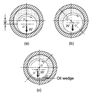
Fig.8 Hydrodynamic Lubrication (a) Journal at Rest (b) Journal Starts to Rotate (c) Journal at Full Speed
As the journal starts to rotate, it climbs the bearing surface (b) and as the speed is further increased, it forces the fluid into the wedge-shaped region (c). Since more and more fluid is forced into the wedge-shaped clearance space, pressure is generated within the system.
The pressure distribution around the periphery of the journal is shown in Fig. 16.2. Since the pressure is created within the system due to rotation of the shaft, this type of bearing is known as self-acting bearing. The pressure generated in the clearance space supports the external load (W). In this case, it is not necessary to supply the lubricant under pressure and the only requirement is sufficient and continuous supply of the lubricant. This mode of lubrication is seen in bearings mounted on engines and centrifugal pumps. Frequently, a term ‘journal’ bearing is used. A journal bearing is a sliding contact bearing working on hydrodynamic lubrication and which supports the load in radial direction. The portion of the shaft inside the bearing is called journal and hence the name ‘journal’ bearing.
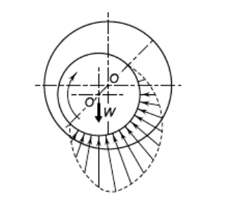
Fig. 9 Pressure Distribution in Hydrodynamic Bearing
Q4) Explain 2D Basic Reynolds Equation.
A4)
The theory of hydrodynamic lubrication is based on a differential equation derived by Osborne Reynold. This equation is based on the following assumptions:
(i) The lubricant obeys Newton’s law of viscosity.
(ii) The lubricant is incompressible.
(iii) The inertia forces in the oil fi lm are negligible.
(iv) The viscosity of the lubricant is constant.
(v) The effect of curvature of the fi lm with respect to film thickness is neglected. It is assumed that the fi lm is so thin that the pressure is constant across the fi lm thickness.
(vi) The shaft and the bearing are rigid.
(vii) There is a continuous supply of lubricant.
Fig. Shows a journal rotating in the clockwise direction supported by a film of lubricant of variable thickness h on a partial bearing, which is fixed. We specify that the journal has a constant surface velocity U. Using Reynolds’ assumption that curvature can be neglected, we fix a right-handed xyz reference system to the stationary bearing. We now select an element of lubricant in the film (Fig.a) of dimensions dx, dy, and dz, and compute the forces that act on the sides of this element.
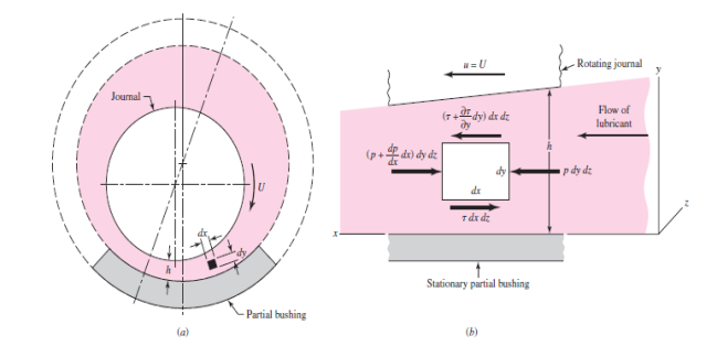
Fig. 10 An element of lubricant in the film
As shown in Fig, normal forces, due to the pressure, act upon the right and left sides of the element, and shear forces, due to the viscosity and to the velocity, act upon the top and bottom sides. Summing the forces in the x direction gives.

This reduces to

Also, we have

Where the partial derivative is used because the velocity u depends upon both x and y. Substituting Eq. (c) in Eq. (b), we obtain

Holding x constant, we now integrate this expression twice with respect to y. This gives


Note that the act of holding x constant means that C1 and C2 can be functions of x. We now assume that there is no slip between the lubricant and the boundary surfaces. This gives two sets of boundary conditions for evaluating the constants C1 and C2:
At y=0, u=0
At y=h, u=U
Notice, in the second condition, that h is a function of x. Substituting these conditions in Eq. (e) and solving for the constants gives


This equation gives the velocity distribution of the lubricant in the film as a function of the coordinate y and the pressure gradient dp/dx. The equation shows that the velocity distribution across the film (from y = 0 to y = h) is obtained by superposing a parabolic distribution onto a linear distribution.
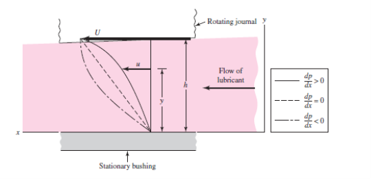
Fig 11. Velocity of the lubricant
Figure shows the superposition of these distributions to obtain the velocity for particular values of x and dp/dx. In general, the parabolic term may be additive or subtractive to the linear term, depending upon the sign of the pressure gradient. When the pressure is maximum, dp/dx = 0 and the velocity is

Which is a linear relation.
We next define Q as the volume of lubricant flowing in the x direction per unit time. By using a width of unity in the z direction, the volume may be obtained by the expression
Q =  (h)
(h)
Substituting the value of u from Eq. (6.1) and integrating gives

The next step uses the assumption of an incompressible lubricant and states that the flow is the same for any cross section. Thus

From equation (i)


Which is the classical Reynolds equation for one-dimensional flow. It neglects side leakage, that is, flow in the z direction. A similar development is used when side leakage is not neglected. The resulting equation is

There is no general analytical solution to Eq. (6.3); approximate solutions have been obtained by using electrical analogies, mathematical summations, relaxation methods, and numerical and graphical methods. One of the important solutions is due to Somerfield and may be expressed in the form

Where φ indicates a functional relationship. Somerfield found the functions for half-bearings and full bearings by using the assumption of no side leakage.
Q5) Explain Raimondi and Boyd method &Somerfield number
A5)
There is no exact solution to Reynold’s equation for a journal bearing having a finite length. However, AA Raimondi and John Boyd of Westinghouse Research Laboratory solved this equation on computer using the iteration technique. The results of this work are available in the form of charts and tables.
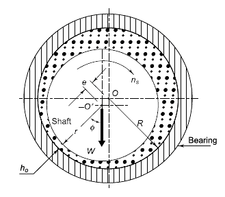
Fig 12
In Fig, O and O’ are the axes of bearing and journal respectively. The distance OO’ is called eccentricity and denoted by the letter ℇ. The radial clearance c is given by,
c=R-r
Where
c = radial clearance (mm)
R = radius of bearing (mm)
r = radius of journal (mm)
The eccentricity ratio ( ) is defined as the ratio of eccentricity to radial clearance.
Therefore

From Fig.
R=e+r+ho
Where,
ho = minimum fi lm thickness (mm)
Thus equation 6.5 became

The Somerfield number is given by

Where
S = Somerfield number (dimensionless)
u = viscosity of the lubricant (N-s/mm2) or (MPa-s)
ns = journal speed (rev./s)
p = unit bearing pressure, i.e., load per unit of the projected area (N/mm2)
The Somerfield number contains all variables, which are controlled by the designer.
Q6) What are thermal considerations?
A6)
Heat is generated in the bearing due to viscosity of the lubricating oil. The frictional work is converted into heat, which increases the temperature of the lubricant. Assuming that the total heat generated in the bearing is carried away by the total oil flow in the bearing, the expression for temperature rise can be determined. From Eq. (6.7),
(kW)f = (2πns)(fWr)(10-6)
Where
f = coefficient of friction =  CFV
CFV
CFV = coefficient of friction variable
W = 2plr,
p = unit bearing pressure
r = radius of journal (mm)
l = length of bearing (mm)
The heat generated (Hg) is given by,
Hg = (kW)f = (2πns)(fWr)(10-6)
Which reduces to
Hg = (4π)(10-6) rcns lp (CFV)
The heat carried away by oil flow (Hc) is given by,
Hc = m Cp Δt
Where,
m = mass of the lubricating oil passing throughthe bearing (kg/s)
Cp = specifi c heat of lubricating oil (kJ/kgºC)
∆t = temperature rise (°C)
The mass of the lubricating oil is given by,
m = ρQ (10-6) kg/s
Substituting
Q = rcns/(FV)
The mass is given by
m = ρ(rcnsl)(FV) (10-6) kg/s
Substituting the value of m in Hc
Hc = Cp Δt ρ(rcnsl) (FV)(10-6)
Equating the expressions for Hg and Hc,

For most lubricating oils,
ρ = 0.86 and Cp = 1.76 kJ/kgoC
Substituting these values in Eq. (16.22),

The average temperature of the lubricating oil is given by
Tav = Ti + 
Where Ti is the inlet temperature.
Q7) What are the parameters of bearing design?
A7)
In the preliminary stages of journal bearing design, it is required to select suitable values for the following parameters:
(i) length-to-diameter ratio
(ii) Unit bearing pressure
(iii) Radial clearance
(iv) Minimum oil film thickness
(i) Length to Diameter Ratio: In the design of hydrodynamic bearings, the diameter of the shaft is determined by strength or rigidity considerations and not on the basis of bearing capacity. Therefore, it is the bearing length that the designer has to decide to obtain a given bearing capacity. The length to diameter ratio (l/d) affects the performance of the bearing. As the ratio increases, the resulting film pressure increases as shown in Fig.
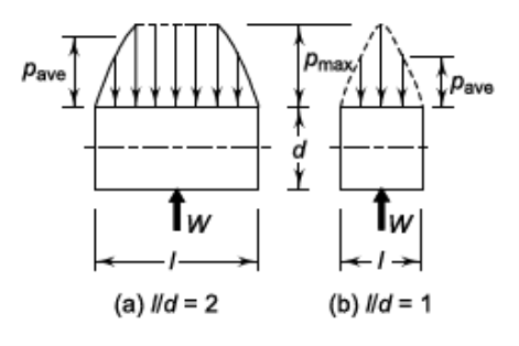
Fig. 13 Effect of (l/d) ratio on Average Bearing Pressure
A long bearing, therefore, has more load carrying capacity compared with a short bearing. A short bearing, on the other hand, has greater side flow, which improves heat dissipation. Therefore, the design trend is to use (l/d) ratio as 1 or less than 1. When the shaft and the bearing are precisely aligned, the shaft deflection is within the limit and cooling of lubricant and bearing does not present a serious problem, the (l/d) ratio can be taken as more than 1. In practice, the (l/d) ratio varies from 0.5 to 2.0, but in the majority of applications, it is taken as 1 or less than 1.
(ii) Unit Bearing Pressure: The unit bearing pressure is the load per unit of projected area of the bearing in running condition. It depends upon a number of factors, such as bearing material, operating temperature, the nature and frequency of load and service conditions. The values of unit bearing pressure, based on past experience, are given in Table.
Table: Permissible bearing pressures
S.No. | Application | Unit bearing pressure (p) (N/mm2) |
1 | Diesel engines Main bearing Crank pin Gudgeon pin |
5-10 7-14 13-14 |
2 | Automotive engines Main bearing Crank pin |
3–4 10–14 |
3 | Air compressors Main bearing Crank pin |
1–1.5 1.5–3.0 |
4 | Centrifugal pumps Main bearing |
0.5–0.7 |
5 | Electric motors Main bearing |
0.7–1.5 |
6 | Transmission shafting Light duty Heavy duty |
0.15 1.00 |
7 | Machine tools Main bearing |
2 |
(iii) Radial Clearance: The radial clearance should be small to provide the necessary velocity gradient. However, this requires costly finishing operations, rigid mountings of the bearing assembly and clean lubricating oil without any foreign particles. This increases the initial and maintenance costs. The practical value of radial clearance is 0.001 mm per mm of the journal radius. Or, c = (0.001) r
(iv) Minimum Oil Film Thickness: The surface finish of the journal and the bearing is governed by the value of the minimum oil fi lm thickness selected by the designer and vice versa. There is a lower limit for the minimum oil fi lm thickness, below which metal to metal contact occurs and the hydrodynamic film breaks. This lower limit is given by, h0 = (0.0002) r
Q8) Explain properties and materials.
A8)
The properties of the lubricant used are as follows:
- Viscosity: The viscosity is a measure of the fluidity of a fluid. It is a physical property by virtue of which oil is able to form, retain, and offer resistance to shear a buffer film under heat and pressure.
- Oiliness: It is the measure of the lubricating qualities under boundary conditions where base metal to metal contact is prevented only by the absorbing film.
- Density: The density is a measure of the dynamic and kinematic viscosity of a lubricant.
- Viscosity Index: It is used to denote the variation of viscosity with the temperature.
- Flash Point: It is the lowest temperature at which an oil gives off sufficient vapour to support a momentary flash without actually setting fire to the oil when a flame is brought within 6 mm at the surface of the oil.
- Fire Point: It is the temperature at which oil gives off sufficient vapour to burn it continuously when ignited.
- Pour point: It is the temperature at which oil will cease to flow when cooled.
Q9) Explain lubricants and lubrication.
A9)
The lubricants are used in bearings to reduce friction between the rubbing surfaces and to carry away the heat generated by friction.
It also protects the bearings against corrosion.
Types of Lubricant:
- Liquid Lubricant: The liquid lubricants used in bearing are mineral oil and synthetic oil. These are widely used because of their low cost, stability, and easy availability.
- Semi-solid lubricant: The semi-solid lubricant is grease. The semi-solid lubricant has a higher viscosity than oil. These are used where slow speed and heavy pressure exist.
- Solid Lubricant: The solid lubricants are graphite and molybdenum. The solid lubricants are extremely useful where oil films cannot be maintained because of high pressure and temperature.
Lubrication:
It is the science of reducing friction by application of a suitable substance called lubricant, between the rubbing surfaces of bodies having relative motion.
The objective of lubrication:
- To reduce friction.
- To reduce or prevent wear.
- To carry away heat generated due to friction.
- To protect the journal from corrosion.
Q10) Explain hydrodynamic journal bearing.
A10)
The following terms are used in hydrodynamic journal bearing.
Diameter clearance:-it is the difference between the diameters of the bearing and the journal mathematically , diametric clearance,
c=D-d
D=diameter of the bearing, and
d=diameter of the journal
Radial clearance: - it is the difference between the radio of the bearing and the journal. Mathematically, radial clearance.

Diametrical clearance ratio:- it is the ratio of the diameter clearance to the diameter of the journal. Mathematically,
Diametrical clearance ratio =
Eccentricity: -it is the radial distance between the centre (o) of the bearing and the displaced centre.  Of the bearing under load. It is denoted by e.
Minimum oil film thickness:-it is the minimum distance between the bearing and the journal, under complete lubrication condition. It is denoted by  and occurs at the line of the centres as shown in fig. 3.11.1. It is value may be assumed as C/4.
Attitude or eccentricity ratio:-it is the ratio of the eccentricity to the radial clearance so mathematically , attitude oe eccentricity ratio .

Q11) Explain heat generation in detail.
A11)
Heat generated in the bearing is due to the fluid friction and friction of the parts having relative motion.
Heat generated in bearing is given as,

Where,
 =coefficient of friction
P=unit pressure (Pa),
A= projected area ( ),
),
V=rubbing velocity (m/s)= , and
, and
W= load on the bearing (N)
Heat dissipated is given as ,

C= heat dissipation co-efficient,
A= projected area
 =temperature of bearing surface
 , and
, and
 =temperature of surrounding air
The value of C for general bearing may be taken as,
- For unventilated bearings ( still air ),

2. For well ventilated bearings ,

It has been shown by the experiments that temperature  is approximately midway between temperature of the oil
  and
and 
In other words

Q12) Explain design of journal bearing
A12)
Following are the procedure for the design of journal bearing
- Bearing Dimension: Calculate the bearing length (when the bearing load, diameter, and speed of shaft are known).
- Check the bearing pressure from the datebook, for probable satisfactory value.
- Now assume a lubricant from the data book, and its operating temperature (t0). This temperature should be in the range of 26.5 to 60 degree
- Calculate the value of Somerfield number that is ZN/p, for the assumed bearing temperature and check this value with the corresponding value from the datebook, for determining the possibility of maintaining fluid film operation.
- Now, assume a clearance ratio of that (C/D) from the datebook.
- Calculate coefficient of friction (µ) =0.326/106(ZN/p)(d/c)+k
- Calculate the heat generated by using, Qg=µWV
- Calculate the heat dissipation, Qd=CA(tb-ta)
- Calculate Thermal equilibrium to see that the heat dissipated becomes at least equal to the heat generated.
Q13) Explain rolling Contact Bearing Advantages and disadvantages.
A13)
In rolling Contact Bearing, the contact between the bearing surfaces is rolling instead of sliding as in plain bearing. Since the rolling friction is very less as compared to sliding friction such as bearing is also known as antifriction bearings.
Advantages
- Low starting and running friction except at very high speeds.
- Both radial and thrust loads can be carried by these bearings.
- Ability to withstand momentary shock loads without failure.
- Accuracy of shaft alignment.
- Easy replacement.
- Small overall dimensions.
- Reliability of service.
- Easy to mount and erect.
- Simple lubrication.
- Wear is practically nil.
Disadvantages
- Noisier at high speed.
- Low resistance to shock loading.
- More initial cost
- 4 Complicated Design of bearing house
4. Sensitive to dirt, etc.
Q14) What is thrust ball bearing?
A14)
A thrust ball bearing consists of a row of balls running between two rings, the shaft ring, and the housing ring.
Thrust ball bearings carry thrust load in only one direction and cannot carry any radial load.
The use of a large number of balls results in high thrust load carrying capacity in smaller space. These are used where heavy thrust loads are to be carried, for example, worm gear and crane hooks.
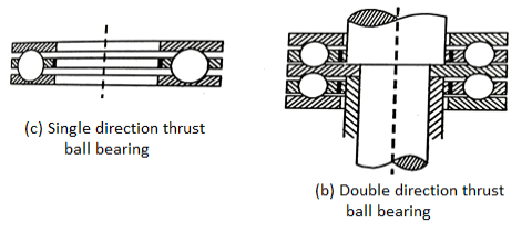
Fig. 14: Thrust ball bearing
Q15) Explain types of roller bearing.
A15)
Various types of roller bearings are as follows:
- Cylindrical Roller Bearings:
These bearings have short rollers guided in a cage. These bearings are relatively rigid against the radial motion and have the lowest coefficient of friction of heavy-duty rolling contact bearings.
b. Spherical roller bearing:
The self-aligning feature is achieved by grinding one of the races in the form of a sphere.
These bearings can normally tolerate angular misalignment in the order of +1.5 degree to -1.5 degree and when used with a double row of rollers, these can carry thrust load in either direction.
c. Needle Roller Bearing:
These bearings are relatively slender and fill the spaces so that neither a cage nor a retainer is needed. These bearings are used when heavy loads are to be carried with an oscillatory motion.
d. Tapered roller bearing:
Such kind of bearing can carry both radial and thrust loads. These bearings are available in various combinations such as double row bearing with different cone angles.

Fig. 15: Types of roller bearing