Unit-2
Cams, Gears and Gear trains
Q1) Define Cam and explain its types.
A1) Cams are the devices used for converting rotation motion into reciprocating motion. The motion created can be complex or regular and simple and irregular. As the cam rotates, turned by the circular motion, the cam follower traces the surface of the cam transmitting its motion to the required mechanism. The design of cam follower is quite important in the way the profile of the cam is followed. A fine pointed follower will more accurately trace the outline of the cam. This more accurate movement is at the expense of the strength of the cam follower.
Cams can be classified based on their physical shape.
Disk or plate cam: The disk (or plate) cam has an irregular contour to impart a specific motion to the follower. The follower moves in a plane perpendicular to the axis of rotation of the cam shaft and is held in contact with the cam by springs or gravity.
Cylindrical cam: The cylindrical cam has a groove cut along its cylindrical surface. The roller follows the groove, and the follower moves in a plane parallel to the axis of rotation of the cylinder.
Translating cam: The translating cam is a contoured or grooved plate sliding on a guiding surface(s).The follower may oscillate (Fig.3 a) or reciprocate (Fig. 3b).The contour or the shape of the groove is determined by the specified motion of the follower.
Q2) Draw the cam profile for following conditions:
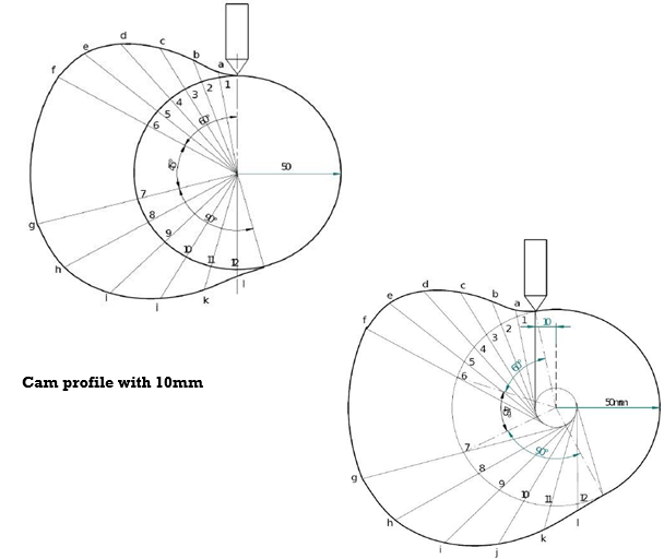
Follower type = Knife edged, in-line; lift = 50mm; base circle radius = 50mm; outstroke with SHM, for 60°cam rotation; dwell for 45°cam rotation; return stroke with SHM, for 90° cam rotation; dwell for the remaining period. (2) Draw the cam profile for the same operating condition so f with the follower offset by 10mm to the left of cam center.
A2)

Q3) Draw the cam profile for following conditions:
Follower type=roller follower, in-line; lift=25mm; base circle radius = 20mm; roller radius = 5mm; out stroke with Uniform acceleration and retardation, for 120° cam rotation; dwell for 60° cam rotation; return stroke with Uniform acceleration and retardation, for 90° cam rotation; dwell for the remaining period. Draw the cam profile for conditions same with follower off set to right of cam center by 5mm and cam rotating counter clockwise.
A3) Displacement Diagram:

Q4) Draw the cam profile for following conditions:
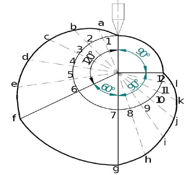
Follower type=knife edge d follower, in line; lift=30mm;base circle radius =20mm;outstroke with uniform velocity in 120°of cam rotation and dwell for 60°; return stroke with uniform velocity, during 90°of cam rotation; dwell for the remaining period.
A4) Displacement Diagram

Cam profile
Q5) Draw the cam profile for following conditions:
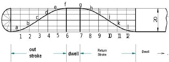
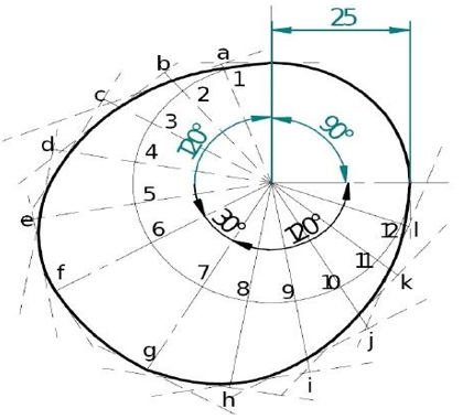
Follower type = flat faced follower, inline; follower rises by 20mm with SHM in 120° of cam rotation, dwells for 30° of cam rotation; returns with SHM in 120° of cam rotation and dwells during the remaining period. Base circle radius =25mm.
A5) Displacement Diagram:
Cam profile
Q6) Define epicyclic gear train.
A6)
Planetary gears solve the following problem. Let's say you want a gear ratio of 6:1 with the input turning in the same direction as the output. One way to create that ratio is with the following three-gear train:
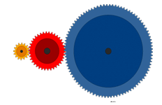
In this train, the blue gear has six times the diameter of the yellow gear (giving a 6:1 ratio). The size of the red gear is not important because it is just there to reverse the direction of rotation so that the blue and yellow gears turn the same way. However, imagine that you want the axis of the output gear to be the same as that of the input gear. A common place where this same-axis capability is needed is in an electric screwdriver.
Q7) What is velocity of gear trains?
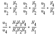
A7) We know that the velocity ratio of a pair of gears is the inverse proportion of the diameters of their pitch circle, and the diameter of the pitch circle equals to the number of teeth divided by the diametric pitch. Also, we know that it is necessary for the mating gears to have the same diametral pitch so that to satisfy the condition of correct meshing. Thus, we infer that the velocity ratio of a pair of gears is the inverse ratio of their number of teeth.
These equations can be combined to give the velocity ratio of the first gear in the train to the last gear:
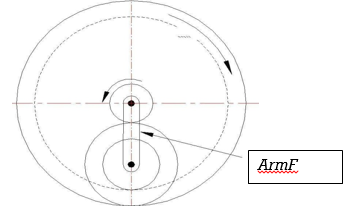
Q8) In a compound epicyclic gear train as shown in the figure, has gears A and an annular gears D & E free to rotate on the axis P. B and C is a compound gear rotate about axis Q. Gear A rotates at 90 rpm CCW and gear D rotates at 450 rpm CW. Find the speed and direction of rotation of arm F and gear E. Gears A, B and C are having 18, 45 and 21 teeth respectively. All gears having same module and pitch.
A8)
TA=18; TB=45; TC=21; NA=-90rpm; ND=450rpm:
Since the module and pitch are same for all gears :
the number of teeth on the gears is proportional to the pitch cirlce :
rD =rA +rB +rC
TD =TA +TB +TC
TD =18 +45 +21 =84 teeth on gear D
Gears A and D rotates in the opposite directions:
Train value=- TA/TB*Tc/TD
-(18*21)/(45*84)=(450-NF)/(-90-NF)
NF= Speed of Arm =400.9rpm-CW
Now consider gears A, B and E:
rE =rA +2rB
TE =TA +2TB
TE =18 +2*45
TE =108 =Number of teeth on gear E
Q9) What is Gear train? Explain with its type?
A9) A gear train is two or more gear working together by meshing their teeth and turning each other in a system to generate power and speed. It reduces speed and increases torque. To create large gear ratio, gears are connected together to form gear trains. They often consist of multiple gears in the train. The smaller gears are one-fifth of the size of the larger gear. Electric motors are used with the gear systems to reduce the speed and increase the torque. Electric motor is connected to the driving end of each train and is mounted on the test platform. The output end of the gear train is connected to a large magnetic particle brake that is used to measure the outputtorque.
Types of gear trains
Q10) Define Simple and Compound gear train.
A10) Simple Gear Train
The most common of the gear train is the gear pair connecting parallel shafts. The teeth of this type can be spur, helical or herringbone. There is only single gear for each axis. The angular velocity is simply the reverse of the tooth ratio. The main limitation of a simple gear train is that the maximum speed change ratio is 10:1. For larger ratio, large sizes of gear trains are required. The sprockets and chain in the bicycle is an example of simple gear train. When the paddle is pushed, the front gear is turned and that meshes with the links in the chain. The chain moves and meshes with the links in the rear gear that is attached to the rear wheel. This enables the bicycle to move.
Compound Gear Train
For large velocities, compound arrangement is preferred. Two keys are keyed to a single shaft. A double reduction train can be arranged to have its input and output shafts in a line, by choosing equal center distance for gears and pinions. Two or more gears may rotate about a single axis