Unit-3
Force Analysis
Q1) What is equilibrium?
A1) A rigid body is said to be in equilibrium if it continues it continues its state of motion
The conditions of equilibrium can be written mathematically as:
∑M=0
∑F=0
Q2) Define Static force analysis.
A2) The analysis is carried out by determining all the forces and couples acting on all the pairs. In this analysis, we ignore the forces due to acceleration. Only the effects of external forces applied to the mechanism are considered.
Q3) What are the conditions for a body to be equilibrium under the action of two forces?
A3) Two forces System- Fig. 1, shows a member under the action of two forces. The body will be equilibrium if

Fig. 1: Two forces System
Q4) Explain D’ Alembert Principle.
A4) It states that “the inertia force and couples, the external forces and torques on a body together give statical equilibrium.
Inertia Force, Fi=-ma
Inertia Couples, Ci=-Igα, where, m= Mass of body,
a= Acceleration of centre of mass of body.
Ig= Moment of inertia about an axis passing through the centre of mass and perpendicular to plane of rotation of body.
α= Angular acceleration of the body.
Let, F1, F2, F3= External forces acting on the body, and
T1, T2, T3 = External torques on the body about its centre of mass.
Now, according to the principle, ∑F+Fi=0, and ∑T+Ci=0.
The above equations are similar to the equation of body in static equilibrium.
Q5) The crank of a slider crank mechanism rotates at constant speed of 250 rpm. The crank is 150 mm and the connecting rod is 500 mm long. Determine the angular velocity and the angular acceleration of the connecting rod at the crank angle of 45 degree from the inner dead centre position.
A5)
Given:- N=250rpm , r=150mm=0.5m,l=500mm=0.5m, 
to find = i. angular velocity ii. angular acceleration


2. We know that,

3. Now, angular velocity of connection rod is,


Q6) Define Turning moment diagram for four stroke cycle internal combustion engine.
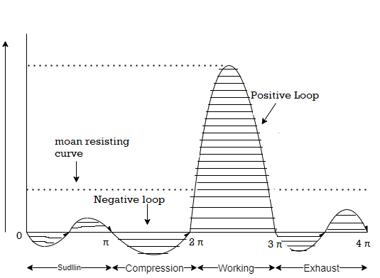
A6) A turning moment diagram for a four stroke cycle internal combustion engine is shown in Fig below, we know that in a four stroke cycle internal combustion engine; there is one working stroke after the crank has turned through two revolutions, i.e. 720° (or 4 π radians).

Fig 2: Turning moment diagram for a four stroke cycle internal combustion engine.
Since the pressure inside the engine cylinder is less than the atmospheric pressure during the suction stroke, therefore a negative loop is formed as shown in Fig. 16.2. During the compression stroke, the work is done on the gases, therefore a higher negative loop is obtained. During the expansion or working stroke, the fuel burns and the gases expands, therefore a large positive loop is obtained. In this stroke, the work is done by the gases. During exhaust stroke, the work is done on the gas, therefore a negative loop is formed. It may be noted that the effect of the inertia forces on the piston is taken into account in above figure.
Q7) Derive expression for coefficient of fluctuation of speed.
A7) The difference between the maximum and minimum speeds during a cycle is called the maximum fluctuation of speed. The ratio of the maximum fluctuation of speed to the mean speed is called the coefficient of fluctuation of speed.
Let N1 and N2 = Maximum and minimum speeds in r.p.m. during the cycle, and

Coefficient of fluctuation of speed

Q8) The turning moment diagram for a multi cylinder engine has been drawn to a scale 1 m m = 600 N-m vertically and 1 m m = 3° horizontally. The intercepted areas between the output torque curve and the mean resistance line, taken in order from one end, are as follows:
+ 52, – 124, + 92, – 140, + 85, – 72 and + 107 m m2, when the engine is running at a speed of 600 r.p.m. If the total fluctuation of speed is not to exceed 1.5% of the mean, find the necessary mass of the flywheel of radius 0.5 m.
A8) Given: N = 600 r.p.m. or ω = 2 π × 600 / 60 = 62.84 rad / s ; R = 0.5 m

Since the total fluctuation of speed is not to exceed 1.5% of the mean speed, therefore ω1 – ω
2 = 3% ω = 0.03 ω
And coeffecient of fluctuation of speed,

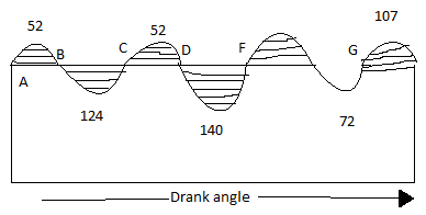
The turning moment diagram is shown in fig. 16.7
Since the tunning moment scale is 1mm =600N-m and crank angle scale is 1mm= therefore
1 on turning moment diagram

Let the total energy at A = E, then referring to Fig. 16.7,
Energy at B= E+ 52...(Maximum energy)
Energy at C= E + 52 – 124 = E –72 Energy at D = E – 72 + 92 = E + 20
Energy at E= E + 20 – 140 = E–120...(Minimum energy)
Energy at F = E – 120 + 85 = E – 35 Energy at G = E – 35 – 72 = E – 107
Energy at H = E – 107 + 107 = E = Energy at A
We know that maximum fluctuation of energy,
∆ E = Maximum energy – Minimum energy
= (E + 52) – (E – 120) = 172 = 172 × 31.42 = 5404 N-m
Let m = Mass of the flywheel in kg.
We know that maximum fluctuation of energy (∆ E ),
5404 =m.R.CS = m × (0.5) × (62.84) × 0.03 = 29.6m
m = 5404 / 29.6 = 183 kg
Q9) Derive expression for maximum fluctuation of flywheel.
A9) Let ,
 = maximum speed during the cycle
 = minimum speed during the cycle.
N= mean speed of flywheel, 
And  = co-efficient of fluctuation of speed =
The mean kinetic energy of the flywheel ,

The maximum fluctuation of eenergy in a flywheel ,


Q10) The radius of gyration of a flywheel is 1 meter and fluctuation of speed is not to exceed 1% of the mean speed of the flywheels. If the mass of the flywheel is 3340 kg and the steam develops 150 kW at 135 rpm, then find Maximum fluctuation energy and coefficient of fluctuation of energy.
Given :-
To find:- i. maximum fluctuation of energy
ii. co-efficient of fluctuation of energy
A10)
1. Maximum fluctuation of energy


We know that , work done per cycle =

=66666.667 N-m
2. Co-efficient of fluctuation of energy

