UNIT 2
OPTICS
Q1) Explain Production of Polarized Light by Reflection?
A1)
Brewster’s law can be used to polarise the light by reflection. When unpolarized light is incident on the boundary between two transparent media, the reflected light is polarised with its electric vector perpendicular to the plane of incidence when the refracted and reflected rays make a right angle with each other.
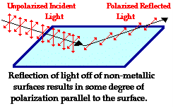
Thus we have seen that when the reflected wave is perpendicular to the refracted wave, the reflected wave is totally polarised. The electric field vectors of all unpolarized light may be resolved into two components as follows;
The angle of incidence, in this case, is called Brewster’s angle
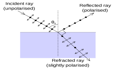 
If the angle of incidence θi is varied, the reflected coefficient ‘r’ for the em waves corresponding to the tangential component will vary as shown in the figure. As θi increases r will decrease. At θi = Brewster angle (about 57° for glass) r will be zero and no reflection of the tangential component will take place. The reflected beam will contain light waves having only the normal component for the electric field as shown in the figure that is the reflected light will be plane-polarized with the oscillations of electric field vector normal to the plane of incidence. Cause of Polarization by Reflection The em waves are generated because of the oscillation of electric charge. The electric field vectors of the transmitted ray act on the electrons in the dielectric. Since the intensity of em wave emitted by the oscillating charge is maximum in a direction normal to the plane of oscillation, and zero along the line of oscillations for the plane-polarized light having electric field vector in the plane of incidence, there will be no emission of em waves in a direction normal to the reflected ray. In the figure, the direction along which no emission should occur is called a zero intensity line. Let the angle between the reflected ray and the zero intensity line be 𝛿 the angle between the reflected and transmitted ray is π/2 + 𝛿 suppose we arrange the angle of incidence such that n=sinθi / sinθr n=sinθi / sin(π/2 – θi) n=sinθi / cosθi n=tan θi That is possible when θi + θr = π/2 according to Brewster’s law From figure θi + θr+ π/2 + = π As θi + θr = π/2 So π/2+ π/2 + = π = 0 The line of zero intensity and the reflected ray will coincide. Thus there will be no reflection of light when the angle of incidence is equal to Brewster’s angle. Thus the unpolarized light can be polarized by reflection as the reflected beam will contain light waves having electric field vector oscillating along normal to the plane of the incidence only. |
Q2) Explain the term optical activity and specific rotation?
A2)
Optical Activity The optical activity was first observed in quartz crystals in 1811 by a French physicist, François Arago. Louis Pasteur was the first to recognize that optical activity arises from the dissymmetric arrangement of atoms in the crystalline structures or in individual molecules of certain compounds. Optical activity, the ability of a substance to rotate the plane of polarization of a beam of light that is passed through it. (In plane-polarized light, the vibrations of the electric field are confined to a single plane. The intensity of optical activity is expressed in terms of a quantity, called specific rotation, defined by an equation that relates the angle through which the plane is rotated, the length of the light path through the sample, and the density of the sample (or its concentration if it is present in a solution). Because the specific rotation depends upon the temperature and upon the wavelength of the light, these quantities also must be specified. The rotation is assigned a positive value if it is clockwise with respect to an observer facing the light source, negative if counterclockwise. A substance with a positive specific rotation is described as dextrorotatory and denoted by the prefix d or (+); one with a negative specific rotation is levorotatory, designated by the prefix l or (-). Optical activity is the ability of a chiral molecule to rotate the plane of plane-polarised light, measured using a polarimeter. A simple polarimeter consists of a light source, polarising lens, sample tube, and analyzing lens.  When light passes through a sample that can rotate plane polarised light, the light appears to dim because it no longer passes straight through the polarising filters. The amount of rotation is quantified as the number of degrees that the analyzing lens must be rotated by so that it appears as if no dimming of the light has occurred. Measuring Optical Activity When rotation is quantified using a polarimeter it is known as an observed rotation, because rotation is affected by path length (l, the time the light travels through a sample) and concentration (c, how much of the sample is present that will rotate the light). When these effects are eliminated a standard for comparison of all molecules is obtained, the specific rotation, [a]. [a] = 100a / cl when concentration is expressed as g sample /100ml solution Enantiomers will rotate the plane of polarisation in exactly equal amounts (same magnitude) but in opposite directions. As already discussed Dextrorotary designated as d or (+), clockwise rotation (to the right) Levorotary designated as l or (-), anti-clockwise rotation (to the left). If only one enantiomer is present a sample is considered to be optically pure. When a sample consists of a mixture of enantiomers, the effect of each enantiomer cancels out, molecule for molecule. For example, a 50:50 mixture of two enantiomers of a racemic mixture will not rotate plane polarised light and is optically inactive. A mixture that contains one enantiomer excess, however, will display a net plane of polarisation in the direction characteristic of the enantiomer that is in excess. |
Q3) Explain Photoelasticity?
A3)
Photoelasticity, the property of some transparent materials, such as glass or plastic, while under stress, to become doubly refracting (i.e., a ray of light will split into two rays at entry). Optical elements The method of photoelasticity requires the use of two types of optical elements—the polarizer and the wave plate. Polarizer: A polarizer is an element that converts randomly polarized light into plane-polarized light. It was the introduction of large polarizing sheets by Polaroid Corporation in 1934 that led to the rapid advance of photoelasticity is a stress-analysis tool. Before that, small naturally occurring crystals were used for this purpose. In the figure, a single light wave with arbitrarily oriented wave amplitude approaches the polarizer from the left. As this wave encounters the polarizer, it is resolved into two vector components—one parallel to the polarizing direction of the 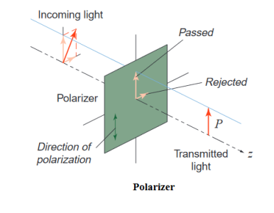 Polarizer, and one perpendicular to it. The parallel component is passed, but the perpendicular one is rejected. Light emanating from the polarizer is therefore plane-polarized in the direction of polarization of the polarizer. Viewed in ordinary (unpolarized) light, a polarizer always looks dark because half the light striking it is rejected. Wave plate: A wave plate resolves incident light into two components, but instead of rejecting one of these components, it retards it relative to the other component. 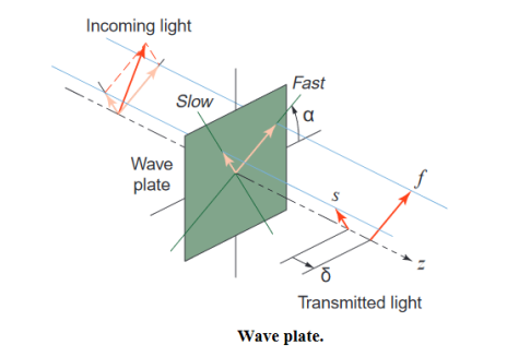 In the figure, the “fast” axis of the wave plate makes an angle α with respect to an arbitrarily chosen reference direction. The component f of the incident light with amplitude vector in this orientation is retarded somewhat as it passes through the wave plate. However, the orthogonal component is retarded, even more, resulting in a phase lag δ between this “slow” component and the “fast” one. The term double refraction is often used to describe this behaviour. Waveplates may be either permanent or temporary. A permanent wave plate has a fixed fast-axis orientation α and a fixed relative retardation δ. Such wave plates have their use in photo-elasticity, as will be seen subsequently. A temporary wave plate can produce double refraction in response to mechanical stimulus. Photoelastic specimens are temporary wave plates. Photoelastic materials are birefringent, that is, they act as temporary wave plates, refracting light differently for different light-amplitude orientations, depending upon the state of stress in the material. When photoelastic materials are subjected to pressure, internal strains develop that can be observed in polarized light; i.e., light vibrating normally in two planes, which has had one plane of vibration removed by passing through a substance called a polarizer. Two polarizers that are crossed ordinarily do not transmit light, but if a stressed material is placed between them and if the principal axis of the stress is not parallel to this plane of polarization, some light will be transmitted in the form of coloured fringes. Stresses in opaque mechanical structures can be analyzed by making models in plastic and studying the fringe pattern under polarized light, which may be either white (a mixture of all wavelengths) or a single wavelength.
|
Q4) Explain Polarization by half-wave and quarter-wave plate?
A4)
A wave plate or retarder is an optical device that alters the polarization state of a light beam traveling through it. There are many types of retarders. Some common retarders are quarter-wave (λ/4) plates and half-wave(λ/2) plates. A half-wave plate functions as a polarization rotator for linearly polarized light. It rotates the polarization of a linearly polarized light by twice the angle between its optic axis and the initial direction of polarization, as shown in Figure 28. It introduces a phase difference of radians between the A typical wave plate is simply a birefringent crystal or a double refracting plastic foil with a carefully chosen thickness. If a beam of parallel light strikes perpendicularly a wave plate the light beam is split into two components due to its double refracting properties. The two components have planes of oscillation perpendicular to each other and slightly different phase velocities. For a quarter-wave plate, the thickness of the foil is chosen in such a manner that the light component whose electric field vector oscillates in parallel to the rotation lever lags by a λ/4 behind other perpendicular oscillating light components. For a half-wave plate, the thickness is chosen so that the created phase difference has the amount of λ/2. In this experiment monochromatic light falls on a quarter-wave and half-wave plate. The polarization of the emergent light is investigated at different angles between the optic axis of the wave plates and the direction of the incident light. 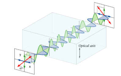 Half-wave plate A half-wave plate functions as a polarization rotator for linearly polarized light. It rotates the polarization of a linearly polarized light by twice the angle between its optic axis and the initial direction of polarization, as shown in Figure 22. It introduces a phase difference of radians between the two components of the electric field vectors. Suppose a plane-polarized wave is normally incident on a wave plate, and the plane of polarization is at an angle ϕ with respect to the fast axis, as shown. After passing through the plate, the original plane wave has been rotated through an angle 2ϕ. 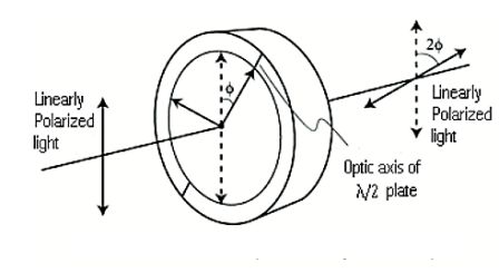 A half-wave plate is very handy in rotating the plane of polarization from a polarized laser to any other desired plane (especially if the laser is too large to rotate). Most large ion lasers are vertically polarized. To obtain horizontal polarization, simply place a half-wave plate in the beam with its fast (or slow) axis 45° to the vertical. The l/2 plates can also change left circularly polarized light into right circularly polarized light or vice versa. The thickness of the half waveplate is such that the phase difference is 1/2 wavelength (l/2, Zero order) or a certain multiple of 1/2-wavelength [(2n+1)l/2, multiple order]. Quarter Wave Plate A quarter-wave plate is used to convert linear polarization to circular polarization and vice-versa. To obtain circular polarization, the amplitudes of the two E vector components must be equal and their phase difference must be 90 or 270 degrees. A quarter-wave plate is capable of introducing a phase difference of 90 degrees between the two components of the incident light. However, this is not enough to produce circular polarization. The direction of polarization of the incident light with respect to the optic axis of the quarter-wave plate is equally important. It is obvious that the amplitudes of the two components will be equal only when the incident linear polarization direction makes an angle of 45 degrees with respect to the optic axis of the crystal(i.e.α= 45degrees). Figure 30 illustrates the conversion of linearly polarized light into circularly polarized light. Note that conversely, if circularly polarized light is incident on a quarter-wave plate, the resulting polarization will be linear, at an angle of 45 degrees with respect to the optic axis. Again, the reason is that a phase difference of 90 degrees is introduced between the two components of the electric field vector, which traces a helix-like path as the circularly polarized wave propagates. 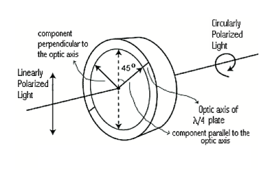 |
Q5) What is the difference between Fresnel’s diffraction and Fraunhofer's diffraction?
A5)
Fresnel Diffraction | Fraunhofer diffraction |
1 If the source of light and screen is at a finite distance from the obstacle, then the diffraction is called Fresnel diffraction. | 1 If the source of light and screen is at an infinite distance from the obstacle then the diffraction is called Fraunhofer diffraction. |
2 The corresponding rays are not parallel. | 2 The corresponding rays are not parallel. |
3 The wavefronts falling on the obstacle are not plane. | 3 The wavefronts falling on the obstacle are planes. |
4 No convex lens is needed to converge spherical wavefronts. | 4 Plane diffracting wavefronts are converged by means of a convex lens to produce a diffraction pattern. |
5 Fresnel diffraction patterns on flat surfaces. | 5 Fraunhofer diffraction patterns on spherical surfaces. |
6 Diffraction patterns Change as we propagate them further ‘downstream’ of the source of scattering. | 6 Diffraction patterns Shape and intensity of a Fraunhofer diffraction pattern stay constant. |
7 To obtain Fresnel diffraction, zone plates are used. | 7 To obtain Fraunhofer diffraction, the single-double plane diffraction grafting is used. |
8 Diffraction pattern moves along the corresponding shift in the object. | 8 Diffraction pattern remains in a fixed position. |
Q6) In Newton’s rings experiment the diameter of the 15th ring was found to be 0.59 cm and that of the 5th ring is 0.336 cm. If the radius of curvature of the lens is 100 cm, find the wavelength of the light.
A6)
The given data are Diameter of Newton’s 15th ring (D15) = 0.59 cm = 0.59×10⁻² m Diameter of Newton’s 5th ring (D5) = 0.336 cm = 0.336 × 10⁻² m Radius of curvature of lens (R) = 100 cm = 1 m The wavelength of light (λ) =? Here m is difference between rings = 15-5=10 λ = D2n+m - D2n / 4mR λ = (0.59×10⁻² )2- (0.336 × 10⁻²)2 / 4 x 10 x 1 λ = 0.3481 x10⁻⁴ – 0.112896 x10⁻⁴ / 40 λ =0.00588 x 10⁻⁴ m λ =5880 x 10-10 m λ =5880Å |
Q7) Discuss Newton’s Ring and also derive the formula for the diameter of bright and dark fringes?
A7)
Newton’s Rings Newton’s Rings are the circular interference pattern first discovered by physicist Sir Isaac Newton in 1704. It is consists of concentric bright and dark rings with the point of contact of the lens and the glass plate as centre, The fringes obtained by interference of light waves by using the following arrangement When a Plano-convex lens with a large radius of curvature is placed on a plane glass plate such that its curved surface faces the glass plate, a wedge air film (of gradually increasing thickness) is formed between the lens and the glass plate. The thickness of the air film is zero at the point of contact and gradually increases away from the point of contact. 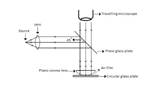 Figure Newton Ring Assembly
If monochromatic (means light with single wavelength) light is allowed to fall normally on the lens from a source 'S', then two reflected rays R1 (reflected from the upper surface of the film) and R2 (reflected from the lower surface of the air film) interfere to produce a circular interference pattern. This interference pattern has concentric alternate bright and dark rings around the point of contact. This pattern is observed through a traveling microscope.
Mathematical analysis of Newton’s Ring 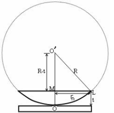 (OL)2 =(O’M)2-(ML)2 ……….(1) R2=(R-t)2 +rn2 R2=R2 +t2-2Rt +rn2 Radius is large as compared to the thickness So t2 is neglected as t2<< R2 R2=R2 +-2Rt +rn2 2Rt =rn2 Thickness of the film t =rn2 /2R……….(2)
Theory of Fringes: The effective path difference between the two reflected rays R1 and R2 for a wedge-shaped film from the equation ∆ = 2μtcos(r+θ) +λ/2……….(3) If the light is incident normally on the lens, r = 0 and near to point of contact θ is small; Therefore near the point of contact, (r+θ) approaches to 0 and cos(r+θ)=cos0=1 Therefore ∆ = 2μt+λ/2……….(4)
Also At the point of contact t = 0 therefore the effective path difference ∆ = λ/2 Which is an odd multiple of λ/2 Therefore the Central fringe is dark.
BRIGHT FRINGE: CONDITION OF MAXIMA For the condition of maxima the effective path difference ∆ = ±nλ Using equation (4) ∆ = 2μt+λ/2 we have 2μt+λ/2= ±nλ 2μt = ± (2n-1)λ /2……….(5)
DIAMETER OF BRIGHT RINGS We know by equation (2) t =rn2 /2R substitute in equation (5) we have 2μ (rn2 /2R) = ± (2n-1)λ /2 rn2 = ± (2n-1)λR /2μ We know diameter D=2r and for nth fringe Dn=2rn So we have Dn2=± 2(2n-1)λR /μ Dn=  The medium enclosed between the lens and glass plate is if air, therefore,  D=  The diameter of the bright ring is proportional to the square root of odd natural numbers
DARK FRINGE: CONDITION FOR MINIMA For the condition of minima, The effective path difference ∆ =± (2n+1)λ /2 2μt+λ/2 =± (2n+1)λ /2 2μt= ±nλ……….(7) It is clear that for particular dark or bright fringe t should be constant. Every fringe is the locus of points having equal thickness. Hence the fringes are circular.
DIAMETER OF DARK RINGS We know by equation (2) t =rn2 /2R substitute in equation (7) we have 2μ (rn2 /2R ) = nλ rn2 = nλR/ μ We know diameter D=2r and for nth fringe Dn=2rn So we have Dn2= 4nλR/ μ Dn=  The medium enclosed between the lens and glass plate is if air, therefore,  Dn=  The diameter of the dark ring is proportional to the square root of natural numbers. |
Q8) Newton’s rings are observed in the reflected light of wavelength 5900 Å. The diameter of the 10th dark ring is 0.5 cm. Find the radius of curvature of the lens used.
A8)
The given data are The wavelength of light (λ) = 5900 Å= 5900 × 10–10 m Diameter of 10th Newton’s dark ring (D10) = 0.5 cm = 0.5 × 10⁻² m The radius of curvature of the lens (R) =? Formula is D2n = 4nλR R= D2n /4nλ R= (0.5 × 10⁻²)2 /4x 10 x 5900 × 10–10 R= 0.25 x10⁻⁴ /236x10-7 R=1.059m |
Q9) Show that the fringe width of newton’s rings reduces with an increase in n.
Or
Show that the spacing of newton’s rings gets closer with an increase in n.
A9)
Spacing between Fringes The Newton’s rings are not equally spaced because the diameter of the ring does not increase in the same proportion as the order of ring and rings get closer and closer as ‘n’ increases. For example, the diameter of the dark ring is given by Dn=  D3 - D2 =       D7 – D6 =       D10– D9 =       From the above result, we conclude that the fringe width reduces with an increase in n. |
Q10) What happens when we use white light in newton’s rings method instead of monochromatic light?
A10)
Newton’s Ring with White Light If the monochromatic source is replaced by the white light, dark and bright fringes are not produced. Because the diameter of the rings depends upon wavelength and it is proportional to the square root of the wavelength. If the monochromatic source is replaced by the white light superposition of rings take place due to different wavelength. Few coloured rings are seen around the dark centre later illumination is seen in the field of view. As shown in the below figure. 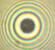 |
Q11) What do you mean by interference?
A11)
Interference in light waves occurs whenever two or more waves overlap at a given point.
TYPES OF INTERFERENCE
The interference of light waves can be either constructive interference or destructive interference.
- Constructive Interference: Constructive interference takes place when the crest of one wave falls on the crest of another wave such that the amplitude is maximum. These waves will have the same displacement and are in the same phase.
- Destructive Interference: In destructive interference, the crest of one wave falls on the trough of another wave such that the amplitude is minimum. The displacement and phase of these waves are not the same.
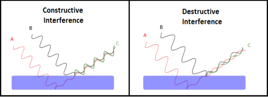 |
We know that the superposition of two mechanical waves can be constructive or destructive. In constructive interference, the amplitude of the resultant wave at a given position or time is greater than that of either individual wave, whereas, in destructive interference, the resultant amplitude is less than that of either individual wave.
Light waves also interfere with each other. Fundamentally, all interference associated with light waves arises when the electromagnetic fields that constitute the individual waves combine.
If two light bulbs are placed side by side, no interference effects are observed because the light waves from one bulb are emitted independently of those from the other bulb. The emissions from the two light bulbs do not maintain a constant phase relationship with each other over time. Light waves from an ordinary source such as a light bulb undergo random phase changes in time intervals less than a nanosecond.
Therefore, the conditions for constructive interference, destructive interference, or some intermediate state are maintained only for such short time intervals. Because the eye cannot follow such rapid changes, no interference effects are observed. Such light sources are said to be incoherent.
Q12) What are the conditions to obtain sustained interference of light?
A12)
In a sustained interference pattern, the position of maximum and minimum intensity regions remains constant with time. To obtain sustained interference, the following conditions are required:
- The sources must be coherent, that is, they must maintain a constant phase with respect to each other.
- The two light sources must emit continuous waves of the same wavelength and have the same period.
- The distance between the two sources of light must be small. This gives large fringe width so that the fringes are separately visible.
- The sources should be monochromatic, that is, of a single wavelength.
- The two light sources must emit waves in nearly the same direction.
- The light source must be a point source.
- The distance between the two sources and the screen must be large. This gives again large fringe width so that the fringes are separately visible.
Q13) Write a note on coherent sources?
A13)
Two sources are said to be coherent when the waves emitted from them have the same frequency and constant phase difference.
Interference from such waves happen all the time, the randomly phased light waves constantly produce bright and dark fringes at every point. But, we cannot see them since they occur randomly. A point that has a dark fringe at one moment may have a bright fringe at the next moment. This cancels out the effect of the interference effect, and we see only an average brightness value. The interference is not said to be sustained since we cannot observe it.
Definition:- A predictable correlation of the amplitude and phase at any one point with another point is called coherence.
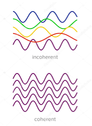 |
Two waves are said to be coherent, the waves must have
In the case of conventional light, the property of coherence exhibits between a source and its virtual source whereas in the case of laser the property coherence exists between any two or more light waves.
There are two types of coherence
i) Temporal coherence
Ii) Spatial coherence
TEMPORAL COHERENCE (OR LONGITUDINAL COHERENCE):-
The predictable correlation of amplitude and phase at one point on the wave train w .r. t another point on the same wave train, then the wave is said to be temporal coherence
To understand this, let us consider two points P1 and P2 on the same wave train, which is continuous as shown in the figure.
 |
Suppose the phase and amplitude at any one point is known, then we can easily calculate the amplitude and phase for any other point on the same wave train by using the wave equation
y= a sin ( (ct-x))
Where ‘a’ is the amplitude of the wave and ‘x’ is the displacement of the wave at any instant of time ‘t’.
SPATIAL COHERENCE (OR TRANSVERSE COHERENCE)
The predictable correlation of amplitude and phase at one point on the wave train w. r .t another point on a second wave, then the waves are said to be spatial coherence (or transverse coherence)
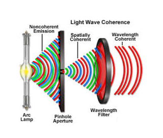 |
Q14) Explain Huygens' Principle?
A14)
Huygens' Principle In 1678 Huygens proposed a model where each point on a wavefront may be regarded as a source of waves expanding from that point. Every point on a wavefront is a source of wavelets that spread out in the forward direction at the same speed as the wave itself. The new wavefront is a line tangent to all of the wavelets. So Huygens’s Principle states that every point on a wavefront is a source of wavelets, which spread forward at the same speed. 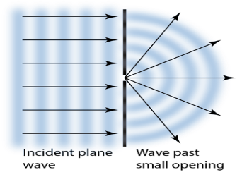
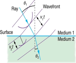
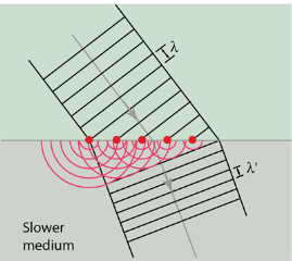
The expanding waves may be demonstrated in a ripple tank by sending plane waves toward a barrier with a small opening. If waves approaching a beach strike a barrier with a small opening, the waves may be seen to expand from the opening. Huygens-Fresnel Theory: According to Huygens’s wave theory of light, each progressive wave produces secondary waves, the envelope of which forms the secondary wavefront. In figure 11 (a). S is a source of monochromatic light and MN is a small aperture. XY is the screen placed in the path of light. AB is the illuminated portion of the screen and above A and below B is the region of the geometrical shadow. Considering MN as the primary wavefront. According to Huygens’s construction, if secondary wavefronts are drawn, one would expect encroachment of light in the geometrical shadow. Thus, the shadows formed by small obstacles are not sharp. This bending of light round the edges of an obstacle or the encroachment of light within the geometrical shadow is known as diffraction. Similarly, if an opaque obstacle MN is placed in the path of light [Figure 11 (b)], there should be illumination in the geometrical shadow region AB also. But the illumination in the geometrical shadow of an obstacle is not commonly observed because the light sources do not point sources and secondly the obstacles used are of very large size compared to the wavelength of light. If a shadow of an obstacle is cast by an extended source, say a frosted electric bulb, light from every point on the surface of the bulb forms its own diffraction pattern (bright and dark diffraction bands) and these overlap such that no single pattern can be identified. The term diffraction is referred to such problems in which one considers the resultant effect produced by a limited portion of a wavefront.  Huygens' principle provides a convenient way to visualize refraction. If points on the wavefront at the boundary of a different medium serve as sources for the propagating light, one can see why the direction of the light propagation changes. The law of refraction can be explained by applying Huygens’s principle to a wavefront passing from one medium to another (see Figure 12). Each wavelet in the figure was emitted when the wavefront crossed the interface between the media. Since the speed of light is smaller in the second medium, the waves do not travel as far in a given time, and the new wavefront changes direction as shown. This explains why a ray changes direction to become closer to the perpendicular when light slows down.
If we pass light through smaller openings, often called slits, we can use Huygens’s principle to see that light bends as sound does. The bending of a wave around the edges of an opening or an obstacle is called diffraction. Diffraction is a wave characteristic and occurs for all types of waves. If diffraction is observed for some phenomenon, it is evidence that the phenomenon is a wave. Thus the horizontal diffraction of the laser beam after it passes through slits is evidence that light is a wave. Diffraction phenomena are part of our common experience. The luminous border that surrounds the profile of a mountain just before the sun rises behind it, the light streaks that one sees while looking at a strong source of light with half-shut eyes and the colored spectra (arranged in the form of a cross) that one sees while viewing a distant source of light through a fine piece of cloth are all examples of diffraction effects. Augustine Jean Fresnel in 1815, combined strikingly Huygens' wavelets with the principle of interference and could satisfactorily explain the bending of light round obstacles and also the rectilinear propagation of light. |
Q15) A parallel beam of monochromatic light of wavelength 500nm is inclined normally on a plane diffraction grating 4000 per centimetre. Calculate the angle of diffraction for first-order principal maximum.
A15)
Given: number of lines per cm =4000 Grating element e+b = 1/4000 cm = 2.5 x 10⁻⁶m λ=500 nm Order n =1 (e+b) sinθ =nλ Sinθ = nλ / (e+b) Sinθ = 1 x 500 x 10-9 / 2.5 x 10⁻⁶ Sinθ =0.2 θ =sin-1 0.2 θ = 11.5o |
Q16) What are the Advantages and Disadvantages of Photoelasticity?
A16)
Advantages and Disadvantages
Advantages
- Photoelasticity, as used for two-dimensional plane problems,
- Provides reliable full-field values of the difference between the principal normal stresses in the plane of the model
- Provides uniquely the value of the non-vanishing principal normal stress along the perimeter(s) of the model, where stresses are generally the largest
- Furnishes full-field values of the principal-stress directions (sometimes called stress trajectories
- It is adaptable to both static and dynamic investigations
- Requires only a modest investment in equipment and materials for ordinary work
- It is fairly simple to use
Disadvantages
On the other hand, photo-elasticity
- Requires that a model of the actual part be made (unless photoelastic coatings are used)
- Requires rather tedious calculations in order to separate the values of principal stresses at a general interior point
- Can require expensive equipment for precise analysis of large components
- It is very tedious and time-consuming for three-dimensional work.
Q17) Write a note on diffraction grating?
A17)
A set of a large number of parallel slits of the same width and separated by opaque spaces is known as a diffraction grating. Diffraction gratings are much more effective than prisms for dispersing light of different wavelengths so they are used almost exclusively in instruments designed to detect and identify characteristic spectral lines. There is nothing mysterious about these devices. Fraunhofer used the first grating consisting of a large number of parallel wires placed side by side very closely at regular separation. Now the gratings are constructed by ruling the equidistance parallel lines on a transparent material such as glass with a fine diamond point. The ruled lines are opaque to light while the space between the two lines is transparent to light and acts as a slit. 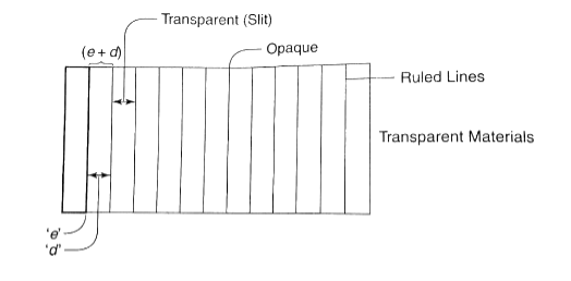
Let ‘e’ be the width of the line and ‘d’ be the width of the slit. Then (e + d) is known as the grating element. If N is the number of lines per inch on the grating then (𝑒+𝑑)=1𝑖𝑐ℎ=2.54𝑐𝑚 (𝑒+𝑑)=2.54𝑐𝑚/𝑁 Commercial gratings are produced by taking the cost of actual grating on a transparent film like that of cellulose acetate. The solution of cellulose acetate is poured on a ruled surface and allowed to dry to form a thin film, detachable from the surface. This film of the grating is kept between the two glass plates. |
Q18) A grating containing 4000 slits per centimetre is illuminated with a monochromatic light and produces the second-order bright line at a 30° angle. What is the wavelength of the light used? (1 Å = 10-10 m)
A18)
The distance between slits (d) = 1 / (4000 slits / cm) = 0.00025 cm = 2.5 x 10⁻⁴ cm = 2.5 x 10⁻⁶ meters Order (n) = 2 Sin 30o = 0.5 1 Å = 10-10 m Wavelength of the light (λ) =? 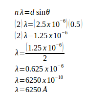 |
Q19) A monochromatic light with a wavelength of 2.5x10⁻⁷ m strikes a grating containing 10,000 slits/cm. Determine the angular positions of the second-order bright line.
A19)
Given The distance between slits (d) = 1 / (10,000 slits / cm) = 0.0001 cm = 1 x 10⁻⁴ cm = 1 x 10⁻⁶ m Order (n) = 2 Wavelength (λ) = 2.5 x 10⁻⁷ m Angle (θ) 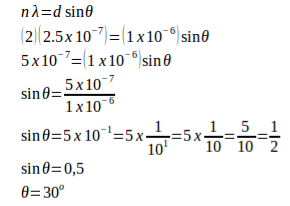
|
Q20) A monochromatic light with a wavelength of 500 nm (1 nm = 10-9 m) strikes a grating and produces the second-order bright line at a 30° angle. Determine the number of slits per centimetre.
A20) Wavelength (λ) = 500.10-9 m = 5.10-7 m θ = 30o n = 2 Distance between slits: d sin θ = n λ d (sin 30o) = (2)(5.10-7) d (0.5) = 10.10-7 d = (10.10-7) / 0.5 d = 20.10-7 d = 2.10-6 m Number of slits per centimetre: x = 1 / d x = 1 / 2.10-6 m x = 0.5.106 / 1 m x = 0.5.106 / 102 cm x = 0.5.104 cm x = 5.103 /cm x = 5000 /cm |
Q21) A monochromatic light with a wavelength of 500 nm (1 nano = 10-9) strikes a grating and produces the fourth-order bright line at a 30° angle. Determine the number of slits per centimetre.
A21)
Wavelength (λ) = 500.10-9 m = 5.10-7 m θ = 30o n = 4 Distance between slits: d sin θ = n λ d (sin 30o) = (4)(5.10-7) d (0.5) = 20.10-7 d = (20.10-7) / 0.5 d = 40.10-7 d = 4.10-6 m Number of slits per centimetre: x = 1 / 4.10-6 m x = 0.25.106 / m x = 0.25.106 / 102 cm x = 0.25.104 / cm x = 25.102 per cm x = 2500 per cm |
Q22) What is dispersive power for grating?
A22)
The dispersive power of a grating is defined as the ratio of the difference in the angle of diffraction of any two neighbouring spectral lines to the difference in the wavelength between the two spectral lines. Or It can also be defined as the diffraction in the angle of diffraction per unit change in wavelength. The diffraction of the nth order principal maximum for a wavelength λ is given by the equation, a + b is constant and n is constant in a given order. 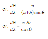 In equation (2) dθ/dλ is the dispersive power, n is the order of the spectrum, N’ is the number of lines per cm of the grating surface and θ is the angle of diffraction for the nth order principal maximum of wavelength λ. From equation (2), it is clear, that the dispersive power of the grating is directly proportional to the number of lines per cm and inversely proportional to cos θ. Thus, the angular spacing of any two spectral lines is double in the second-order spectrum in comparison to the first order. Secondly, the angular dispersion of the lines is more with a grating having a larger number of lines per cm. Thirdly, the angular dispersion is minimum when θ = 0. If the value of θ is not large the value of cosθ can be taken as unity approximately and the influence of the factor cosθ in the equation (2) can be neglected. Neglecting the influence of cosθ, it is clear that the angular dispersion of any two spectral lines (in a particular order) is directly proportional to the difference in wavelength between the two spectral lines. A spectrum of this type is called a normal spectrum. If the linear spacing of two spectral lines of wavelength λ and λ + dλ is dx in the focal plane of the telescope objective or the photographic plate, then, Dx = fdθ
 The linear dispersion is useful in studying the photographs of a spectrum. |
Q23) Derive expression for resolving power of grating?
A23)
It is defined as the capacity of a grating to form separate diffraction maxima of two wavelengths that are very close to each other It is measured by λ/dλ where dλ is the smallest difference in two wavelengths which are just resolvable by grating and λ is the wavelength of either of them or mean wavelength. 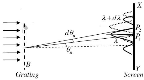
Let AB represent the surface of a plane transmission grating having grating element (e+d) and N total number of slits. Let a beam of light having two wavelengths by λ and dλ is normally incident on the grating. Let P1 is an nth primary maximum of a spectral line of wavelength λ at an angle of diffraction  According to the Rayleigh criterion, the two wavelengths will be resolved if the principal maximum λ+dλ of nth order in a direction θ+dθ falls over the first minimum of nth order in the same direction θ+dθ. Let us consider the first minimum of l of nth order in the direction θ+dθ as below. The principal maximum of  (e+d)sinθ =nλ ………………(1) The equation of minima is N(e+d)sinθ = mλ………………(2) Where m takes all integers except 0, N, 2N, …, nN, because for these values of m, the condition for maxima is satisfied. Thus first minimum adjacent to the nth principal maximum in the direction θ+dθ can be obtained by substituting the value of ‘m’ as (nN+1). Therefore, the first minimum in the direction of θ+dθ is given by N(e+d)sin(θ+dθ) = (nN+1)λ (e+d)sin(θ+dθ) = (n+  The principal maximum of λ+dλ in direction θ+dθ is given by (e+d)sin(θ+dθ) = n(λ+dλ) ………………(4) Dividing eqn(3) by equation (4), we get (n+  nλ +  
 Resolving Power =  Thus the resolving power is directly proportional to (i) The order of the spectrum ‘n’ (ii) The total number of lines on the grating ‘N’. |


