UNIT 3
SUPERCONDUCTIVITY AND MAGNETISM
Q1) What are the major differences between type I and Type II superconductor?
A1)
Differences between type I and Type II superconductor
Type I superconductor | Type II superconductor |
1. It follows the complete Meissner effect. | 1. It does not follow the complete Meissner effect |
2. It has a single critical field value HC | 2. It has two critical field values HC1 and HC2. |
3. There no mixed state. | 3. There is a mixed state |
4. They are soft superconductors | 4. They are hard superconductors |
5. Materials with pure form are type I superconductors | 5. Materials with impurities or alloys are type II superconductors |
Q2) Define superconductivity. Also, the discuss properties of superconductors?
A2)
Superconductivity
The ability of certain metals, their compounds, and alloys to conduct electricity with zero resistance at very low temperatures is called superconductivity. The materials which exhibit this property are called superconductors.
Properties
The following properties are shown by superconductors.
- It is a low-temperature phenomenon.
- The electrical resistivity drops to zero.
- The conductivity becomes infinity.
- The transition temperature is different for different substances.
- Material having high normal resistivity exhibit superconductivity.
- Materials for which ρZ= 106 (where Z is an atomic number and ρ is resistivity) show superconductivity.
- Superconductivity is very sharp for the chemically pure and structurally perfect specimen.
- Ferromagnetic and Antiferromagnetic materials are not superconductors.
- Below the transition temperature, the magnetic flux lines are rejected out of the superconductors.
- Generally, Superconducting elements lie in the inner columns of the periodic table.
- Those metallic elements having their valence electrons lies between 2 to 8 exhibit superconductivity.
- Below the transition temperature, the specific heat curve is discontinuous.
- There is a discontinuous change in specific heat.
- There are small changes in the volume and thermal conductivity of the material.
Q3) The critical field for niobium is 1 × 10⁵ amp/m at 8 K and 2 × 10⁵ amp/m at absolute zero. Find the transition temperature of the element.
A3)
Critical magnetic field at 8 K, HC = 1 × 10⁵ amp/m T = 8 K Critical magnetic field at 0 K, H0 = 2 × 10⁵ amp/m Transition temperature, TC =? HC(T) = HC(0) [ 1 – (T/TC)2] HC(T)/ HC(0) = 1 – (T/TC)2 (T/TC)2 = 1-(HC(T)/ HC(0)) Tc2 = T2 /1- (HC(T)/ HC(0)) Tc2 = 82 /1-(1 × 105 /2 × 105) Tc2 = 82 /1-(1 /2) Tc2 = 82 /(1/2) Tc = 8 x  Tc = 11.3 K
|
Q4) Describe briefly the Meissner effect in a superconductor.
A4)
The Meissner effect In 1933, Walter Meissner and Robert Ochsenfeld discovered a magnetic phenomenon that showed that superconductors are not just perfect conductors. When a weak magnetic is applied to a superconducting specimen at a temperature below transition temperature Tc the magnetic flux lines are expelled. This phenomenon is called the Meissner effect.
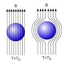 Figure 1 Under normal state the magnetic induction inside the specimen is B = μ0(H+I) Where H is the external applied magnetic field and I is the magnetization produced inside the specimen. When the specimen is in superconducting state B=0 (Meissner effect) B = μ0(H+I) 0 = μ0(H+I) H= -I χ = H/I =-1 Thus the material is act as a perfectly diamagnetic because for diamagnetic material susceptibility χ = -1 . Let us consider a superconducting material is in a normal state. From ohms law, the electric field E=Jρ On cooling the material to its transition temperature ρ tends to zero. If J is held finite E must be zero. From Maxwell’s equations ∇ × E = - dB / dt Under superconducting condition Since E is zero DB/dt =0 Or B=constant. This means that the magnetic flux passing through the specimen should not change on cooling to the transition temperature. The Meissner effect contradicts the result. |
Q5) A superconducting tin has a critical temperature of 3.7 K at zero magnetic fields and a critical field of 0.0306 Tesla at 0 K. Find the critical field at 2 K.
A5)
Critical magnetic field at 0 K, H0 = 0.0306 Tesla T = 2 K Transition temperature, TC =3.7 K The critical magnetic field at 2 K, Hc =? HC(T) = HC(0) [ 1 – (T/TC)2] HC(T) = 0.0306 [ 1 – (2/3.7)2] HC(T) = 0.0216 Tesla
|
Q6) Define Magnetic susceptibility (χ)
A6)
If H is the applied magnetizing field intensity and M is the amount of magnetization of the material, Then χ =  χ = 0 in vacuum χ = +ve for paramagnetic and Ferro magnetic materials χ = -ve for diamagnetic materials Units: It has no units. |
Q7) How can we Classify Magnetic Materials?
A7)
Magnetic materials are classified as follows:
- Diamagnetic
- Paramagnetic
- Ferromagnetic
- Anti-Ferro magnetic
- Ferric magnetic or ferrites
Diamagnetic
The orbital motion of electrons around the nucleus produces a magnetic field perpendicular to the plane of the orbit. Thus each electron orbit has a finite orbital magnetic dipole moment. Since the orbital planes are oriented randomly, the vector sum of magnetic moments is zero and there is no resultant magnetic moment for each atom.
In the presence of an external magnetic field, some electrons are speeded up and some are slowed down. The electrons whose moments were anti-parallel are speeded up according to Lenz’s law and this produces an induced magnetic moment in a direction opposite to the field. The induced moment disappears as soon as the external field is removed.
When placed in a non-uniform magnetic field, the interaction between the induced magnetic moment and the external field creates a force that tends to move the material from the stronger part to the weaker part of the external field. It means that diamagnetic material is repelled by the field.
This action is called diamagnetic action and such materials are known as diamagnetic materials. Examples: Bismuth, Copper, and Water, etc.
The properties of diamagnetic materials are
- Magnetic susceptibility is negative.
- Relative permeability is slightly less than unity.
- The magnetic field lines are repelled or expelled by diamagnetic materials when placed in a magnetic field.
- Susceptibility is nearly temperature independent.
- Examples: Cu, Au, Zn, H20, Bi, etc. organic materials
Paramagnetic materials
In some magnetic materials, each atom or molecule has a net magnetic dipole moment which is the vector sum of orbital and spin magnetic moments of electrons. Due to the random orientation of these magnetic moments, the net magnetic moment of the materials is zero.
In the presence of an external magnetic field, the torque acting on the atomic dipoles will align them in the field direction. As a result, there is a net magnetic dipole moment induced in the direction of the applied field. The induced dipole moment is present as long as the external field exists.
The properties of paramagnetic materials are:
- Magnetic susceptibility is positive and small.
- Relative permeability is greater than unity.
- The magnetic field lines are attracted to the paramagnetic materials when placed in a magnetic field.
- Susceptibility is inversely proportional to temperature.
Ferromagnetic materials
An atom or a molecule in a ferromagnetic material possesses a net magnetic dipole moment as in a paramagnetic material. A ferromagnetic material is made up of smaller regions, called ferromagnetic domain. Within each domain, the magnetic moments are spontaneously aligned in a direction. This alignment is caused by strong interaction arising from electron spin which depends on the inter-atomic distance. Each domain has net magnetization in a direction. However, the direction of magnetisation varies from domain to domain and thus net magnetisation of the specimen is zero.
In the presence of an external magnetic field, two processes take place
1. The domains having magnetic moments parallel to the field grow in size
2. The other domains (not parallel to the field) are rotated so that they are aligned with the field.
As a result of these mechanisms, there is a strong net magnetisation of the material in the direction of the applied field
When placed in a non-uniform magnetic field, the ferromagnetic materials will have a strong tendency to move from the weaker to the stronger part of the field. Materials that exhibit strong magnetism in the direction of the applied field are called ferromagnetic materials. Examples: Iron, Nickel, and Cobalt.
The properties of ferromagnetic materials are:
- Magnetic susceptibility is positive and large.
- Relative permeability is large.
- The magnetic field lines are strongly attracted to the ferromagnetic materials when placed in a magnetic field.
- Susceptibility is inversely proportional to temperature.
Antiferromagnetism
In the periodic table, the only element exhibiting antiferromagnetism at room temperature is chromium. Antiferromagnetic materials are very similar to ferromagnetic materials but the exchange interaction between neighboring atoms leads to the anti-parallel alignment of the atomic magnetic moments. Therefore, the magnetic field cancels out and the material appears to behave in the same way as a paramagnetic material. Like ferromagnetic materials, these materials become paramagnetic above a transition temperature, known as the Neel temperature, TN. (Cr: TN=37ºC).
The properties of antiferromagnetic materials are:
- They have permanent magnetic dipoles
- They do not possess a permanent magnetic dipole moment. Since in the absence of field, they have no spontaneous magnetization due to anti-parallel spin
- The relative permeability μr>1
- Susceptibility χ is small but negative
- 𝜒depends on temperature
Ferrimagnetism
Ferrimagnetism is only observed in compounds, which have more complex crystal structures than pure elements. Within these materials, the exchange interactions lead to parallel alignment of atoms in some of the crystal sites and anti-parallel alignment of others. The material breaks down into magnetic domains, just like a ferromagnetic material and the magnetic behaviour is also very similar, although ferrimagnetic materials usually have lower saturation magnetisations. For example in Barium ferrite (BaO.6Fe2O3) the unit cell contains 64 ions of which the barium and oxygen ions have no magnetic moment, 16 Fe3+ ions have moments aligned parallel, and 8 Fe3+ aligned anti-parallel giving a net magnetisation parallel to the applied field, but with a relatively low magnitude as the only ⅛ of the ions contribute to the magnetisation of the material.
The properties of ferrimagnetic materials are:
- They have permanent magnetic dipoles.
- They possess a permanent magnetic dipole moment. Also in the absence of field, they have spontaneous magnetization. Since spin is anti-parallel but of different magnitudes
- The relative permeability μr>>1
- Susceptibility is large and positive
- 𝜒 depends on the temperature
Q8) What do you mean by zero resistivity?
A8)
The most obvious characteristic of a superconductor is the complete disappearance of its electrical resistance below a temperature that is known as its critical temperature.
In a superconductor, below a temperature called the “critical temperature”, the electric resistance very suddenly falls to zero. At zero resistance, the material conducts current perfectly. This is incomprehensible because the flaws and vibrations of the atoms should cause resistance in the material when the electrons flow through it. However, in a superconductor, the electric resistance is equal to zero although the flaws and vibrations still exist.
Experiments have been carried out to attempt to detect whether there is any small residual resistance in the superconducting state. A sensitive test is to start a current flowing round a superconducting ring and observe whether the current decays.
The current flowing in the superconducting loop clearly cannot be measured by inserting an ammeter into the loop, since this would introduce resistance and the current would rapidly decay.
The magnitude of the magnetic field is directly proportional to the current circulating in the loop, and the field can be measured without drawing energy from the circuit. Experiments of this type have been carried out over periods of years, and the magnetic field – and hence the superconducting current – has always remained constant within the precision of the measuring equipment. Such a persistent current is characteristic of the superconducting state.
The resistance is equal to zero. The measurements taken over the course of several years show that the current never decreases. Even though the current is perpetual, it is not a violation of the thermodynamic laws (which forbids perpetual motion machines), because in this case no energy is created. The electric and magnetic energy is merely stored in the ring.
From the lack of any decay of the current, it has been deduced that the resistivity ρ of a superconductor is less than 10−26 Ω m. This is about 18 orders of magnitude smaller than the resistivity of copper at room temperature ( 10−8 Ω m).
Resistivity is the reciprocal of conductivity, that is, ρ = σ−1. We prefer to describe a superconductor by ρ = 0, rather than by σ =  .
.
Critical Temperature for Superconductors
The critical temperature for superconductors is the temperature at which the electrical resistivity of metal drops to zero. The transition is so sudden and complete that it appears to be a transition to a different phase of matter; this superconducting phase is described by the BCS theory. Several materials exhibit superconducting phase transitions at low temperatures. The highest critical temperature was about 23 K until the discovery in 1986 of some high-temperature superconductors.
Materials with critical temperatures in the range 120 K have received a great deal of attention because they can be maintained in the superconducting state with liquid nitrogen (77 K).
Q9) Discuss in brief the B-H curve?
A9)
Magnetic Hysteresis
The lag or delay of a magnetic material known commonly as Magnetic Hysteresis relates to the magnetization properties of a material by which it first becomes magnetized and then de-magnetized.
The set of magnetization curves, M above represents an example of the relationship between B and H for soft-iron and steel cores but every type of core material will have its own set of magnetic hysteresis curves. You may notice that the flux density increases in proportion to the field strength until it reaches a certain value where it cannot increase any more becoming almost level and constant as the field strength continues to increase.
This is because there is a limit to the amount of flux density that can be generated by the core as all the domains in the iron are perfectly aligned. Any further increase will not affect the value of M, and the point on the graph where the flux density reaches its limit is called Magnetic Saturation also known as Saturation of the Core and in our simple example above the saturation point of the steel, the curve begins at about 3000 ampere-turns per metre.
As the magnetic field strength, ( H ) increases these molecular magnets become more and more aligned until they reach perfect alignment producing maximum flux density, and an increase in the magnetic field strength due to an increase in the electrical current flowing through the coil will have little or no effect.
Retentivity
Let’s assume that we have an electromagnetic coil with a high field strength due to the current flowing through it and that the ferromagnetic core material has reached its saturation point, maximum flux density. If we now open a switch and remove the magnetizing current flowing through the coil we would expect the magnetic field around the coil to disappear as the magnetic flux reduced to zero.
However, the magnetic flux does not completely disappear as the electromagnetic core material still retains some of its magnetism even when the current has stopped flowing in the coil. This ability for a coil to retain some of its magnetism within the core after the magnetization process has stopped is called Retentivity or remanence, while the amount of flux density remaining in the core is called Residual Magnetism, BR.
The reason for this that some of the tiny molecular magnets do not return to a completely random pattern and still point in the direction of the original magnetizing field giving them a sort of “memory”. Some ferromagnetic materials have a high retentivity (magnetically hard) making them excellent for producing permanent magnets.
While other ferromagnetic materials have low retentivity (magnetically soft) making them ideal for use in electromagnets, solenoids, or relays. One way to reduce this residual flux density to zero is by reversing the direction of the current flowing through the coil, thereby making the value of H, the magnetic field strength negative. This effect is called a Coercive Force, HC.
If this reverse current is increased further the flux density will also increase in the reverse direction until the ferromagnetic core reaches saturation again but in the reverse direction from before. Reducing the magnetizing current, i once again to zero will produce a similar amount of residual magnetism but in the reverse direction.
Then by constantly changing the direction of the magnetizing current through the coil from a positive direction to a negative direction, as would be the case in an AC supply, a Magnetic Hysteresis loop of the ferromagnetic core can be produced.
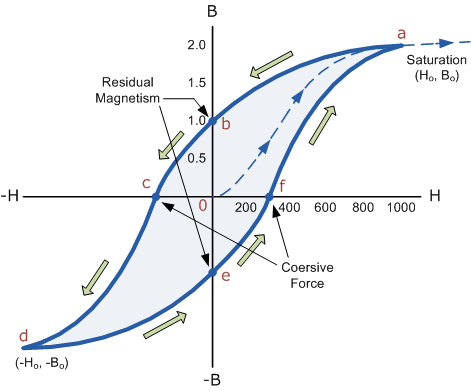 |
Figure 2
The B-H Curve or Magnetic Hysteresis loop above shows the behaviour of a ferromagnetic core graphically as the relationship between B and H is non-linear.
Starting with an unmagnetized core both B and H will be at zero, point 0 on the magnetization curve.
If the magnetization current, i is increased in a positive direction to some value the magnetic field strength H increases linearly with i and the flux density B will also increase as shown by the curve from point 0 to point a as it heads towards saturation.
Now if the magnetizing current in the coil is reduced to zero, the magnetic field circulating around the core also reduces to zero. However, the coils magnetic flux will not reach zero due to the residual magnetism present within the core and this is shown on the curve from point a to point b.
To reduce the flux density at point b to zero we need to reverse the current flowing through the coil. The magnetising force which must be applied to null the residual flux density is called a “Coercive Force”. This coercive force reverses the magnetic field re-arranging the molecular magnets until the core becomes unmagnetised at point c.
An increase in this reverse current causes the core to be magnetised in the opposite direction and increasing this magnetisation current further will cause the core to reach its saturation point but in the opposite direction, point d on the curve.
This point is symmetrical to point b. If the magnetising current is reduced again to zero the residual magnetism present in the core will be equal to the previous value but in reverse at point e.
Again reversing the magnetising current flowing through the coil this time into a positive direction will cause the magnetic flux to reach zero, point f on the curve and as before increasing the magnetisation current further in a positive direction will cause the core to reach saturation at point a.
Then the B-H curve follows the path of a-b-c-d-e-f-a as the magnetising current flowing through the coil alternates between a positive and negative value such as the cycle of an AC voltage. This path is called a B-H Curve or Magnetic Hysteresis Loop.
The effect of magnetic hysteresis shows that the magnetisation process of a ferromagnetic core and therefore the flux density depends on which part of the curve the ferromagnetic core is magnetised on as this depends upon the circuits past history giving the core a form of “memory”. Then ferromagnetic materials have memory because they remain magnetised after the external magnetic field has been removed.
However, soft ferromagnetic materials such as iron or silicon steel have very narrow magnetic hysteresis loops resulting in very small amounts of residual magnetism making them ideal for use in relays, solenoids, and transformers as they can be easily magnetised and demagnetised.
Since a coercive force must be applied to overcome this residual magnetism, work must be done in closing the hysteresis loop with the energy being used being dissipated as heat in the magnetic material. This heat is known as hysteresis loss, the amount of loss depends on the material’s value of coercive force.
By adding additives to the iron metal such as silicon, materials with a very small coercive force can be made that have a very narrow hysteresis loop. Materials with narrow hysteresis loops are easily magnetised and demagnetised and known as soft magnetic materials.
Q10) Draw B-H Curve for Soft and Hard Materials?
A10)
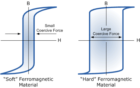 |
Figure 3
The shape of the hysteresis loop depends upon the nature of the iron or steel used and in the case of iron which is subjected to massive reversals of magnetism, for example, transformer cores, the B-H hysteresis loop must be as small as possible.
Q11) What is the isotope effect?
A11)
ISOTOPE EFFECT It has been observed that the critical temperature of superconductors varies with isotopic mass. In mercury Tc, varies from 4.185 K to 4.146 K as the average atomic mass varies from 199.5 to 203.4 atomic mass units. The transition temperature changes smoothly when we mix different isotopes of the same element. The experimental results within each series of isotopes may be befitted by a relation of the form Mα TC = constant……………(1) In superconducting materials, the transition temperature varies with the average isotopic mass of their constituents. The variation is found to be in general form TC ∝ M−α Or TC Mα= constant Where α is the isotopic effect coefficient and is defined as α = ∂ ln TC /∂ ln M As already discussed the value of α is approximately 0.5. For example, the average mass varies from 199.5 to 203.4 atomic mass units, and accordingly, the transition temperature varies from 4.185K to 4.146K. From the dependence of Tc, on the isotopic mass, we learn that lattice vibrations and hence electron-lattice interactions arc deeply involved in superconductivity This was a fundamental discovery: there is no other reason for the superconducting transition temperature to depend on the number of neutrons in the nucleus The original BCS model gave the result Tc    
|
Q12) Explain BCS theory?
A12)
BCS THEORY
BCS theory of superconductor was put forward by Bardeen, Cooper, and Schrieffer in 1957 and hence named as BCS theory. This theory could explain the effects such as zero resistivity, Meissner effect, isotopic effect, etc. Electron lattice interaction via lattice deformation.
Electron-phonon Interaction
BCS theory showed that the basic interaction responsible for superconductivity appears to be that of a pair of electrons by means of an interchange of virtual phonons. This is explained as follows:-
Suppose an electron approaches a positive ion core. It suffers attractive Coulomb interaction. Due to this attraction ion core is set in motion and thus distorts that lattice. Let a second electron come in the way of distorted lattice and interaction between the two occurs which lowers the energy of the second electron. The two electrons, therefore, interact indirectly, via lattice distortion or the phonon field, thus lowering the energy of electrons. This type of interaction is called electron-lattice is quantized in terms of phonons the above interaction can also be interpreted as electron-electron interaction through phonons.
Let an electron of wave vector K emits phonon q, which is absorbed by an electron of wave number K. K is thus scattered as K-q and the process being a virtual one. The nature of the resulting electron-electron interactions depends on the relative magnitudes of the electronic energy change and the phonon energy. If this phonon energy exceeds electronic energy, the interaction is attractive.
Let us consider an electron is passing through the lattice positive ions. The electron is attracted by the neighboring lattice positive ions as shown in figure 9. Due to the attraction of electron and ion core, the lattice gets deformed on the scale. So electrons get a partially positive charge. Now if another electron passes by the side of the assembly of said electron and ion core, it gets attracted towards the assembly.
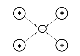 |
Figure 4
The second electron interacts with the first electron due to the exchange of virtual photon q, between two electrons. The interaction process can be written in terms of the wave vector k as
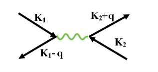 |
Figure 5
k1’ =k1–q k2’ = k2+q
These two electrons together form a cooper pair and are known as cooper electrons.
Cooper pairs
To understand the mechanism of cooper pair formation, let us consider the distribution of electrons in metals as given by the Fermi-Dirac distribution function.
F(E) = 1/ 1+ e E-EF/kT
At T= 0K, all the Fermi energy states below the Fermi level are filled and all the states above are empty. Let us see what happens when two electrons are added to metal at absolute zero. Since all the quantum states E<EF, are filled, they are forced to occupy states having E>EF.
Cooper showed that if there an attraction between the two electrons, they can form a bound state so that their total energy is less than 2EF. These two electrons are paired to form a single system. These two electrons form a cooper pair and are known as cooper electrons.
Coherence length
The paired electrons are not scattered and can maintain their coupled motion up to a certain distance called the coherence length. It is a measure of the distance within which the gap parameter does not change very much in a varying magnetic field.
Q13) Write applications of a superconductor?
A13)
Applications of superconductor
- Superconductors form the basis of energy-saving power systems, namely the superconducting generators, which are smaller in size and weight, in comparison with conventional generators.
- Superconducting magnetic propulsion systems may be used to launch satellites into orbits directly from the earth without the use of rockets.
- High-efficiency ore-separating machines may be built using superconducting magnets which can be used to separate tumour cells from healthy cells by the high gradient magnetic separation method.
- Since the current in a superconducting wire can flow without any change in magnitude, it can be used for transmission lines.
- Superconductors can be used as memory or storage elements in computers.
- If you set up a current in a loop of superconductor there is nothing to stop it and it will continue flowing forever, forming a very powerful electromagnet, that needs no maintenance other than keeping them cold. The strongest man-made permanent magnetic fields are produced using superconductors.
- Superconducting magnets are used in MRI (Magnetic Resonance Imaging) which is a way of looking at the soft parts of the body.
- They are also going to be used in the new ‘Large Hadron Collider’ experiment at the CERN Particle Physics Lab. The idea is to accelerate protons and antiprotons to almost the speed of light in a circle and then smash them together. To keep the particles in a circle requires huge magnetic fields which can only be provided by superconductors.
- It is also possible to use superconducting magnets to produce a levitating train. The idea is to put very powerful light superconducting magnets on the train, then use copper coils in the track which use repulsion to lift the train to make it levitate. It is also possible to use the track magnets to push the train along. Because this force is not limited by friction between wheels and a track it is theoretically possible for a maglev train to go much faster and more importantly accelerate and brake faster than a conventional train. Various test maglev trains have been built, in Birmingham, Japan, and Germany, although the only one used commercially is a german design built-in Shanghai, which uses very strong permanent magnets instead of superconductors.
- Due to the subtlety of the quantum mechanics of how superconductors interact with magnetic fields, it is possible to make the most sensitive magnetometers possible called SQUIDs (Superconducting Quantum Interference Devices). These can be used to detect submarines, measure the magnetic field produced by your brain, find ore deposits deep underground, sense minute signals from stars, etc.
- An obvious use of superconductors would be to move power around, huge amounts of electrical energy are wasted just heating power cables, and superconductors would help. However, if you put alternating current through them they are no longer lossless, and it requires a lot of energy to cool them, so although it is possible they could be used to save energy in the long run in the short term it is more likely they will be used to save space, superconducting cables have been installed in Chicago and Copenhagen, in old cable ducts with restricted space, allowing you to get more power through the same duct, hence saving lots of money digging up the road. Similarly, the US Navy is very interested in them making small powerful electric motors to power ships with, because it is efficient to put the propellers on pods under the ship however the bigger the motor the more drag it produces, so a much smaller superconducting motor would be advantageous.
Q14) Discuss DC Josephson Effect?
A14)
Josephson Effect Let us consider a thin insulation layer is sandwiched between the two superconductors in addition to normal tunneling of electrons, the super electrons tunnel through the insulation layer from one superconductor to another with dissociation, even at zero potential difference across the junction. Their wave functions on both sides are highly correlated. This is known as the Josephson Effect.
D.C Josephson effect According to Josephson when tunneling across through the insulator it introduces a phase difference ϕ0 between the two parts of the function on opposite sides of the junction as shown in figure 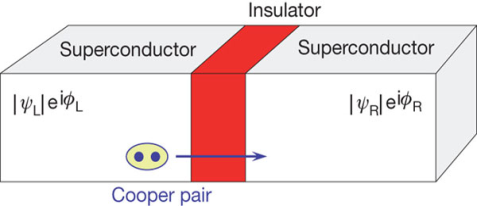 Figure 6 The tunneling current is given by I =I0 Sin(ϕ0) Where I0 is the maximum current that flows through the junction without any potential difference across the junction. This effect is called the D.C Josephson effect. Mathematical Analysis 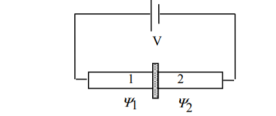 Figure 7: Two superconductors separated by a thin insulator Suppose we have two superconductors connected by a thin layer of insulating material as shown in the figure. We define Ψ1 and Ψ2 as the quantum mechanical wave function of the superconducting state in the left and the right superconductor. The dynamics of the two wave functions are then determined by the following coupled Schrödinger equations:
iℏ  iℏ  Where K is constant representing the coupling across the barrier. And µ1, µ2 are the lowest energy states on either side. The wavefunctions can be written as Ψ1 =   Ψ2 =   Where n1, n2 is the density of Cooper pairs and θ are the phases. Substituting equation (2) into equation (1) gives
ℏ    ℏ  The time derivative of the density of Cooper pairs describes a charge transport therefore I = ∂n1/∂t. If a voltage V is applied between the junctions the energy levels will shift that is µ2 −µ1 = 2eV. Let I0 = 2K (n1n2) ½/ ℏ and ϕ0= θ1 – θ2 then I =I0 Sin ϕ0…….(5)  Equations (5) and (6) provide the main results of Josephson junction theory. The current I is called a Josephson current or a supercurrent. This strongly predicts non-linear current-voltage behavior. From equation (5,6) it is clear that a DC can be drawn through the junction without any voltage drop, as long as the DC is smaller than I0. The phase difference will adjust according to equation (5). |
Q15) Explain the AC Josephson Effect and its applications?
A15)
A.C Josephson effect Let a static potential difference is applied across the junction, an additional phase is introduced by the cooper pairs during tunneling across the junction. This additional phase change ∆ϕ at any time t can be calculated using quantum mechanics.  Figure 8 ∆ϕ = Et /ℏ Where E denotes the total energy of the system. In present case E=2eV0 Hence ∆ϕ = 2eV0t /ℏ The tunneling current can be written as I = I0 Sin(ϕ0 +2eV0t /ℏ) I = I0 Sin(ϕ0 +ωt ) Where ω = 2eV0/ℏ This represents alternating current with angular frequency ω. This is the A.C Josephson effect. The current-voltage characteristic of a junction is shown in the figure.
Figure 9 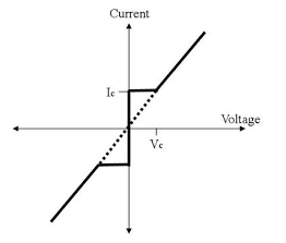 When Vo = 0 there is a constant flow of DC through the junction. This current is called superconducting current and the effect is called the Josephson effect. When Vo < Vc, a constant DC Ic flows. When Vo > Vc, the junction has finite resistance, and the current oscillates with some frequency. Applications of Josephson Effect
|
Q16) Explain SQUID?
A16)
The sensitivity of the Josephson current to very fine changes in the flux is used to build something called a Superconducting Quantum Interference Device (SQUID). A two-junction SQUID is depicted in the figure.
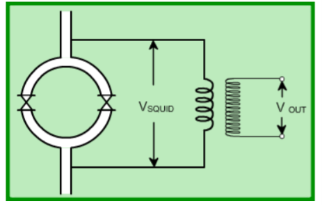 Figure 10
The superconducting quantum interference device (SQUID) consists of two superconductors separated by thin insulating layers to form two parallel Josephson junctions. Here, a current change through the weak links (due to a field change in the loop) is converted to a voltage change which is further amplified using a step-up transformer and amplifiers. This is called a dc SQUID. There is another variety of SQUID called an rf SQUID. In this, there is one weak link (Josephson junction). An LC-tuned circuit driven by an rf current source is coupled to the SQUID (see figure). 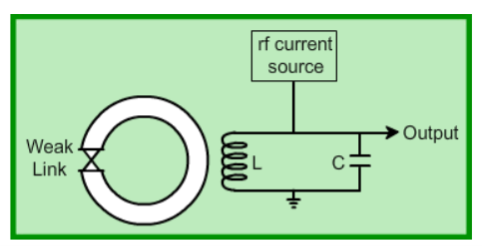 Figure 11 A change in the flux threading the loop produces a change in the loading of the tuned LC circuit. This gives rise to a change in the rf voltage across the circuit which is then detected. The device may be configured as a magnetometer to detect incredibly small magnetic fields small enough to measure the magnetic fields in living organisms. Squids have been used to measure the magnetic fields in mouse brains to test whether there might be enough magnetism to attribute their navigational ability to an internal compass.
The great sensitivity of the SQUID devices is associated with measuring changes in the magnetic field associated with one flux quantum. One of the discoveries associated with Josephson junctions was that flux is quantized in units  If a constant biasing current is maintained in the SQUID device, the measured voltage oscillates with the changes in phase at the two junctions, which depends upon the change in the magnetic flux. Counting the oscillations allows you to evaluate the flux change which has occurred. With the ability to detect small magnetic moments, immediate use of SQUIDs is to incorporate it in devices to measure magnetic moments as a function of temperature and field. These are called magnetometers. Incidentally, the magnets used in magnetometers (to generate an externally applied field) are often solenoidal magnets made of superconductors. As a consequence, fields up to 9 Tesla are routinely available in commercial machines. Another widespread application of SQUIDs is the detection of magnetic fields produced by living organisms. In particular, brain functions are studied by mapping the magnetic fields produced by neural currents in the human brain. This is possible using SQUIDs since they can detect flux changes better than one flux quantum. |
Q17) Explain magnetic domain?
A17)
This magnetic domain theory for ferromagnetic was first proposed by Pierre-Ernest Weiss in 1906. The microscopic ordering of electron spins characteristic of ferromagnetic materials leads to the formation of regions of magnetic alignment called domains.
The magnetic moments of atoms dictate the magnetic properties of a material. In ferromagnetic materials, long-range alignments of magnetic moments, called domains, contain magnetic moments that all point in the same direction.
However, if material were to have all of its magnetic moments pointed in the same direction, this would create a very large external magnetic field. This field is not energetically minimizing as it stores large amounts of magnetostatic energy in the field.
Thus, for the system to minimize its internal energy, it must minimize the external field produced. To do this, the material creates different domains within itself to redirect the magnetic field. The regions in-between these domains are known as domain walls.
Interactions of a material's exchange interaction, magnetocrystalline anisotropy, and minimization of external magnetic field determine the domain structure of a material.
The magnetisation within the domain is saturated and will always lie in the easy direction of magnetisation when there is no externally applied field. The direction of the domain alignment across a large volume of material is more or less random and hence the magnetisation of a specimen can be zero.
Magnetic domains exist in order to reduce the energy of the system. A uniformly magnetised specimen as shown in figure 17(a) has large magnetostatic energy associated with it. This is the result of the presence of magnetic free poles at the surface of the specimen generating a demagnetising field, Hd. From the convention adopted for the definition of the magnetic moment for a magnetic dipole the magnetisation within the specimen points from the south pole to the north pole, while the direction of the magnetic field points from north to south. Therefore, the demagnetising field is in opposition to the magnetisation of the specimen. The magnitude of Hd is dependent on the geometry and magnetisation of the specimen.
In general, if the sample has a high length to diameter ratio (and is magnetised in the long axis) then the demagnetising field and the magnetostatic energy will be low.
The break-up of the magnetisation into two domains as illustrated in figure 17(b) reduces the magnetostatic energy by half. In fact, if the magnet breaks down into N domains then the magnetostatic energy is reduced by a factor of 1/N, hence figure17(c) has a quarter of the magnetostatic energy of figure 17(a). Figure 17(d) shows a closure domain structure where the magnetostatic energy is zero, however, this is only possible for materials that do not have a strong uniaxial anisotropy, and the neighbouring domains do not have to be at 180º to each other.
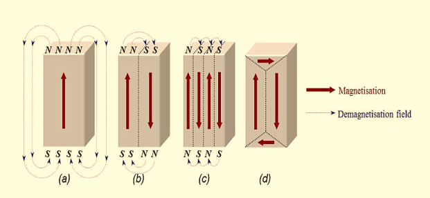 |
Figure 12: Schematic illustration of the break-up of magnetisation into domains: (a) single domain; (b) two domains; (c) four domains; (d) closure domains.
The introduction of a domain raises the overall energy of the system, therefore the division into domains only continues while the reduction in magnetostatic energy is greater than the energy required to form the domain wall.
The energy associated with a domain wall is proportional to its area. The schematic representation of the domain wall, shown in figure 18, illustrates that the dipole moments of the atoms within the wall are not pointing in the easy direction of magnetisation and hence are in a higher energy state.
In addition, the atomic dipoles within the wall are not at 180º to each other and so the exchange energy is also raised within the wall. Therefore, the domain wall energy is an intrinsic property of a material depending on the degree of magnetocrystalline anisotropy and the strength of the exchange interaction between neighbouring atoms. The thickness of the wall will also vary in relation to these parameters, as a strong magnetocrystalline anisotropy will favour a narrow wall, whereas a strong exchange interaction will favour a wider wall.
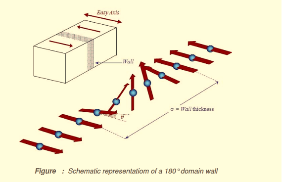 |
Figure 13
Minimum energy can therefore be achieved with a specific number of domains within a specimen. This number of domains will depend on the size and shape of the sample (which will affect the magnetostatic energy) and the intrinsic magnetic properties of the material (which will affect the magnetostatic energy and the domain wall energy).
The main implication of the domains is that there is already a high degree of magnetization in ferromagnetic materials within individual domains, but that in the absence of external magnetic fields those domains are randomly oriented. A modest applied magnetic field can cause a larger degree of alignment of the magnetic moments with the external field, giving a large multiplication of the applied field.
These illustrations of domains are conceptual only and not meant to give an accurate scale of the size or shape of domains.
The microscopic evidence about magnetization indicates that the net magnetization of ferromagnetic materials in response to an external magnetic field may actually occur more by the growth of the domains parallel to the applied field at the expense of other domains rather than the reorientation of the domains themselves as implied in the sketch.

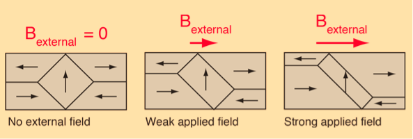 |
Figure 14
The internal magnetic fields which come from the long-range ordering of the electron spins are much stronger, sometimes hundreds of times stronger, than the external magnetic fields required to produce these changes in domain alignment.