UNIT 5
Design Basics, Machine And Mechanisms
Question 1) writes safety precautions of lathe?
Answer 1) as always we should be aware of safety requirements and attempt to observe safety rules in order to eliminate serious injury to ourselves or others.
Wear glasses, short sleeves, no tie, no rings, no trying to stop the work by hand. Stop the machine before trying to check the work. Don’t know how it works? –“Don’t run it.” Don’t use rags when the machine is running.
1. Remove the chuck key from the chuck immediately after use. Do not turn the lathe on if the chuck is still in the chuck key.
2. Turn the chuck or faceplate through by hand unless there are binding or clearance issues.
3. It is important that the chuck or faceplate is securely tightened onto the lathe’s spindle.
4. Move the tool bit to a safe distance from the chuck, collet, or face plate when inserting or removing your part.
5. Place the tool post holder to the left of the compound slide. This will ensure that the compound slide will not run into the spindle or chuck attachments.
6. When installing and removing chucks, face plates, and centers, always be sure all mating surfaces are clean and free from burrs.
7. Make sure the tool bit is sharp and has correct clearance angles.
8. Clamp the tool bit as short as possible in the tool holder to prevent it from vibrating or breaking.
9. Evenly apply and maintain cutting fluids. This will prevent morphing.
10. Do not run a threaded spindle in reverse.
11. Never run the machine faster than the recommended speed for the specific material.
12. If a chuck or faceplate is jammed on the spindle nose, contact an instructor to remove it.
13. If any filing is done on work revolving in the lathe, file left handed to prevent slipping into the chuck.
14. Always stop the machine before taking measurements.
15. Stop the machine when removing long stringy chips. Remove them with a pair of pliers.
16. Make sure that the tailstock is locked in place and that the proper adjustments are made if the work is being turned between centers.
17. When turning between centers, avoid cutting completely through the piece.
18. Do not use rags while the machine is running.
19. Remove tools from the tool post and tailstock before cleaning.
20. Do not use compressed air to clean the lathe.
21. Use care when cleaning the lathe. The cutting tools are sharp, the chips are sharp, and the workpiece may be sharp.
22. Make sure the machine is turned off and clean before leaving the workspace. Always remove the chuck wrench after use, avoid horseplay, and keep floor area clean. Use care when cleaning the lathe, the cutting tools is sharp, the chips are sharp, and the workpiece may be sharp.
Question 2) why cutting speed is so important?
Answer 2) when set too high the tool breaks down quickly, time is lost replacing or reconditioning the tool. Too low of a CS results in low production.
Know:
• Depth of cut for Roughing.
• Depth of cut for Finishing.
Notice the largest roughing cuts range from .010 to .030 depending on the material being machined, and .002 to .012 for the finish feed for the different materials.
• Feed rate for Roughing cut
• Feed rate for Finishing cut
Notice the Feed rate for roughing cuts range from .005 to .020 depending on the material being machined, and .002 to .004 for the finish feed for the different materials.
Question 3) Explain cutting tool terminology?
Answer 3) CUTTING TOOL TERMINOLOGY
There are many different tools that can be used for turning, facing, and parting operations on the lathe. Each tool is usually composed of carbide as a base material, but can include other compounds. This section covers the different appearances and uses of lathe cutting tools.
Figure A: depicts a standard turning tool to create a semi-square shoulder. If there is enough material behind the cutting edge, the tool can also be used for roughing. | 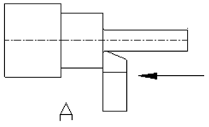 Figure A |
Figure B: depicts a standard turning tool with a lead angle. This angle enables for heavy roughing cuts. It also possible to turn the tool to create a semi-square shoulder. | 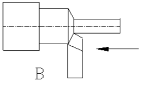 Figure B |
Figure C: nose has a very large radius, which helps with fine finishes on both light and heavy cuts. The tool can also be used to form a corner radius. | 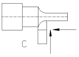 Figure C |
Figure D:depicts a rotated standard turning tool. Its nose leads the cutting edge to create light finishing cuts on the outside diameter and face of the shoulder. | 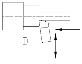 Figure D |
Figure E: depicts a form tool. Different forms can be ground into the tool, which will be reproduced onto the part. | 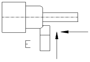 Figure E |
Figure F: depicts a facing tool. This cutter is used to face the end of a workpiece to provide for a smooth, flat finish. If the stock has a hole in the center, utilize a half-center to stabilize and support the workpiece. | 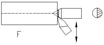 Figure F |
Figure G:depicts a grooving or under-cutting tool. As shown, it is used to cut grooves into the workpiece. When there are proper clearances, the tool can cut deeply, or cut to the left or right. | 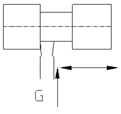 Figure G |
Figure H: depicts a parting tool. Parting tools cut off the stock at a certain length. This tool requires a preformed blade and holder. | 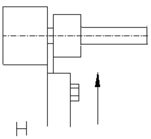 Figure H |
Figure I: depicts a 60° threading tool used to thread stock. | 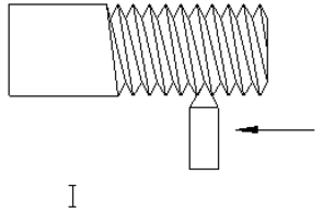 Figure I |
Question 4) How to setup a cutting tool for machining?
Answer 4) Cutting Tool setup for Machining
• Move the tool post to the left-hand side of the compound rest.
• Mount a tool holder in the tool post so that the set screw in the tool holder is about 1 inch beyond the tool post.
• Insert the proper cutting tool into the tool holder, having the tool extend .500 inch beyond the tool holder.
• Set the cutting tool point to center height. Check it with straight rule or tailstock.
• Tighten the tool post securely to prevent it from moving during a cut
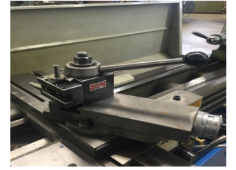
Figure : Tool post and Tool holder
To Mount Workpiece in Lathe
• Check that the line center is running true. If it is not running true, remove the center, clean all surfaces, and replace the center. Check again for trueness.
• Clean the lathe center points and the center holes in the workpiece.
• Adjust the tailstock spindle until it projects about 3 inch beyond tailstock.
• Loosen the tailstock clamp nut or lever.
• Place the end of the workpiece in the chuck and slide the tailstock up until it supports the other end of the workpiece.
• Tighten the tailstock clamp nut or level.
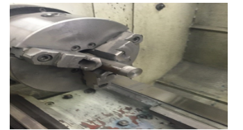
Figure : Workpiece in Lathe
Installing a Cutting Tool
• Tool holders are used to hold lathe cutting tools.
• To install, clean the holder and tighten the bolts.
• The lathe’s tool holder is attached to the tool post using a quick release lever.
• The tool post is attached to the machine with a T-bolt.

Figure : Installing a Cutting Tool
POSITIONING THE TOOL
To reposition the cutting tool, move the cross slide and lathe saddle by hand. Power feeds are also available. Exact procedures are dependent on the machine. The compound provides a third axis of motion, and its angle can be altered to cut tapers at any angle.
1. Loosen the bolts that keep the compound attached to the saddle.
2. Swivel the compound to the correct angle, using the dial indicator located at the compound’s base.
3. Tighten the bolts again.
4. The cutter can be hand fed along the chosen angle. The compound does not have a power feed.
5. If needed, use two hands for a smoother feed rate. This will make a fine finish.
6. Both the compound and cross slide have micrometer dials, but the saddle lacks one.
7. If more accuracy is needed when positioning the saddle, use a dial indicator that is attached to the saddle. Dial indicators press against stops.
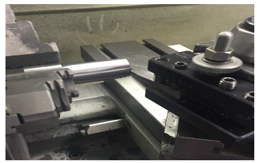
Figure: Positioning the Tool
Question 5) Explain the centering of workpiece?
Answer 5) CENTERING THE WORKPIECE
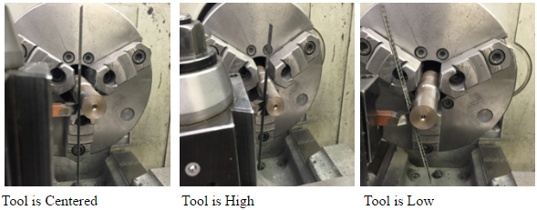
1. Place the steel rule between the stock and the tool.
2. The tool is centered when the rule is vertical.
3. The tool is high when the rule is lean forward.
4. The tool is low when the rule is lean backward.
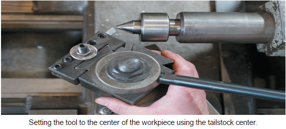
Tailstock Center
1. Reference the center of the tailstock when setting the tool.
2. Position the tip of the tool with the tailstock center.
Question 6) Explain the types of lathe machine?
Answer 6) Types of Lathe Machine
Lathe machine tool which is used for removing the excess material from the workpiece to give required shape and size to the workpiece.
Lathe machine has been categorized into the following types:
- Center or Engine Lathe
- Speed Lathe
- Capstan and Turret Lathe
- Tool Room Lathe
- Bench Lathe
- Automatic Lathe
- Special Purpose and
- CNC Lathe Machine
1) Speed Lathe:
Speed lathe is also called as Wood Lathe.
As the name indicates “Speed” the machine works with high speed. The headstock spindle is rotating at a very high speed. The parts having like headstock, tailstock, but it’s not having feed mechanism like center or engine lathe having. The feed we provide is manually operated.
The speed ranges of this machine operated between 1200 to 3600 RPM.
Speed lathe is used for spinning, centering, polishing and machining of wood.

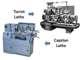
2) Capstan and Turret Lathe:
This is an advanced technology of the manufacturing industry.
The capstan and turret lathe machine used for Mass production (large Quantity) and it is a modified version of the engine lathe machine.
This machine is used where their sequence of operation is performed on the workpiece, there is no alternative operation performed on this machine.
These machines provided by hexagonal turret head instead of the tailstock in which multiple operations (Turning, facing, boring, reaming) performed in a sequence without changing its tool manually, after each operation the turret rotated.
It also consists of three tool post. It requires more floor space than other lathe machines.
Capstan and turret lathe is using for only large jobs.
The main advantage of using capstan and turret lathe is even less skilled operators can do a job.
3) Tool Room Lathe:
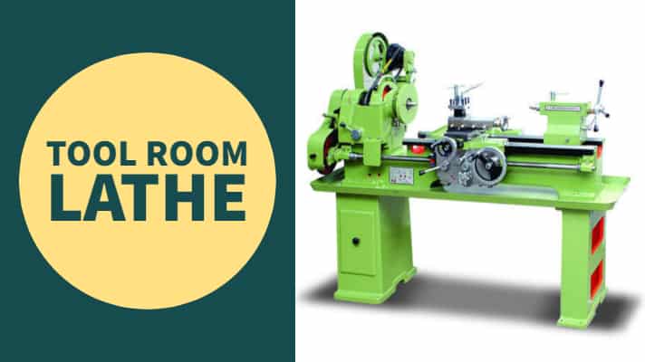
The tool room lathe machine operates to speed up to 2500 rpm.
The parts are almost the same similar to engine lathe machine but the parts are built very accurately and should be arranged in proper sequence because this lathe is used for highly precious work with very fewer tolerances.
It is mainly used in grindings, working on the tool, dies gauges and in machining work where accuracy is needed.
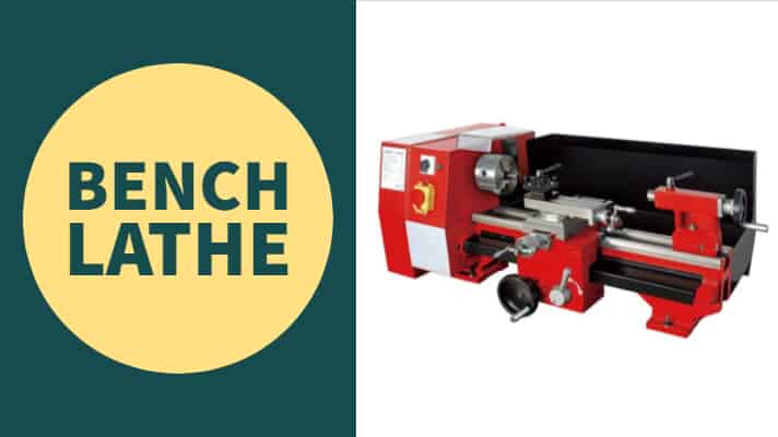
4) Bench Lathe:
Bench lathe machines are mounted on the bench.
This type of lathe machine is small in size and use for very small precision work. It has all the similar parts of engine lathe and speed lathe.
5) Automatic Lathe:
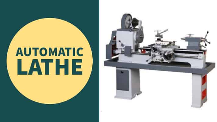
As the name indicates “Automatic lathe” performs work automatically.
Standard lathes have some drawbacks i.e. they are not used for mass production. But automatic lathes are used for mass production. Some mechanisms are responsible for the automation in it.
Here there is no need to change the tool manually because it changes automatically. Having this machine the main advantage is that a single operator can handle machines more than 4 to 5 machines at a time.
These types of lathes are high speed and heavy-duty.
6) Special Purpose Lathe:
As the name indicates “special purpose lathe” the machine performs the special types of operation which cannot be performed on standard and other machines. It is known for the heavy-duty production of identical parts. Some examples of special lathes include Vertical lathes, Wheel lathes, T-lathe, Multi Spindle lathes, Production lathes, Duplicate or tracer lathes, etc. Wheel lathe is used for machining of journals and rail rods. It is also used for turning the threads on locomotive wheels. The “T -lathe” is used for machining rotors for jet engines. The axis of the lathe bed is at right angles to the axis of the headstock spindle in the form of a T.
7) CNC Lathe Machine:
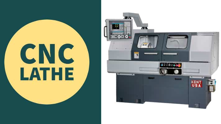
CNC stands for Computerized numerically controlled.
This is widely used as a lathe in the present time because of its fast and accurate working. It is one of the most advanced types. It uses computer programs to control the machine tool. Once the program is fed into the computer as per the program it starts operation with very high speed and accuracy.
Even do preplanned programmed machine is there in which once code is set for the various operations it can starts operation without changing code in the next time.
A semi-skilled worker can easily operate this after the initial setup is done.
These types of lathes are also used for mass production like capstan and turret but there is no programmed fed system. The components manufactured by these lathes are very accurate in dimensional tolerances.
Question 7) What are the precautions should be takes in drilling machine ?
Answer 7) Precautions which should be used in drilling Machine:
Safety is the most important factor that should be taken care of while using a drill machine to avoid any kind of harm to the operator. Improper use of the drill machine can cause serious injury to the operator.
The precautions which should be followed while using the drilling machine are as follows:
i) The machine tool should be strong enough to drill a hole in the work piece, otherwise, the parts may be deformed due to the cutting force generated. Drill feeding arrangement must be directionally stable.
Ii) To avoid any kind of error it must make sure that the Axis of the spindle, adapter, and tool must coincide.
Iii) Accurately ground drill should be used so that the uniform chips are produced by both cutting edges, otherwise, unbalanced forces may deflect the tool during machining
Iv) The workpiece must be held rigidly otherwise it can lead to Error in Shape Burrs. , error in hole location.
Question 8) writes the name of different types of drilling machine tools?
Answer 8) Drilling Machine tools
1. Drill
- A Drill is a fluted cutting tool used to originate or enlarge a hole in a strong material.
- It manufactures in a wide variety of types and sizes.
- The types of the drill commonly use :
i. Flat or Spade Drill
Ii. Straight Fluted Drill
Iii. Two Lip Twist Drill
Iv. Taper Shank Core Drill
v. Oil Tube Drill
Vi. Centre Drill
i. Flat or Spade Drill
- A flat drill is sometimes used when an equivalent sized twist drill is not available.
- It is usually made from a piece of round tool steel which is forge to shape and ground to size.
- The cutting edge differs from 90° – 120° and alleviation or leeway at the forefront is 3° – 8°.
Disadvantages
- This types of drill is that each time the drill is ground the diameter is reduced.
- It can’t be relief upon to drill a true straight hole, since the point of the drill has a tendency to run out of the centre.
- The chips don’t come out from the hole automatically, but tends to pack more or less tightly.
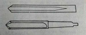
Ii. Straight Fluted Drill
- It has grooves or flutes running corresponding to the drill axis.
- This may be consider as a cutting tool having zero rake.
Straight Fluted Drill
- It’s inconvenient in standard practice as the chips don’t come out from the hole automatically.
- It’s mainly use in drilling Brass, Copper, or other softer materials.
Iii. Two Lip Twist Drill
- It was initially made by twisting a flat piece of tool steel longitudinally for several revolutions, then grinding the diameter and the point.
- The present day twist drills are made by machining two spiral flutes or grooves that run longwise around the body of the drill.
- Twist drill is end cutting tool.
- Different types of twist drills are:
a. Parallel Shank Jobbers Twist Drill
b. Parallel Shank Stub Series Twist Drill
c. Parallel Shank Long Series Twist Drill
d. Taper Shank Twist Drill
a. Parallel Shank Jobbers Twist Drill
- The Drill has two helical flutes with an equal shank of around a similar width as the cutting end.
- The diameter of the drill range from 0.2 – 16 mm increasing by 0.02 – 0.03 mm in lower arrangement to 0.25 mm in higher arrangement.
b. Parallel Shank Stub Series Twist Drill
- The drill is a shortened form of the equal shank twist drill, the shortening being on the flute length.
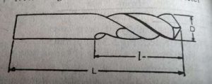
Image : Parallel Shank Stub
- The diameter of the drill ranges from 0.5 – 40 mm increasing by 0.3 mm in lower series to 0.25 – 0.5 mm in higher series.
c. Parallel Shank Long Series Twist Drill
- It has two helical flutes with a parallel shank of approximately the shank diameter as the cutting end.
- The overall length of this drill is the same as that of a taper shank twist drill of corresponding diameter.
- The diameter varies from 1.5 – 26 mm increasing by 0.3 mm in lower series to 0.25 mm in higher series.
d. Taper Shank Twist Drill
- It has two helical flutes with a taper shank for holding and driving the drill.
- The shank for these drills conforms to Morse tapers.
- The diameter ranges from 3 – 100 mm.
- The diameter increases by 0.3 mm in lowest series having Morse taper shank.
Iv. Taper Shank Core Drill
- These drills are planned for broadening cored, punched or penetrated gaps.
- These drills can’t originate a hole in solid material because the cutting edges don’t extend to the centre of the drill.
- The metal is remove by a chamfered edge at the end of each flute.
- The cutting action of a core drill is like to that of a rose reamer and it is regularly utilized as a roughing reamer.
v. Oil Tube Drill
- It used for drilling deep holes.
- This run lengthwise spirally through the body to carry oil directly to the cutting edges.
Vi. Centre Drill

Image : Center Drill
- These are straight shank, two fluted twist drills used when centre holes are drilled on the ends of a shaft.
- They are made in finer sizes.
Question 9) Explain the geometry of twist drill?
Answer 9) Geometry of a Twist Drill
- The following are the geometry of a twist drill are as follows :
1. Body
2. Flutes
3. Shank
4. Lips
5. Webs
6. Margin
7. Dead Centre
8. Lip relief angle
9. Point Angle
10. Helix Angle
11. Chisel Edge Angle
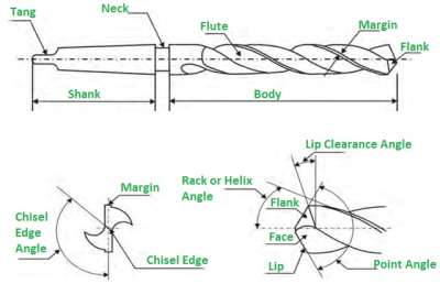
Image : Geometry of a Twist Drill
1. Body
- It is the piece of the drill that is fluted and eased.
2. Flutes
- It forms the cutting edges on the point.
- To allow the chips to escape.
- To cause the chips to curl.
- They permit the cutting fluid to reach the cutting edges.
3. Shank
- It is that part of the drill which fits to the holding device.
4. Lips
- It is the main cutting edges of the drill.
5. Webs
- It is the metal column in the drill to separate the flutes.
6. Margin
- It is the thin surface along the depression that decides the size of the drill and keeps the drill adjusted.
7. Dead Centre
- It is a sharp edge at the tip end of the drill.
8. Lip relief angle
- This is the axial relief angle at the outer corner of the lip.
9. Point Angle
- This is the angle includes between the cutting lips projected upon a plane parallel to the drill axis and parallel to the cutting lips.
10. Helix Angle
- It decides the rake edge of the front line of the drill.
11. Chisel Edge Angle
- It is the angle between the chisel edge and the cutting lip.
Question 10) write applications advantages and disadvantages of drilling machine ?
Answer 10)
Applications of Drilling Machine
- It use in the field of industries purpose like manufacturing, metalworking, etc.
- It use for producing holes like drilling, boring, etc.
- They also use in underground mining purpose.
- Use for the purpose of under cutting.
Advantages of Drilling Machine
- It requires less labour.
- It gives high precision and accuracy.
- No skill operators are required.
- It consumes less floor area.
Disadvantages of Drilling Machine
- It produces lots of torque at low speeds.
- It is not suitable for small production methods.
Question 11)write milling machine types?
Answer 11) Milling Machine Types
The types of milling machines are the following:
- Column and Knee Type Milling
- Vertical Milling
- Horizontal Milling
- Universal milling
- Fixed Bed Milling
- Simplex Milling
- Duplex Milling
- Triple Milling
- Planer Milling
- CNC Milling
- Tracer Milling