Unit 2
Optics, Fibre Optics And Laser
1Question:- In a Newton’s rings experiment the diameter of the 15th ring was found to be 0.59 cm and that of the 5th ring is 0.336 cm. If the radius of curvature of the lens is 100 cm, find the wave length of the light.
Solution:-
The given data are
Diameter of Newton’s 15th ring (D15) = 0.59 cm = 0.59×10⁻² m
Diameter of Newton’s 5th ring (D5) = 0.336 cm = 0.336 × 10⁻² m
Radius of curvature of lens (R) = 100 cm = 1 m
Wave length of light (λ) = ?
Here m is difference between rings = 15-5=10
λ = D2n+m - D2n / 4mR
λ = (0.59×10⁻² )2- (0.336 × 10⁻²)2 / 4 x 10 x 1
λ = 0.3481 x10⁻⁴ – 0.112896 x10⁻⁴ / 40
λ =0.00588 x 10⁻⁴ m
λ =5880 x 10-10 m
λ =5880Å
2 Question:- Discuss Newton’s Ring and also derive the formula for diameter of bright and dark fringes?
Solution:-
Newton’s Rings
Newton’s Rings are the circular interference pattern first discovered by physicist Sir Isaac Newton in 1704. It is cosists of concentric bright and dark rings with the point of contact of lens and the glass plate as centre,
The fringes obtained by interference of light waves by using the following arrangement
When a Plano convex lens with large radius of curvature is placed on a plane glass plate such that its curved surface faces the glass plate, a wedge air film (of gradually increasing thickness) is formed between the lens and the glass plate. The thickness of the air film is zero at the point of contact and gradually increases away from the point of contact.
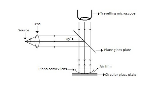
Figure Newton Ring Assembly
If monochromatic (means light with single wavelength) light is allowed to fall normally on the lens from a source 'S', then two reflected rays R1 (reflected from upper surface of the film) and R2 (reflected from lower surface of the air film) interfere to produce circular interference pattern. This interference pattern has concentric alternate bright and dark rings around the point of contact. This pattern is observed through traveling microscope.
Mathematical analysis of Newton’s Ring
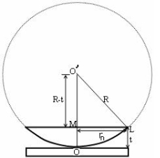
(OL)2 =(O’M)2-(ML)2 ……….(1)
R2=(R-t)2 +rn2
R2=R2 +t2-2Rt +rn2
Radius is large as compared to the thickness
So t2 is neglected as t2<< R2
R2=R2 +-2Rt +rn2
2Rt =rn2
Thickness of the film t =rn2 /2R ……….(2)
Theory of Fringes:
The effective path difference between the two reflected rays R1 and R2 for a wedge shaped film from equation
∆ = 2μtcos(r+θ) +λ/2 ……….(3)
If the light is incident normally on the lens,
r = 0 and near to point of contact θ is small;
Therefore near point of contact, (r+θ) approaches to 0 and cos(r+θ)=cos0=1
Therefore
∆ = 2μt+λ/2 ……….(4)
Also At point of contact t = 0 therefore the effective path difference ∆ = λ/2
Which is odd multiple of λ/2 Therefore the Central fringe is dark.
Bright Fringe : Condition of Maxima
For the condition of maxima the effective path difference
∆ = ±nλ
Using equation (4) ∆ = 2μt+λ/2 we have
2μt+λ/2= ±nλ
2μt = ± (2n-1)λ /2 ……….(5)
Diameter of Bright Rings
We know by equation (2) t =rn2 /2R substitute in equation (5) we have
2μ (rn2 /2R) = ± (2n-1)λ /2
rn2 = ± (2n-1)λR /2μ
We know diameter D=2r and for nth fringe Dn=2rn
So we have Dn2=± 2(2n-1)λR /μ
Dn=
The medium enclosed between the lens and glass plate is if air therefore,  =1. The diameter of nth order bright fringe will be
D= n=0,1,2,3,4……. ……….(6)
The diameter of bright ring is proportional to square root of odd natural numbers
Dark Fringe : Condition for Minima
For the condition of minima, The effective path difference
∆ =± (2n+1)λ /2
2μt+λ/2 =± (2n+1)λ /2
2μt= ±nλ ……….(7)
It is clear that for particular dark or bright fringe t should be constant.
Every fringe is the locus of points having equal thickness. Hence the fringes are circular in shape.
Diameter of Dark Rings
We know by equation (2) t =rn2 /2R substitute in equation (7) we have
2μ (rn2 /2R ) = nλ
rn2 = nλR/ μ
We know diameter D=2r and for nth fringe Dn=2rn
So we have Dn2= 4nλR/ μ
Dn= 
The medium enclosed between the lens and glass plate is if air therefore,  =1. The diameter of nth order bright fringe will be
Dn=  n=0,1,2,3,4……. ……….(8)
The diameter of dark ring is proportional to square root of natural numbers
3 Question:- Newton’s rings are observed in the reflected light of wave length 5900 Å. The diameter of 10th dark ring is 0.5 cm. Find the radius of curvature of the lens used.
Solution:- The given data are
Wave length of light (λ) = 5900 Å= 5900 × 10–10 m
Diameter of 10th Newton’s dark ring (D10) = 0.5 cm = 0.5 × 10⁻² m
Radius of curvature of lens (R) = ?
Formula is D2n = 4nλR
R= D2n /4nλ
R= (0.5 × 10⁻²)2 /4x 10 x 5900 × 10–10
R= 0.25 x10⁻⁴ /236x10-7
R=1.059m
4 Question:- Show that the fringe width of newton’s rings reduces with increase in n.
Or
Show that the spacing of newton’s rings gets closer with increase in n.
Solution:- Spacing between Fringes
The Newton’s rings are not equally spaced because the diameter of ring does not increase in the same proportion as the order of ring and rings get closer and closer as ‘n’ increases.
For example the diameter of dark ring is given by Dn=  where n=0,1,2,3,4…….
D3 - D2 = -
-  = (
= ( -
- )
) = 0.635
D7 – D6 = -
-  = (
= ( -
- )
) = 0.392
D10– D9 = -
-  = (
= ( -
- )
) = 0.324
From above result we conclude that the fringe width reduces with increase in n.
5 Question:- What happens when we use white light in newton’s rings method instead of monochromatic light?
Solution:- Newton’s Ring with White Light
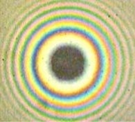
If the monochromatic source is replaced by the white light, dark and bright fringes are not produced. Because the diameter of the rings depends upon wavelength and it is proportional to the square root of wavelength.
If If the monochromatic source is replaced by the white light superposition of rings take place due to different wavelength. Few coloured rings are seen around dark centre later illumination is seen in the field of view. As shown in below figure.
6 Question :- The velocity of light in water is 2.2 X 10⁸ m/s. What is the polarizing angle of incidence?
Solution:-
Refractive index of water = Speed of light in space/Speed of light in water
= 3 x10⁸/2.2 x108
= 1.3636
Using Brewster’s Law, Angle of incidence = tan-1μ
= tan-1(1.3636)
= 53.74.
7 Question :- Explain Production of Polarized Light by Reflection?
Solution:-
The Brewster’s law can be used to polarise the light by reflection. When unpolarised light is incident on the boundary between two transparent media, the reflected light is polarised with its electric vector perpendicular to the plane of incidence when the refracted and reflected rays make a right angle with each other.
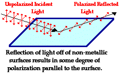
Thus we have seen that when reflected wave is perpendicular to the refracted wave, the reflected wave is a totally polarised wave. The electric field vectors of all unpolarized light may be resolved into two components as follows;
- Tangential component- in the plane of incidence.
- Normal components – in the plane perpendicular to plane of incidence.
The angle of incidence in this case is called Brewster’s angle


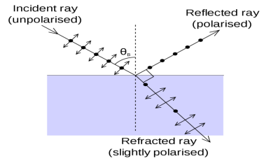

If the angle of incidence θi is varied, the reflected coefficient ‘r’ for the em waves corresponding to the tangential component will vary as shown in figure. As θi increases r will decrease.
At θi = Brewster angle (about 57° for glass) r will be zero and no reflection of the tangential component will take place.
The reflected beam will contain light waves having only the normal component for the electric field as shown in figure that is the reflected light will be plane polorized with the oscillations of electric field vector normal to the plane of incidence.
Cause of Polrizaton by Reflection
The em waves are generated because of the oscillation of electric charge. The electric field vectors of the transmitted ray act on the electrons in the dielectric.
Since the intensity of em wave emitted by the oscillating charge is maximum in a direction normal to the plane of oscillation, and zero along the line of oscillations for the plane polarized light having electric field vector in the plane of incidence, there will be no emition of em waves in a direction normal to the reflected ray. In figre the direction along which no emission should accur is called as zero intensity line. Let the angle between the reflected ray and the zero intensity line be 𝛿 the angle between the reflected and tranmitted ray is π/2 + 𝛿 suppose we arrange the angle of incidence such that
n=sinθi / sinθr
n=sinθi / sin(π/2 – θi)
n=sinθi / cosθi
n=tan θi
That is possible when
θi + θr = π/2 according to Brewster’s law
From figure
θi + θr+ π/2 + = π
As θi + θr = π/2
So π/2+ π/2 + = π
= 0
The line of zero intensity and the refected ray will coincide. Thuse there will be no reflection of light when the angle of incidence is equal to Brewster’s angle.
Thus the unpolarized light can be polarized by reflection as the reflected beam will contain light waves having electric field vector oscilating along normal to the plane of the incidence only.
8 Question :- Discuss Laurent’s half shade Polarimeter also give mathematical formula to find specific rotation?
Solution:-
Polarimeter – it is an optical instrument used to measure the angle of rotation of plane polarized light when it is passed through an optically active substance.
By measuring the angle, the specific rotation of an optically active substance can be determined.
Two types of polarimeters are generally used in the laboratory now a days Laurent’s Half Shade Polarimeter and Biquartz Polarimeter. We will discuss Laurent’s Half Shade Polarimeter.
Construction
- S is source of monochromatic light placed at the focus of convex
- Just after the convex lens there is a Nicol Prism P is placed. This prism acts as a polariser.
- H is a half shade device which divides the field of polarised light emerging out of the Nicol P into two halves generally of unequal brightness.
- T is a glass tube in which optically active solution is filled.
- The light after passing through T is allowed to fall on the analyzing Nicol A which can be rotated about the axis of the tube. (Don’t get confuse here, we already discussed in previous section that Nicol prism acts as a polariser as well as analyser).
- The rotation of analyser can be measured with the help of a scale.

Laurent’s half shade polarimeter is shown in Figure
Working
To understand the working of this device we have to know the need of a Laurent half shade device. For this we assume that half shade device is not present.
In this basic setup (without the half-shade A) you are looking for the maximum and minimum brightness, which then tells you that the analyzer A is precisely aligned with the output rotation.
When tube is empty placed the analyzer in such a position that the view of field is completely dark. Note the position of the analyzer with the help of circular scale.
Now filled the tube with optically active solution and it is set in its proper position. The optically active solution rotates the plane of polarization of the light emerging out of the polariser P by some angle. So the light is transmitted by analyzer A and the field of view of telescope becomes bright.
Now the analyzer is rotated by a finite angle so that the field of view of telescope again become dark. This will happen only when the analyzer is rotated by the same angle by which plane of polarization of light is rotated by optically active solution.
The position of analyzer is again noted. The difference of the two readings will give you angle of rotation of plane of polarization.
But here the difficulty associated with this procedure that when analyzer is rotated for the total darkness, then it is attained gradually and hence it is difficult to find the exact position correctly for which complete darkness is obtained.
To overcome above difficulty half shade device is introduced between polariser P and glass tube T.
Half Shade Device
- It consist of two semi-circular plates ACB and ADC.
- One half ACB is made of glass while other half is made of quartz.
- Both the halves are joined together.
- The quartz is cut parallel to the optic axis.
- Thickness of the quartz is selected in such a way that it introduces a path difference of ‘A/2 between ordinary and extraordinary ray.
- The thickness of the glass is selected in such a way that it absorbs the same amount of light as is absorbed by quartz half.
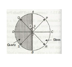
- Let us consider that the vibration of polarisation is along OP. On passing through the glass half the vibrations remain along OP. But on passing through quartz half these vibrations will split into o and e-components.
- The e-components are parallel to the optic axis while o-component is perpendicular to optic axis.
- The o-component travels faster in quartz and hence an emergence 0-component will be along OD instead of along OC.
- Thus components OA and OD will combine to form a resultant vibration along OQ which makes same angle with optic axis as OP.
Now if the Principal plane of the analysing Nicol is parallel to OP then the light will pass through glass half passable. Hence glass half will be brighter than quartz half or we can say that glass half will be bright and the quartz half will be dark. Similarly if principal plane of analysing. Nicol is parallel to OQ then quartz half will be bright and glass half will be dark.
When the principal plane of analyzer is along AOB then both halves will be equally bright. On the other hand if the principal plane of analyzer is along DOC. Then both the halves will be equally dark.
Thus it is clear that if the analysing Nicol is slightly disturbed from DOC then one half becomes brighter than the other. Hence by using half shade device, one can measure angle of rotation more accurately.
Mathematically
The specific rotation is given by S=θ/lC where l is length of tube and C is concentration.
9 Question :-A tube of length 20cm containing a 10% sugar solution rotates the plane of polarization by 13.2°. What is the specific rotation of sugar solution?
Solution:-
The specific rotation is given by S = 10θ/lC
given θ = 13.2°
C = 0.1 g/cc
l = 20 cm
Therefore,
S = 10 X 13.2/20 X 0.1
S= 66°
10 Question:- Discuss principle, construction and working of Optical Fibre?
Solution:-
A cable which is used to transmit the data through fibres (threads) or plastic (glass) is known as optical fibre cable. This cable includes a pack of glass threads which transmits modulated messages over light waves.
Principle: Optical Fibre works on the principle of Total Internal Reflection.
Total internal reflection:-
When the light ray travels from denser medium to rarer medium the refracted ray bends away from the normal. When the angle of incidence is greater than the critical angle, the refracted ray again reflects into the same medium. This phenomenon is called total internal reflection. The refracted ray bends towards the normal as the ray travels from rarer medium to denser medium. The refracted ray bends away from the normal as it travels from denser medium to rarer medium.
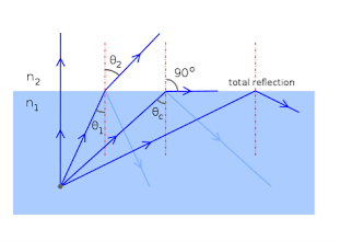
Figure – Total Internal Reflection
Characteristics of Optical Fibre
- It has a large bandwidth.
- The optical frequency of 2 x 10¹⁴ Hz can be used and hence the system has higher bandwidth.
- Thus optical fibres have greater information-carrying capacity due to greater bandwidth.
- In optical fibre system transmission losses are as low as 0.1 db/km.
- Optical fibre are of small size and light weight as compared to electrical fibre.
- Optical fibre communication is free from electromagnetic interference.
- Optical fibre do not carry high voltage and current hence they are safer than electrical cable.
- Optical Fibre are flexible and have high tensile strength. Thus can be bent or twisted easily.
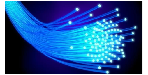
Figure: Optical Fibre
Construction of Optical Fibre:
It consists of a very thin fibre of silica or glass or plastic of a high refractive index called the core. The core has a diameter of 10 um to 100 um. The core is enclosed by a cover of glass or plastic called cladding. The refractive index of the cladding is less than that of the core (which is a must condition for the working of the optical fibre). The difference between the two indicates is very small of order 10-3. The core and the cladding are enclosed in an outer protective jacket made of plastic to provide strength to the optical fibre. The refractive index can change from core to cladding abruptly (as in step-index fibre) or gradually (as in graded-index fibre).

Figure Representation of Optical Fibre
Working of Optical Fibre
When a ray of light is incident on the core of the optical fibre at a small angle, it suffers refraction and strikes the core-cladding interface, As the diameter of the fibre is very small hence the angle of incidence is greater than the critical angle. Therefore, the ray suffers total internal reflection at the core-cladding interface and strikes the opposite interface. At this interface also, the angle of incidence is greater than the critical angle, so it again suffers total internal reflection. Thus, the ray of light reaches the other end of the fibre after suffering repeated total internal reflections along the length of the fibre. At the other end, the ray suffers refraction and emerges out the optical fibre.
We can see that the light travels in the core in a guided manner. Hence the communication through the optical fibre is sometimes referred as an optical waveguide.
11 Question:- Explain the terms acceptance angle, numerical aperture and acceptance cone.
Or
Derive expressions for the numerical aperture and fraction change in refractive index change of an optical fibre.
Solution:-
Acceptance angle
Definition:- Acceptance angle is defined as the maximum angle of incidence at the interface of air medium and core medium for which the light ray enters into the core and travels along the interface of core and cladding.
Let n0 be the refractive indices of air
n1 be the refractive indices of core
n2 be the refractive indices of cladding
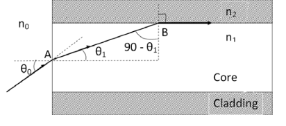
Let a light ray OA is incident on the interface of air medium and core medium with an angle of incidence θ0
The light ray refracts into the core medium with an angle of refraction θ1 and the refracted ray AB is again incidenting on the interface of core and cladding with an angle of incident (90- θ1)
If (90- θ1) is equal to the critical angle of core and cladding media then the ray travels along the interface of core and cladding along the path BC. If the angle of incident at the interface of air and core θ1< θ0 then (90- θ1) will be greater than the critical angle. Therefore,
The total internal reflection takes place.
According to Snell’s law at point A
n0 Sin θ0 = n1 Sin θ1
Sin θ0= (n1 / n0) Sin θ1 ………(1)
According to Snell’s law at point B
n1 Sin(90- θ1) = n2 Sin90 ………(2)
n1 Cosθ1 = n2 as (Sin90=1)
Cosθ1 = n2 /n1
Sinθ1 = (1-Cos2 θ1)1/2
Sinθ1= (1- (n2 /n1)2)1/2
Sinθ1= ( n12- n22 )1/2/ n1 ………(3)
We know Sin θ0= (n1 / n0) Sin θ1 from equation (1)
Substitute the value of Sinθ1 from equation (3)
Sinθ0= (n1 / n0) *( n12- n22 )1/2/ n1
On simplification
Sinθ0= ( n12- n22 )1/2/ n0
θ0=Sin-1 ( n12- n22 )1/2/ n0
Acceptance Angle is θ0=Sin-1 ( n12- n22 )1/2/ n0 ………(4)
Numerical aperture
Definition: -Numerical aperture is defined as the light gathering capacity of an optical fibre and it is directly proportional to the acceptance angle. Numerically it is equal to the sin of the acceptance angle.
NA = Sin(acceptance angle)
NA = Sin {Sin-1 (( n12- n22 )1/2/ n0)} from equation (4)
NA = (( n12- n22 )1/2/ n0) ………(5)
If the refractive index of the air medium is unity i.e. n0=1 put in (5)
NA = ( n12- n22 )1/2 ………(6)
Fractional change in refractive index
∆= (n1- n2)/ n1
n1∆ = (n1- n2) ………(7)
From equation (6), we have
NA = {( n1- n2 )( n1+n2 )}1/2
NA = { n1∆ (n1+n2 )}1/2 as n1∆ = (n1- n2) by Eq(7)
NA = { n1∆ 2n1}1/2 n1 ≈ n2, so n1+n2 =2n1
NA = n1{2∆}1/2
This gives the relation between Numerical aperture and Fractional change in refractive index.
Acceptance Cone
If all possible directions of acceptance angle are considered at the same time. We get a cone corresponding to surface known as Acceptance Cone
This is the maximum angle, represented in three-dimensional view as a cone, at which an optical fibre will accept incident light. Within that cone, as defined by those angles, a light source can inject an optical signal into the fibre core and the signal will remain in the core, reflecting off of the interface between the core and cladding.

12 Question:- What are the advantages and disadvantages of an optical fibre?
Solution:-
Advantages of fibre optic communication
The optical fibre communication has more advantages than convectional communication.
1. Enormous Bandwidth
2. Low Transmission Loss
3. Electric Isolation
4. Signal Security
5. Small Size and Less Weight
6. Immunity Cross Talk
1. Enormous bandwidth:- The information carrying capacity of a transmission system is directly proportional to the frequency of the transmitted signals. In the coaxial cable transmission the bandwidth range is up to around 500MHz only. Where as in optical fibre communication, the bandwidth range is large as 105 GHZ.
2. Low transmission loss:- The transmission loss is very low in optical fibres (i.e.KmdB/2.0) than compare with the conventional communication system. Hence for long distance communication fibres are preferred.
3. Electric isolation:- Since fibre optic materials are insulators, they do not exhibit earth and interface problems. Hence communicate through fibre even in electrically danger environment.
4. Signal security:- The transmitted signal through the fibre does not radiate, unlike the copper cables, a transmitted signal cannot be drawn from fibre without tampering it. Thus the optical fibre communication provides 100% signal security.
5. Small size and less weight:- The size of the fibre ranges from 10μm to 50μm, which is very small. The space occupied by the fibre cable is negligibly small compared to conventional electrical cables. Optical fibres are light in weight.
6. Immunity cross talk:- Since the optical fibres are dielectric wave guides, they are free from any electromagnetic interference and radio frequency interference. Since optical interference among different fibres is not possible, cross talk is negligible even many fibres are cabled together.
Disadvantages of Optical Fibre
The disadvantages of optical fibre include the following
- The main disadvantages of these cables are installation is expensive and difficult to fix together.
- The optical fibre cables are very difficult to merge & there will be a loss of the beam within the cable while scattering.
- Fibre optic cables are compact and highly vulnerable while fitting
- These cables are more delicate than copper wires.
- Special devices are needed to check the transmission of fibre cable.
13 Question:- Write a note on the applications of an optical fiber?
Solution:-
Application of optical fibre
- Optical fibres are extensively used in communication system.
- Optical fibres are in exchange of information between different computers
- Optical fibres are used for exchange of information in cable televisions, space vehicles, submarines etc.
- Optical fibres are used in industry in security alarm systems, process control and industrial auto machine.
- Optical fibres are used in pressure sensors in biomedical and engine control.
- Optical fibres are used in medicine, in the fabrication in endoscopy for the visualization of internal parts of the human body.
- Sensing applications of optical fibres are Displacement sensor, Fluid level detector, Liquid level sensor, Temperature/pressure sensor and Chemical sensors
- Medical applications of optical fibres are Gastroscopy, Orthoscopic, Couldoscope, Peritonescope and Fibrescope.
14 Question:- Explain how the optical fibres are classified?
Solution:-
Types of Optical Fibres
The types of optical fibres depend on the refractive index, materials used, and mode of propagation of light.
The classification based on the refractive index is as follows:
- Step Index Fibres: It consists of a core surrounded by the cladding, which has a single uniform index of refraction.
- Graded Index Fibres: The refractive index of the optical fibre decreases as the radial distance from the fibre axis increases.
The classification based on the materials used is as follows:
- Plastic Optical Fibres: The polymethylmethacrylate is used as a core material for the transmission of the light.
- Glass Fibres: It consists of extremely fine glass fibres.
The classification based on the mode of propagation of light is as follows:
- Single-Mode Fibres: These fibres are used for long-distance transmission of signals.
- Multimode Fibres: These fibres are used for short-distance transmission of signals.
The mode of propagation and refractive index of the core is used to form four combination types of optic fibres as follows:
- Step index-single mode fibres
- Graded index-Single mode fibres
- Step index-Multimode fibres
- Graded index-Multimode fibres