Unit 2
- Explain the representation of sinusoidal waveform?
Sinusoidal Waveform Construction
Coil Angle ( θ ) | 0 | 45 | 90 | 135 | 180 | 225 | 270 | 315 | 360 |
e = Vmax.sinθ | 0 | 70.71 | 100 | 70.71 | 0 | -70.71 | -100 | -70.71 | -0 |
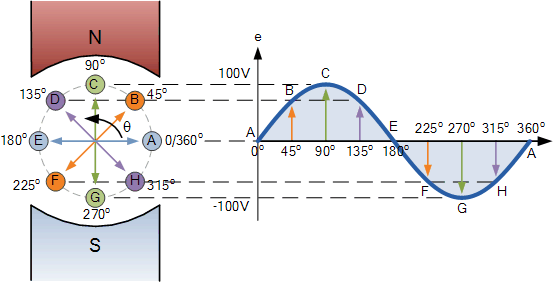
The points on the sinusoidal waveform are obtained by projecting across from the various positions of rotation between 0o and 360o to the ordinate of the waveform that corresponds to the angle, θ and when the wire loop or coil rotates one complete revolution, or 360o, one full waveform is produced.
From the plot of the sinusoidal waveform we can see that when θ is equal to 0o, 180o or 360o, the generated EMF is zero as the coil cuts the minimum amount of lines of flux. But when θ is equal to 90o and 270o the generated EMF is at its maximum value as the maximum amount of flux is cut.
Therefore a sinusoidal waveform has a positive peak at 90o and a negative peak at 270o. Positions B, D, F and H generate a value of EMF corresponding to the formula: e = Vmax.sinθ.
Then the waveform shape produced by our simple single loop generator is commonly referred to as a Sine Wave as it is said to be sinusoidal in its shape. This type of waveform is called a sine wave because it is based on the trigonometric sine function used in mathematics, ( x(t) = Amax.sinθ ).
2. Explain peak and RMS value ?
Average Value:
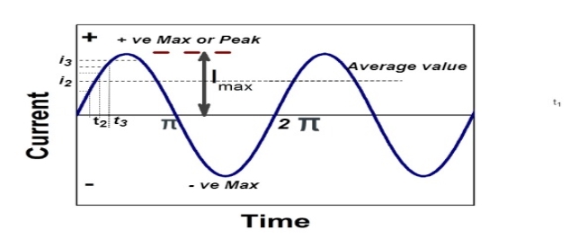
The arithmetic mean of all the value over complete one cycle is called as average value

 =
= 
For the derivation we are considering only hall cycle.
Thus  varies from 0 to ᴫ
i = Im Sin


Solving
We get


Similarly, Vavg=
The average value of sinusoid ally varying alternating current is 0.636 times maximum value of alternating current.
RMS value: Root mean square value
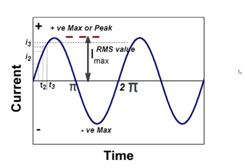
The RMS value of AC current is equal to the steady state DC current that required to produce the same amount of heat produced by ac current provided that resistance and time for which these currents flows are identical.

I rms = 
Direction for RMS value:
Instantaneous current equation is given by
i = Im Sin 
But 
I rms = 
= 
=
=
Solving
=
=
Similar we can derive
V rms=  or 0.707 Vm
 the RMS value of sinusoidally alternating current is 0.707 times the maximum value of alternating current.
3. Explain the phasor representation of AC quantities?
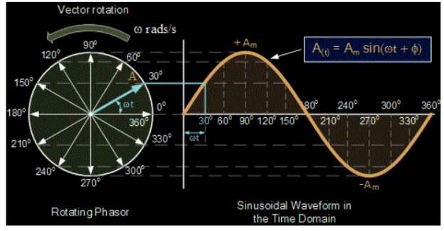
A phasor is a vector that is used to represent a sinusoidal function. It rotates about the origin with an angular speed ω.
The vertical component of phasors represents the quantities that are sinusoidally varying for a given equation, such as v and i. Here, the magnitude of the phasors represents the peak value of the voltage and the current.
From the figure shown above, we can see the relation between a phasor and the sinusoidal representation of the function with respect to time. The projection of the phasor on the vertical axis represents the value of the quantity.
For example, in the case of a current or a vector phasor, the projection of the phasor on the vertical axis, given by vmsinωt and imsinωt respectively, gives the value of the current or the voltage at that instant.
From the phasor diagram, it is easy to detect that one of two quantities are in the same phase. For example, if for a given circuit, the phasors for the voltage and the current are in the same direction for all instances, the phase angle between the voltage and the current is zero.
4. Define real power , apparent power and reactive power?
- Apparent power (S) : it is defined as product of rms value of voltage (V) and current (I) or it is the total power / max power
S = V 
 Unit - volt – Ampere (VA)
In kilo – K. V. A.
2. Real power / true power / active power / useful power : [P] it is defined as the product of rms value active component or it is the average power or actual power consumed by the resistive part (R) in the given combinational circuit
It is measured in watts
P = VI Cos Ø watts /km where Ø is the power factor angle
3. Reactive power / Imaginary / useless power [Q]
It is defined as the product of voltage current and sine of angle between V and


Volt Amp Relative
 Unit – V A R

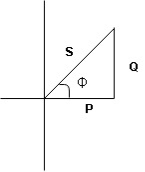
 Power triangle
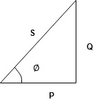
- As we know power factor is cosine of angle between voltage and current
i e P.F. = Cos 
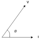
In other words also we can derive it from impedance triangle
Now consider Impedance triangle in R – L- ckt.
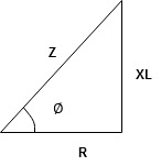
From  now Cos
  = power factor =
 power factor = Cos
  or
or 
5.Explain the analysis of single phase R-L-C circuit?
R-L-C series circuit
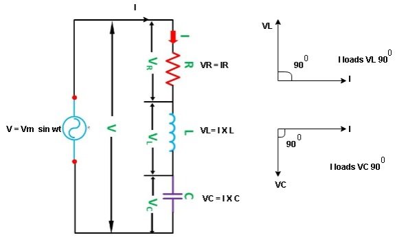
Consider ac voltage source V = Vm sin wt connected across combination of R L and C. When I flowing in the circuit voltage drops across each component as shown below.
VR = IR, VL = I  L, VC = I
  C
C
- According to the values of Inductive and Capacitive Reactance I e XL and XC decides the behaviour of R-L-C series circuit according to following conditions
① XL> XC, ② XC> XL, ③ XL = XC
① XL > XC: Since we have assumed XL> XC
 Voltage drop across XL> than XC
 VL> VC A
- Voltage triangle considering condition A

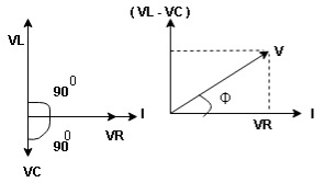
VL and VC are 180 0 out of phase .
Therefore cancel out each other
 Resultant voltage triangle
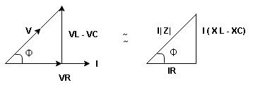
Now V = VR + VL + VC c phasor sum and VL and VC are directly in phase opposition and VL
 VC
VC their resultant is (VL - VC).
From voltage triangle
V = 
 V =
V = 
 V = I
V = I 

Impendence  : divide voltage
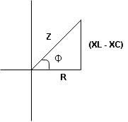
Rectangular form Z = R + j (XL – XC)
Polor form Z =  l + Ø B
Where  =
= 
And Ø = tan-1 
- Voltage equation : V = Vm Sin wt
- Current equation
i =  from B
i =  L-Ø C
L-Ø C
As VL VC the circuit is mostly inductive and
  I lags behind V by angle Ø
 Since i =
  L-Ø
L-Ø
 i = Im Sin (wt – Ø) from c
- XC
 XL :Since we have assured XC
  XL
XL
 the voltage drops across XC
  than XL
 XC
XC  XL (A)
 voltage triangle considering condition (A)
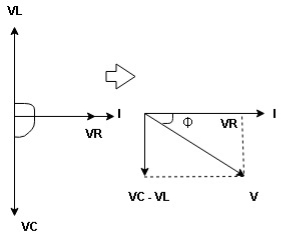
 Resultant Voltage
Now V = VR + VL + VC  phases sum and VL and VC are directly in phase opposition and VC
 VL
VL  their resultant is (VC – VL)
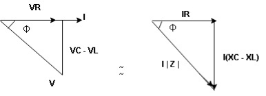
From voltage 
V = 
V = 
 V =
V = 
 V =
V = 

 Impedance
  : Divide voltage
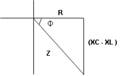
- Rectangular form : Z + R – j (XC – XL) – 4th qurd
Polar form : Z =  L -
L -
Where 
And Ø = tan-1 – 
- Voltage equation : V = Vm Sin wt
- Current equation : i =
 from B
 - i =
 L+Ø C
L+Ø C
As VC  the circuit is mostly capacitive and
  leads voltage by angle Ø
Since i =  L + Ø
L + Ø
 Sin (wt – Ø) from C
- Power
 :
:
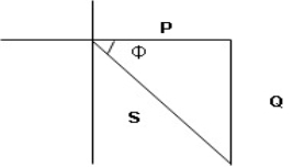
- XL= XC (resonance condition):
ɡȴ XL= XC then VL= VC and they are 1800 out of phase with each other  they will cancel out each other and their resultant will have zero value.
Hence resultant V = VR and it will be in phase with I as shown in below phasor diagram.
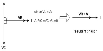
From above resultant phasor diagram
V =VR + IR
Or V = I  lZl
lZl
Because lZl + R
Thus Impedance Z is purely resistive for XL = XC and circuit current will be in phase with source voltage.

 Since VR=V Øis zero when XL = XC
  power is unity
Ie pang = Vrms I rms cos Ø = 1 cos o = 1
Maximum power will be transferred by condition. XL = XC
6.Explain series and parallel resonance?
Resonance in series RLC circuits
Definition: it is defined as the phenomenon which takes place in the series or parallel R-L-C circuit which leads to unity power factor
Voltage and current in R – L - C ckt. Are in phase with each other
Resonance is used in many communicate circuit such as radio receiver.
Resonance in series RLC series resonance in parallel RLC anti resonance / parallel resonance.
- Condition for resonance XL = XC
- Resonant frequency (Fr) : for given values of R-L-C the inductive reactance XL become exactly aqual to the capacitive reactance Xc only at one particular frequency. This frequency is called as resonant frequency and denoted by (fr)
- Expression for resonant frequency(fr) : we know thet XL = 2ƛ FL - Inductive reactance
Xc =  - capacitive reactance
At a particular frequency ȴ = fr, the Inductive and capacitive reactance are exactly equal
 XL = XC ……at ȴ = fr
Ie  L =
L = 
 fr2 =
fr2 = 
 fr =
fr =  H2
H2
And  = wr =
  rad/sec
7. Explain three phase balanced circuits?
Three phase circuit is the polyphase system where three phases are send together from generator to the load. Each phase are having a phase difference of 1200 , i.e 1200 angle electrically. So from the total of 3600 , three phase are equally divided into 1200 each. The power in three phase system is continuous as all the three phases are involved in generating the total power. The sinusoidal waves for 3 phase system is shown below
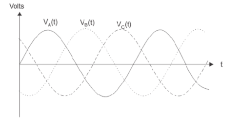
The three- phase can be used as single phase each. So, if the load is single phase, then one phase can be taken from the three- phase circuit and the neutral can be used as ground to complete the circuit.
A set of three impedances interconnected in the form of a star or delta form a 3-phase star or delta connected load. If the three impedances are identical and equal then it is a balanced 3-phase load, otherwise it is an unbalanced 3-phase load.
8. Explain voltage and current in star-delta relations?
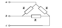
Let us consider a balanced 3-phase delta connected load
Determination of phase voltages:
VAB = V∠0 0 , VBC = V∠-1200 , VCA = V∠ − 240 0 = V∠120 0
Determination of phase currents:
Phase current = Phase voltage/ Load impedance
IAB = VAB/ Z ; IBC = VBC/Z ; ICA = VCA/Z
Determination of line currents:
Line currents are calculated by applying KCL at nodes A,B,C
IA = IAB – ICA ; IB = IBC - IAB ; IC = ICA - IBC
Balanced star connected load:
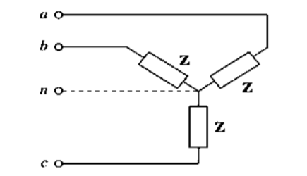
Let us consider a balanced 3-phase star connected load.
For star connection, phase voltage= Line voltage/(√3)
For ABC sequence, the phase voltage is polar form are taken as
VAN = Vph <-90 ; VCN = Vph<150 ; VBN = Vph <30
For star connection line currents and phase currents are equal
IA = VAN / Z ; IB = VBN/Z ; IC = VCN/Z
To determine the current in the neutral wire apply KVL at star point
IN + IA + IB + IC =0
IN = -(IA + IB + IC) since they are balanced.
In a balanced system the neutral current is zero. Hence if the load is balanced, the current and voltage will be same whether neutral wire is connected or not. Hence for a balanced 3-phase star connected load, whether the supply is 3- phase 3 wire or 3-phase 4 wire, it is immaterial. In case of unbalanced load, there will be neutral current.
9. Explain power measurement in three phase AC circuits?
Power measurement in an AC circuit is measured with the help of a Wattmeter. A wattmeter is an instrument which consists of two coils called Current coil and Potential coil.
For measuring the power in a 3 phase or Poly Phase system, more than one wattmeter is required, or more than one readings are made by one wattmeter. If more than one wattmeter is connected for the measurement, the process becomes convenient and easy to work with instead of taking various readings with one wattmeter.
The number of wattmeters required to measure power in a given polyphase system is determined by Blondel’s Theorem.
According to Blondel’s theorem – When power is supplied by the K wire AC system, the number of wattmeters required to measure power is one less than the number of wire i.e. (K-I), regardless the load is balanced or unbalanced.
Hence, three wattmeters are required to measure power in three-phase, four-wire system, whereas, only two wattmeters are required to measure the power in 3 phase, 3 wire system.
Three Wattmeter method is employed to measure power in a 3 phase, 4 wire system. However, this method can also be employed in a 3 phase, 3 wire delta connected load, where power consumed by each load is required to be determined separately.
The connections for star connected loads for measuring power by three wattmeter method is shown below:
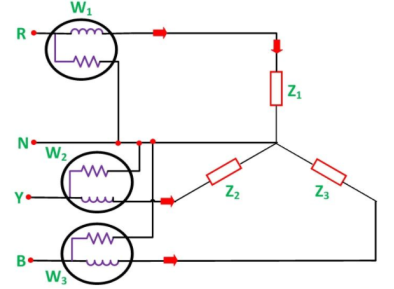
The total power in a three -wattmeter method of power measurement is given by the algebraic sum of the readings of three wattmeters. i.e.
Total power P = W1 + W2 + W3
Where
W1 = V1 I1
W2 = V2 I2
W3 = V3 I3
10. Mention the advantages of three phase power measurement?
Three-phase supplies have properties that make them very desirable in electric power distribution systems:
- The phase currents tend to cancel out one another, summing to zero in the case of a linear balanced load. This makes it possible to reduce the size of the neutral conductor because it carries little or no current. With a balanced load, all the phase conductors carry the same current and so can be the same size.
- Power transfer into a linear balanced load is constant, which helps to reduce generator and motor vibrations.
- Three-phase systems can produce a rotating magnetic field with a specified direction and constant magnitude, which simplifies the design of electric motors, as no starting circuit is required.