Unit 8
Question Bank
Question 1) Difference between Pump and Compressor?
Answer 1) Difference between pump and compressor:
S. No. | Pump | Compressor |
1. | It is used to move the fluid from one place to another at | It is used to increase pressure or potential energy of |
2. | It increase pressure of fluid by move it at higher height. | It increases pressure of fluid by compressing it. |
3. | There is no change volume from inlet to outlet of pump. | There is change in volume from inlet to outlet from the |
4. | It is used to transport liquid like water, oil etc. | It is used to transport gases. |
5. | The may or may not change in pressure of fluid. | There must be change in pressure of fluid. |
6. | It is mostly used to increase energy of incompressible | It is mostly used to increase energy of compressible fluid. |
7. | It does not have storage. It only sucks the fluid from one | It has storage capacity. It can store gases and deliver it |
Question 2) What are Difference between Turbine and Pump
Answer 2) Difference between Turbine and Pump
1. In terms of flow of energy: In turbine, input is of hydraulic energy (water under pressure) and output is of mechanical energy (torque of the shaft). In pump, input is of mechanical energy (torque of the shaft) and output is of hydraulic energy (water under pressure).
2. Hydraulic pressure head: Available turbine head decreases with increasing flow (friction losses). Total dynamic head to be generated by pump increases with increasing flow.
3. Direction of rotation: Turbine runner rotates in the opposite direction of a pump impeller.
4. Direction of Torque: In both, in the turbine and in the pump direction of torques is in the same direction.
Question 3) Difference between Impulse and Reaction Turbine
Answer 3) the main difference between Impulse and Reaction Turbine
S.no | Impulse Turbine | Reaction Turbine |
1. | In an impulse turbine, the steam flows through the nozzle and strike on the moving blades. | In the reaction turbine, first, the steam flows through the guide mechanism and then flows through the moving blades. |
2. | Steam strikes on the buckets with kinetic energy. | The steam glides over the moving blades with both pressure and kinetic energy. |
3. | During the flow of steam through moving blades, its pressure remains constant. | During the flow of steam through moving blades its pressure reduces. |
4. | The steam may or may not be admitted to the whole circumference. | The steam must be admitted over the whole circumference. |
5. | The blades of impulse turbine are symmetrical. | The blades of reaction turbine are not symmetrical. |
6. | While gliding over the blades the relative velocity of steam remains constant. | In reaction turbine, while gliding over the blades the relative velocity of steam increases. |
7. | For the same power developed, the number of stages required is less. | For the same power developed, the number of stages required is more. |
8. | The direction of steam flow is radial to the direction of turbine wheel. | The direction of steam flow is radial and axial to the turbine wheel. |
9. | It requires less maintenance work. | It requires more maintenance work. |
10. | It is suitable for low discharge. | It is suitable for medium and high discharge. |
11. | Pelton Wheel is the example of impulse turbine. | Francis turbine, Kaplan turbine etc. are the examples of reaction |
Question 4) What is draft tube explains the types?
Answer 4) Draft Tube:
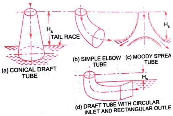
The pressure at the exit of the runner of a reaction turbine is generally less than atmospheric pressure. The water at the exit cannot be directly discharged to the tailrace. A tube or pipe of the gradually increasing area is used for discharging water from the exit of the turbine to the tailrace. This tube of increasing area is called the draft tube
The water after doing work on the runner passes on to the tall race through a tube called a draft tube. It is made of riveted steel plate or pipe or a concrete tunnel. The cross-section of the tube increases gradually towards the outlet. The draft tube connects the runner exit to the tailrace. This tube should be drowned approximately 1 meter below the tailrace water level.
Function of draft tube –
I) To decrease the pressure at the runner, exit to a value less than atmospheric pressure and thereby increase the effective working head.
ii) To recover a part of electric energy into pressure head at the exit of the draft tube. This enables easy discharge to the atmosphere.
Types of draft tube:
I. Conical draft tube
ii Simple elbow draft tube
iii. Moody spreading draft tube
iv. Elbow draft tube with circular cross-section at inlet and rectangular at outlet
(1) Conical Draft Tubes—
This is known as a tapered draft tube and used in all reaction turbines where conditions permit. It is preferred for low specific speed and Francis turbine. The maximum cone angle is 8° (a = 40°). The hydraulic efficiency is 90%.
(2) Simple Elbow Tubes-
The elbow type draft tube is often preferred in most of the power plants. If the tube is large in diameter; ‘it may be necessary to make the horizontal portion of some other section. A common form of section used is over or rectangular. It has low efficiency of around 60%.
(3) Moody Spreading Tubes-
This tube is used to reduce the whirling action of discharge water when the turbine runs at high speed under low head conditions. The draft tube has an efficiency of around 85%.
(4) Elbow with circular inlet and rectangular outlet—
This tube has circular cross-section at the inlet and rectangular section at the outlet. The change from the circular section to the rectangular section takes place in the bend from the vertical leg to the horizontal leg. The efficiency is about 85%.

Question 5) Explain Parts of Reciprocating Pump:
Answer 5) The Parts of Reciprocating Pump are as follows.
- Water Sump
- Strainer
- Suction Pipe
- Suction Valve
- Cylinder
- Piston and Piston rod
- Crank and Connecting rod
- Delivery valve
- Delivery pipe
The explanation for the parts of Reciprocating pump are as follows.
- Water Sump:
It is the source of water. From the sump, water is to be transported to the delivery pipes by the usage of the piston.
II. Strainer:
It acts as a mesh that can screen all the dirt, dust particles, etc. from the sump. If there is no strainer, then the dirt or dust also enters into the cylinder which can jam the region and affects the working of the pump.
III. Suction Pipe:
The main function of the suction pipe is to collect the water from the sump and send it to the cylinder via a suction valve. The suction pipe connects the water sump and the cylinder.
IV. Suction Valve:
It is a non-return valve which means it can take the fluid from the suction pipe and send it to the cylinder but cannot reverse the water back to it. In the sense, the flow is unidirectional.
This valve opens only during the suction of fluid and closes when there is a discharge of fluid to outside.
V. Cylinder:
It is a hollow cylinder made of cast iron or steel alloy and it consists of the arrangement of piston and piston rod.
VI. Piston and Piston rod:
For suction, the piston moves back inside the cylinder and for discharging of fluid, the piston moves in the forward direction.
The Piston rod helps the piston to move in a linear direction i.e. either the forward or the backward directions.
VII. Crank and Connecting rod:
For rotation, the crank is connected to the power source like engine, motor, etc. whereas the connecting rod acts as an intermediate between the crank and piston for the conversion of rotary motion into linear motion.
VIII. Delivery Pipe:
The function of the delivery pipe is to deliver the water to the desired location from the cylinder.
IX. Delivery valve:
Similar to the suction valve, a delivery valve is also a Non-return valve. During suction, the delivery valve closes because the suction valve is in opening condition and during Discharge, the suction valve is closed and the delivery valve Is opened to transfer the fluid.
Question 6) Explain Reciprocating Pump Advantages:
1) This pump is self-priming – Not require filling the cylinders by starting.
2) This pump can work in wide pressure range.
3) Priming is not necessary in pump.
4) Provide elevated suction lift.
5) They are used for air also.
6) No priming is needed in the Reciprocating pump compared to the Centrifugal pump.
7) It can deliver liquid at high pressure from the sump to the desired height.
8) It exhibits a continuous rate of discharge.
9) It can work due to the linear movement of piston whereas the centrifugal pump works on the rotary velocity of the impeller.
Question 7) Explain Reciprocating Pump Disadvantages:
1. Flow is not consistent, so we have to fit a bottle at equally ends.
2. Flow is extremely less and cannot use for high flow process.
3. High wear and tear, so need lot maintenance.
4. Early price is much more in this pump.
5. Additional heavy and large in shape.
6. Low discharging capacity
7. The maintenance cost is very high due to the presence of a large number of parts.
8. The initial cost of this pump is high.
9. Viscous fluids are difficult to pump.
Question 8) Explain Centrifugal pump:
Answer 8)
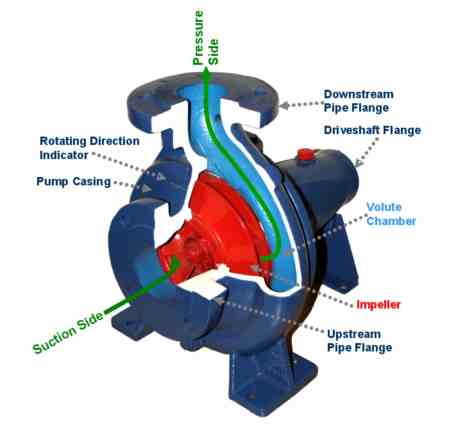
Centrifugal pump is a hydraulic machine which converts mechanical energy into hydraulic energy by the use of centrifugal force acting on the fluid. These are the most popular and commonly used type of pumps for the transfer of fluids from low level to high level. It is used in places like agriculture, municipal (water and wastewater plants), industrial, power generation plants, petroleum, mining, chemical, pharmaceutical and many others.
Pumps are the mechanical devices that convert mechanical energy into hydraulic energy. They are generally used to raise the water or other fluids from lower elevation to higher elevation. So, pumps are generally classified into centrifugal pump and positive displacement pump. Centrifugal pumps are non- positive displacement pumps. They work on the principle of centrifugal action.
Question 9) Explain Casing?
Answer 9)
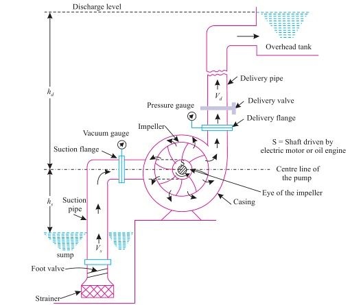
It is a pipe which is connected at the upper end to the inlet of the pump to the centre of impeller which is commonly known as eye. The double end reaction pump consists of two suction pipe connected to the eye from both sides. The lower end dips into liquid in to lift. The lower end is fitted in to foot valve and strainer.

Fig 3: Main Components of Centrifugal Pump.
Commonly three types of casing are used in centrifugal pump are –
1) Volute casing: – It is spiral type of casing in which area of flow increase gradually. The increase in area of flow decreases the velocity of flow and increases the pressure of water.
2) Vortex casing: – if a circular chamber is introduced between casing and the impeller, the casing is known as vortex casing.
3) Casing with guide blades: – the impeller is surrounded by a series of guide blades mounted on a ring know as diffuser.
Question 10) Explain Working of Centrifugal Pump?
Answer 10)
Water is drawn into the pump from the source of supply through a short length of pipe (suction pipe). Impeller rotates; it spins the liquid sitting in the cavities between the vanes outwards and provides centrifugal acceleration with the kinetic energy.
This kinetic energy of a liquid coming out an impeller is harnessed by creating a resistance to flow. The first resistance is created by the pump volute (casing) that catches the liquid and shows it down.
In the discharge nozzle, the liquid further decelerates and its velocity is converted to pressure according to BERNOULLI’S PRINCIPAL.

Let us understand in detail, how a Centrifugal pump works. Centrifugal pumps are used to induce flow or raise a liquid from a low level to a high level. These pumps work on a very simple mechanism. A centrifugal pump converts rotational energy, often from a motor, to energy in a moving fluid.
The two main parts that are responsible for the conversion of energy are the impeller and the casing. The impeller is the rotating part of the pump and the casing is the airtight passage which surrounds the impeller. In a centrifugal pump, fluid enters into the casing, falls on the impeller blades at the eye of the impeller, and is whirled tangentially and radially outward until it leaves the impeller into the diffuser part of the casing. While passing through the impeller, the fluid is gaining both velocity and pressure