Unit 4
- Explain the generation of rotating magnetic field?
Consider a stator of an electric motor where three-phase winding is physically distributed in the stator core in such a manner that winding of each phase is separated from other by 120o in space.
Although the vector sum of three currents in a balanced three-phase system is zero at any instant, but the resultant of the magnetic fields produced by the currents is not zero rather it will have a constant non-zero value rotating in space in respect to time.
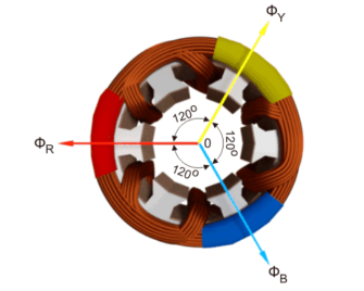
The magnetic flux produced by the current in each phase can be represented by the equations given below. This is a similar representation of current is a three-phase system as the flux is cophasial with the current.
ɸ R = ɸ m sin(wt)
ɸ Y = ɸ m sin(wt -120 0 )
ɸ B = ɸm sin(wt – 240 0 )
Where, φR, φY and φB are the instantaneous flux of corresponding Red, Yellow and Blue phase winding, φm amplitude of the flux wave. The flux wave in the space can be represented as shown below.

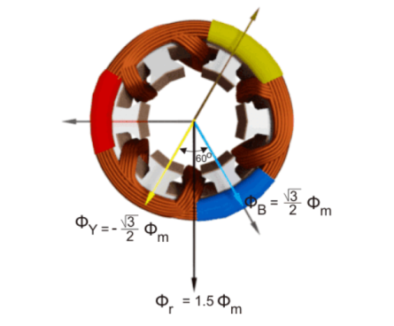
First consider the point 0.
ɸ R = ɸ m sin(0) = 0
The value of
ɸ Y = ɸ m sin(0 – 120 0) = ɸ m sin(-1200) = -  ɸ m
ɸ m
The value of φB is
ɸ B = ɸm sin(0 – 240 0 )= ɸm sin (-240 0 ) =  ɸ m
ɸ m
The resultant of these fluxes at that instant (φr) is 1.5φm which is shown in the figure below.
From the graphical representation of flux waves, consider the point 1, where ωt = π / 6 or 30o.
ɸ R = ɸ m sin(30) = ½ ɸ m
The value of
ɸ Y = ɸ m sin(30 – 120 0) = ɸ m sin (-90) = -ɸm.
The value
ɸ B = ɸm sin(30 – 240 0 ) = ɸ m sin (-210) = ½ ɸ m
The resultant of these fluxes at that instant (φr) is 1.5φm which is shown in the figure below. Here it is clear the resultant flux vector is rotated 30o further clockwise without changing its value.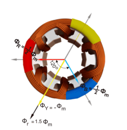
Now, on the graphical representation of flux waves, we will consider the point 2, where ωt = π / 3 or 60o.
ɸ R = ɸ m sin(60) =  ɸ m
ɸ m
The value of
ɸ Y = ɸ m sin(60 – 120 0) = ɸ m sin (-60) = -  ɸm.
ɸm.
The value of
ɸ B = ɸ m sin(60 – 240 0) = ɸ m sin (-180) = 0
The resultant of these fluxes at that instant (φr) is 1.5φm which is shown in the figure below. It shows that the resultant flux vector is rotated 30° further clockwise without changing its value.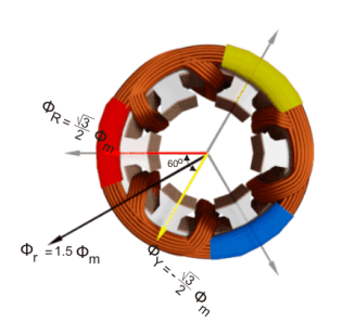
Now, consider the point 3, where ωt = π / 2 or 90o.
ɸ R = ɸ m sin(90) = ɸ m
The value of
ɸ Y = ɸ m sin(90 – 120 0) = ɸ m sin (-30) = -  ɸm.
ɸm.
The value of
ɸ B = ɸ m sin(90 – 240 0) = ɸ m sin (-150) = -1/2 ɸ m.
The resultant of these fluxes at that instant (φr) is 1.5φm which is shown in the figure below. The resultant flux vector is rotated 30o further clockwise without changing its value.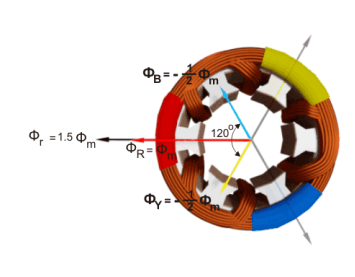
In this way we can prove that the due to balanced supply applied to the three phase stator winding a rotating or revolving magnetic fields is established in the space.
2. Explain the operation of three phase induction motor?
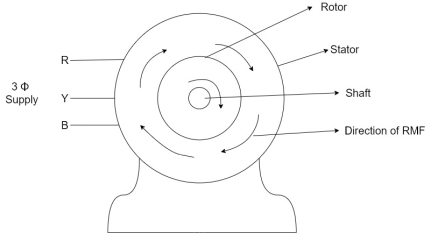
- When the 3Ф A.C supply is connected across the stator of induction motor, the current starts flowing through the stator wdg. i.ethe stator condition.
- Due to this current of flux (Ф) is established in the stator wdg. This flux (Ф) is alternating (changing) in nature. Thus this flux links with the rotor also, and a a Rotating Magnetic Field(RMF) is produced.
- This flux (Ф) induces emf in the rotor also. The RMF is produced in the air gap between stator and rotor.
The rotor is rotating part which is till stationary, show the rotating magnetic field is cut by stationary rotor and an EMF is induced in the rotor winding. According to faraday's law of EMI the rotor EMF gives the rise to rotor current which opposes the main cause producing it according Lenz's law.
3.Explain single phase induction motor?
A Single-Phase Induction Motor consists of a single phase winding which is mounted on the stator of the motor and a cage winding placed on the rotor. A pulsating magnetic field is produced, when the stator winding of the single-phase induction motor shown below is energized by a single phase supply.

The word Pulsating means that the field builds up in one direction falls to zero and then builds up in the opposite direction. Under these conditions, the rotor of an induction motor does not rotate. Hence, a single-phase induction motor is not self-starting. It requires some special starting means.
If the 1 phase stator winding is excited and the rotor of the motor is rotated by an auxiliary means and the starting device is then removed, the motor continues to rotate in the direction in which it is started.
The performance of the single-phase induction motor is analysed by the two theories. One is known as the Double Revolving Field Theory, and the other is Cross Field Theory. Both the theories are similar and explain the reason to produce torque when the rotor is rotating.
4. Explain separately excited DC motor?
Separately excited dc motor has field coils similar to that of shunt wound dc motor. The name suggests the construction of this type of motor. Usually, in other DC motors, the field coil and the armature coil both are energized from a single source. The field of them does not need any separate excitation. But, in separately excited DC motor, separate supply Provided for excitation of both field coil and armature coil. Figure below shows the separately excited dc motor.
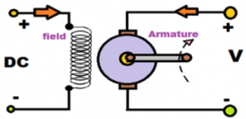
Here, the field coil is energized from a separate DC voltage source and the armature coil is also energized from another source. Armature voltage source may be variable but, independent constant DC voltage is used for energizing the field coil. So, those coils are electrically isolated from each other, and this connection is the specialty of this type of DC motor
In a separately excited motor, armature and field windings are excited form two different dc supply voltages. In this motor,
• Armature current Ia = Line current = IL = I
• Back emf developed , Eb = V – I Ra
where V is the supply voltage and Ra is the armature resistance.
• Power drawn from main supply , P = VI
• Mechanical power developed ,
Pm = Power input to armature – power loss in armature
5. Explain the characteristics of DC motor?
Operating characteristics of Separately excited dc motor
Both in shunt wound dc motor and separately excited dc motor field is supplied from constant voltage so that the field current is constant. Therefore these two motors have similar speed -armature current and torque – armature current characteristics. In this type of motor flux is assumed to be constant.
• Speed – armature current (N – Ia) characteristics: We know that speed of dc motor is proportional to back emf / flux i.e Eb / φ . When load is increased back emf Eb and φ flux decrease due to armature resistance drop and armature reaction respectively .However back emf decreases more than φ so that the speed of the motor slightly decreases with load.
• Torque – armature current ( τ – Ia) characteristics : Here torque is proportional to the flux and armature current . Neglecting armature reaction, flux φ is constant and torque is proportional to the armature current Ia . τ – Ia characteristics is a straight lien passing through the origin. From the curve we can see that huge current is needed to start heavy loads. So this type of motor do not starts on heavy loads.
Speed control of separately excited DC motor
Speed of this type of dc shunt motor is controlled by the following methods:
I. Field control methods: Weakening of field causes increase in speed of the motor while strengthening the field causes decreases the speed. Speed adjustment of this type of motor is achieved from the following methods:
II. Field rheostat control: – Here a variable resistance is connected in series with the field coil. Thus the speed is controlled by means of flux variation.
Reluctance control involving variation of reluctance of magnetic circuit of motor.
Field voltage control by varying the voltage at field circuit while keeping armature terminal voltage constant.
III. Armature control methods: Speed adjustment of separately excited DC motor by armature control may be obtained by any one of the following methods :
i. Armature resistance control: – Here, the speed is controlled by varying the source voltage to armature. Generally, a variable resistance is provided with the armature to vary the armature resistance.
ii. Armature terminal voltage control involving variation of variation of voltage in armature circuit.
6. Explain synchronous generator ?
The synchronous generator or alternator is an electrical machine that converts the mechanical power from a prime mover into an AC electrical power at a particular voltage and frequency.
The synchronous motor always runs at a constant speed called synchronous speed.
It works on the principle of Faraday laws of electromagnetic induction. The electromagnetic induction states that electromotive force induced in the armature coil if it is rotating in the uniform magnetic field.
The EMF will also be generated if the field rotates and the conductor becomes stationary. Thus, the relative motion between the conductor and the field induces the EMF in the conductor. The wave shape of the induces voltage always a sinusoidal curve.
Construction of Synchronous Generator
The rotor and stator are the rotating and the stationary part of the synchronous generator. They are the power generating components of the synchronous generator.
The rotor has the field pole, and the stator consists the armature conductor. The relative motion between the rotor and the stator induces the voltage between the conductor.

7. Explain the applications of synchronous generator?
- The three-phase synchronous generators have many advantages in generation, transmission and distribution.
- The large synchronous generators use in the nuclear, thermal and hydropower system for generating the voltages.
- The synchronous generator with 100MVA power rating uses in the generating station. The 500MVA power rating transformer use in the super thermal power stations.
- The synchronous generators are the primary source of the electrical power. For the heavy power generation, the stator of the synchronous generator design for voltage ratings between 6.6 kV to 33 kV.
8.Mentions the applications of DC motor?
Separately excited dc motors have industrial applications. They are often used as actuators. This type of motors is used in trains and for automatic traction purposes.
9.Mention the applications of induction motor?
- Used for the loads which require a gradual buildup of torque.
- Used for the loads that require speed control.
- The wound rotor induction motors are used in conveyors, cranes, pumps, elevators and compressors.
10. A 220 V shunt motor has armature and field resistances of 0.2 Ω and 220 Ω respectively. The motor is driving load torque, TL ∝ n 2 and running at 1000 rpm drawing 10 A current from the supply. Calculate the new speed and armature current if an external armature resistance of value 5 Ω is inserted in the armature circuit. Neglect armature reaction and saturation.
Solution :
The field current and armature currents corresponding to the initial operating point are
If 1 = 1A and Ia1 = 9A
Now torque and back emf equations are
Te1 = Kt x 1 x 9 = TL1
Eb1 = Kg x 1 x1000= V – Ia Ra = 220 – 9 x 0.2 = 218.2 V
Let the new steady state armature current be Ia2 and the new speed be n2. In this new condition the torque and the back emf equations are
Te2 = kt x1xIa2 =TL2
Eb2 = kg x 1xn2 = V -Ia2(ra + ext)= 220 -Ia2 x 5.2 = 218.2V
Taking the ratios of te2 and te1 we get
Te2/Te1 = TL2/TL1 = kt x 1xIa2/ktx1x9
N2 2 / 10002 = Ia 2/9
Ia2 /9 = n2 2 /10002
Or n2/1000 = [Ia2] ½ /3
Taking ratios Eb2 and Eb1 we get
Kg x 1 x n2 / kg x 1 x 1000 = 220- Ia2 x 5.2/218.2
= n2/1000 = 220-Ia2x5.2/218.2
 /3 = 220- Ia2 x5,2/218.2
0.005Ia2 -1.43 Ia2 + 9.15 =0
Solving we get Ia2 = 7A
=  x 1000 rpm = n2 = 881. 9 rpm.