Unit 3
- What are magnetic materials?
The response of a material when subjected to an external magnetic field is the root of magnetism. The spinning electrons in the material behave like tiny magnets. These tiny magnets are aligned in the direction of applied magnetic field and thereby the material is magnetized.
An applied magnetic field H incites a response from a 2 material called magnetic induction B. The relationship between B and H can be defined by
B = μo H + μo I ------------------------(1)
Where I is the magnetic moment per unit volume. μo is a constant called the permeability of free space. So, the ratio of I to H is called the susceptibility and is indicative of the ease with which a material can be magnetized by an applied magnetic field .
 ----------------------------------------(2)
Equation(2) is called the suspectability.
2. Explain BH characteristics?
The response of a material when subjected to an external magnetic field is the root of magnetism. The spinning electrons in the material behave like tiny magnets. These tiny magnets are aligned in the direction of applied magnetic field and thereby the material is magnetized.
An applied magnetic field H incites a response from a 2 material called magnetic induction B. The relationship between B and H can be defined by
B = μo H + μo I ------------------------(1)
Where I is the magnetic moment per unit volume. μo is a constant called the permeability of free space. So, the ratio of I to H is called the susceptibility and is indicative of the ease with which a material can be magnetized by an applied magnetic field .
 ----------------------------------------(2)
Equation(2) is called the suspectability.
3. Explain single phase transformer?
A single-phase transformer is a type of power transformer that utilizes single-phase alternating current, meaning the transformer relies on a voltage cycle that operates in a unified time phase. They are often used to step-down long distance and localized transmission currents into power levels more suitable for residential and light-commercial applications. The ratio of primary (input) windings to secondary (output) windings determines the change in current. Single-phase transformers with a 1:1 ratio can be used to isolate circuits. Single-phase transformers abide by Ohm's law, and outside of minor inherent loss due to heat, do not create or remove power.
Single-phase transformers are more popular than three-phase transformers in non-urban areas, as the cost of a three-phase distribution network is much higher, and the overall electrical demand is lower. The highest voltage available in a single-phase network is regulated by utility infrastructure and industrial regulations. A single-phase transformer is frequently used for power distribution and voltage reduction for residential and commercial applications. When used with appliances, the lower voltage output is often rectified into DC current before powering appliances, such as a computer.
4. Explain three phase transformer?
A three-phase transformer is made of three sets of primary and secondary windings, each set wound around one leg of an iron core assembly. Essentially it looks like three single-phase transformers sharing a joined core as in Figure below.

Three phase transformer core has three sets of windings.
Those sets of primary and secondary windings will be connected in either Δ or Y configurations to form a complete unit. The various combinations of ways that these windings can be connected together.
5. Explain ideal and practical transformer?
The B-H curve of transformer core is never linear rather it becomes flat as the value of magnetizing current increases.
This means, transformer exciting current will not be in phase with the core flux. In fact, exciting current leads the core flux by some angle “α”. This angle is known as Hysteretic Angle.
This angle is dependent on the hysteresis loop of the core material.
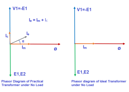
In an ideal transformer, magnetization curve is assumed to be linear. This means, magnetizing current and core flux are in phase.
In practical/real transformer, the exciting current (current in primary winding under no load condition) drawn from the source is composed of magnetizing current (Im) and core loss component (Ic). This is because, core loss is supplied by the primary source only. However, in an Ideal Transformer, as there is no core loss, the exciting current is equal to magnetizing current.
6. Explain auto transformer?
An auto Transformer is a special types of transformer such that a part of the winding is common to both primary as well as secondary
It has only One winding wended on a laminated magnetic core
With the help of auto Transformer the voltage can be stepped up and stepped down at any desired value
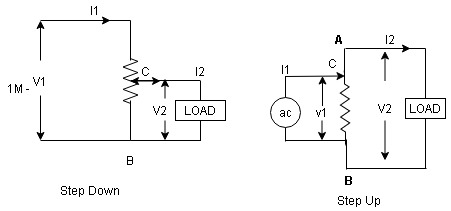
Fig A shows auto T/F as step down T/F variable terminal B C is connected to load and it acts as secondary wdg.
The position of point C is called as topping point can be selected as per requirement
Fig. B show auto T/F as step up T/F variable terminal B C is connected to supply side ie ac side and it acts as secondary winding
The operating principle of auto Transformer is same as that of 2 winding Transformer
7. Explain its advantages and its disadvantages?
Advantages
- Weight of copper required in an auto Transformer is always loss than that of the conventional 2 winding Transformer and hence it is chaper
- Com[act in size and loss costly.
- Losses taking place in Transformer is reduced hence efficiency is higher than conventional Transformer.
- Due to reduced resistance, voltage, regulation is better than conventional T/F.
Disadvantage :
As low voltage and high voltage sides are not separate then there is always risk of electric shocks when use for high vtg. Applications
Applications
- Starting squirrel cage induction motor and synchronous motor.
- Auto transformer as dimmer stat
- Used as vari ac to vary a. c Voltage
8. Explain the difference between shell type and core transformer?
- It consist of magnetic frame with 1. 3 Limbs
2 limbs
2. single magnetic circuit 2. Double magnetic ckt.
3. Winding encircles the core 3. Core encircles the winding
4. One window 4. Two window
5. Cylindrical type winding is used5. Sandwich type is used
6. Easy to repair 6. Not easy repair
7. Preferred for Low voltage application 7. Preferred for high voltage application
8. Provides better cooling since winding8. Does not provide effective cooling as
Are uniformly distributed on 2 limbs the winding are surrounding core.
9. Explain mutual induction?
A major application of transformer is to increase voltage before transmitting electrical energy over a long distance through conductors and to again reduce voltage at place where it is to be used.
Symbol
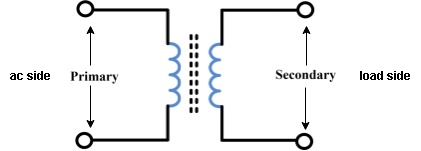
- Primary winding : (ac supply side) For MCQs
The winding which is connected to supply is called primary side
2. Secondary winding : (load side) for MCQs
The winding which is connected to load is called as secondary winding
When 2 coil are inductively coupled and if current in one coil is changed uniformly then an emf get induced in another coil”
- When alternating voltage V1 is applied to primary winding am alternating current I1 flows in it producing alternating flux in the core.
- As per Faradays Law of Electromagnetic Induction 1 an emf E1 is induced in the primary winding E = N1

- The emf induced in the primary winding is nearly equal and opposite to applied voltage V1
- Assuming leakage flux to be negligible almost whole flux produced in primary winding links with secondary winding thence emf induced in the secondary winding E2 = N2

10. Explain the construction and working of transformer?
- There a 2 types of winding
- Concentric or cylindrical
- Sandwiched type
- Cylindrical
L.V. = low voltage H.V. = high voltage are mounted on same limb to minimum leakage .
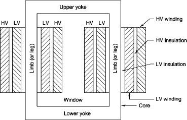
L.V. Winding placed inside and H.V. Winding placed outside with (proper insulation between the winding as it is easy to insulated L.V. Winding) than H.V. Winding.
2. Sandwiched
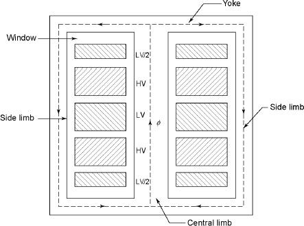
The H.V. And L.V. Winding are divided into no. Of small coils and there small windings are interleaved.
(the top and bottom winding are L.V. Coils because they are close to core)
- Transformer tank : wholes assembly of winding and core placed inside the Transformer tank (sheet metal tank) which is filled with Transformer oil or insulating oil which acts as an (insulator or coolant ) MCQ
- Transformer oil : (The function of oil is to remove efficiently the heat generated in core and in winding)
- Moisture should not be allowed which creeps the insulation which achieved by closed Transformer tank.
(To increase cooling surface are tubes or fins are provided)
- Conservator tank : above tank T/F tank there is one small tank in which same empty space is always provided above the oil level. (this space is required for oil to expand or contract due to temperature change) MCQ
However during contraction outside air can have moisture which will deteriorate the insulating properly of oil.
- Breather : the air goes in or out through the breather (To reduce the moisture content of their air . Same drying agents such as (silica gel or) calcium chloride) is used in the breather (The dust particles present in air are also removed by breather)
- Buccholz Relay : (for incipient (slowly increasing) faults
There is pipe connecting rain tank and conservator. On the pipe a protective device called Buccholz Relay is mounted.
When the Transformer is about to be faulty and draw range current the oil becomes very hot and decompose.
During this process different types of gases are liberated.(The Bucchoz Relay get operated by these gases) and gives an alarm to the operator. ɡȴ the fault continues to persist then there lay will trip off main circuit breaker to protect the Transformer.
- Explosion Vent :
An explosion Vent or relief value is the bent up pipe filled on the main tank.
(The explosion vent consist of aluminium of oil ) when the T/F becomes faulty the cooling oil get decomposed and various types of gases are liberated
(ɡȴ the gas pressure exodus certain level then the aluminium of oil (diagram) in explosion vent will burst) to release pressure. The will save main tank from getting damaged