Question Bank
Unit-4
Q1) A 1200V 50Hz delta connected IM has a star connected slip ring rotor with phase transformation ratio of 3.6. The rotor resistance and standstill leakage reactance are 0.012 and 0.25 ohm per phase. Find the rotor current with slip ring shorted. The power factor at start with slip ring shorted.
Sol: In this case the primary phase voltage is same as line voltage.
The rotor phase standstill voltage = 1200 x [1/3.6] = 333.3V
a) Rotor impedance/phase =  = 0.2503Ω
b) Rotor phase current at start = 333.3/0.2503=1331.8A
Power Factor = 0.012/0.2503=0.048 lagging
Q2) A rotor of 6-pole 50Hz IM is rotated by some means at 1000 rpm. Find i) Rotor voltage. Ii) rotor frequency iii) rotor slip.
Sol: N=1000rpm
F=50Hz
The synchronous speed Ns=120f/P=120x50/6=1000rpm
i) Rotor voltage Er=sE
S=Ns-N/Ns x100 = {[1000-1000]/1000} x 100 = 0
Since, s=0 Er=0
Ii) Rotor Frequency fr=sfs
Since, s=0
fr=0
Iii) Rotor slip s=0
Q3) A star connected rotor of an IM has a standstill impedance of 0.2+j3 ohm per phase and the rheostat impedance per phase of 6+j2 ohm. The motor has induced emf of 80V. Find the rotor current at standstill with the rheostat in the circuit.
Sol: For standstill condition
Voltage/Rotor phase= 80/ = 46.2V
Starter impedance/phase = 6.2+j5=7.96
Rotor current/phase= 46.2/7.96=5.8
p.f= cos 38.88=0.778
Q4) A 3-phase 50Hz 6-pole IM has full load slip of 2%. The rotor resistance and standstill rotor reactance per phase is 0.002 and 0.048 ohm. Find the ratio of maximum full load torque and the speed at which the maximum torque occurs.
Sol: Ns=120f/P=120 x 50/6=1000rpm
Slip at max.torque ( smT) = rotor resistance/standstill rotor reactance=0.002/0.048=0.042
Now the speed becomes = (1-0.042) x 1000=958rpm

 = 15.5 x 10⁻³
Q5) A 6-pole 50 Hz 3-phase IM develops a maximum torque of 158.7 N-m at 1335 rpm. The resistance of the star connected rotor is 0.2 ohm/phase. Calculate the value of resistance that must be inserted I series with each rotor phase to produce a starting torque equal to half the maximum torque.
Sol: Ns=120f/P=120 x 50/6= 1000rpm
N=1335rpm
Slip corresponding to maximum torque = (1335-1000)/1335= 0.25
Maximum Torque Tmax = 
X2=R2/slip corresponding maximum torque = 0.2/0.25=0.8ohm
Let H= 
Tmax =  = H/(2x0.8)=0.625H
Let r be the external resistance introduced per phase in the rotor circuit
Tsh =  =
= =
= 
But it’s given that Tsh =  Tmax
Tmax
 =
= 
0.625r2-1.75r+0.025=0
r=0.02Ω
Above r is the required resistance aa per the given conditions.
Q6) The power input to a rotor of 440V, 50Hz, 6-pole, 3-phase, induction motor is 60kW. The rotor force is observed to make 80 alterations per minute. Calculate i) slip ii) rotor speed iii) rotor cu loss per phase?
Sol: 80 alterations per minute=80/60 cycles per second=1.333Hz=sf
i)slip=1.333/50=0.027 P.u.=2.7%
Ii)Rotor speed N=(1-s) Ns=(1-0.027) x 1000=973.33rpm
Ns=120f/P=120 x 50/6=1000rpm
Iii)rotor cu loss/phase= =
= =0.54kW
Q7) The power input to a 3-phase induction motor is 80kW. The stator loss is total 1kW. Find the mechanical power developed and the rotor cu loss per phase if the slip is 3%?
Sol: P2= stator input – stator losses=80-1=79kW
Pm=(1-s)P2==(1-0.03) x 79=76.63kW
Total rotor cu loss=sP2=0.03 x 79=2.37kW
Rotor cu loss per phase=2.37x1000/3=790W
Q8) The power input to a rotor of a 400V, 50hz,6-pole, 3-phaseinduction motor is 15kW. The slip is 4%. Calculate i) frequency of rotor current. i)rotor speed. Iii)rotor cu loss iv) rotor resistance/phase if rotor current is 50A?
Sol:i) frequency of rotor current=sf=0.04 x 50=2Hz
Ii) Rotor speed N=(1-s) Ns=(1-0.04) x 1000=960rpm
Ns=120f/P=120 x 50/6=1000rpm
Iii) rotor cu loss=s x rotor input=0.04 x 15=0.6kW
Iv)rotor cu loss/phase=0.6 x 1000/3=200W
602R2=200
R2=0.055Ω
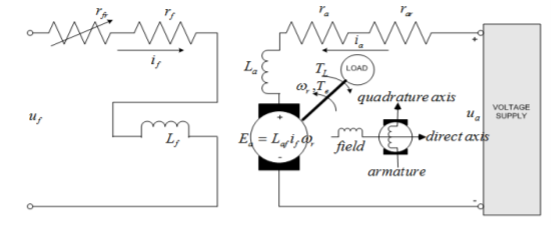
Q9) Explain speed control of separately excited dc motor?
Sol: In Separately excited DC motor field windings are used to excite the field flux. Armature current is supplied to the rotor through brush and commutator. When the motor is excited by a field current if and armature current ia flows, the motor develops a back emf and a torque to balance the load torque at a particular speed. The current if is independent of ia. The armature current has no effect on te field current. The current if is less than ia.

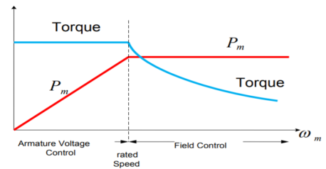
The speed can be controlled by varying voltage in the constant torque region. In the constant power region, field flux should be reduced to achieve speed above the rated speed.

Fig: Armature voltage and field current control
Q10) Explain the working of IM?
Sol: The fundamental principle of induction machine is the creation of rotating and sinusoidally distributed magnetic field in the air gap. Three phase balanced power supply is fed to the three-phase stator winding creates a synchronously rotating magnetic field. Due to relative speed between rotating flux and stationary conductors, an emf is induced. The frequency to induced emf is same as supply frequency.
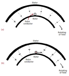
As shown in below fig.a , the stator field is assumed to clockwise. The relative motion of rotor w.r.t stator is anticlockwise. From Right-hand rule, the direction of induced emf in rotor is outwards. By the effect of combined field as shown in fig b the rotor experiences a force tending to rotate it in clockwise direction. Hence rotor rotates in the same direction as the stator field.

The speed of this rotating field is called synchronous speed. If the rotor is initially stationary, its conductors will be subjected to a changing magnetic field, inducing current in the short-circuited rotor at the same frequency. The interaction of air gap flux and rotor mmf produces torque. At synchronous speed rotor cannot have any torque.
Q11) Explain speed control of IM?
Sol: The speed can be controlled by the following methods.
i) Changing stator Pole: This can be done by Multiple stator windings. In stator two windings are provided which are isolated and have different number of poles. By switching we can control the supply to one winding and hence control the speed.
Ii) Supply voltage control: The torque produced is proportional to  . The value of
  is very small and R2 is also constant so T α
 . But E2α V therefore, T α sV2. This equation shows that if supply voltage is decreased the torque also decreases.
Iii) Adding rheostat in the stator: As we already know Tα . The value of
  is very small and E2 is also constant soTα
 . Now if we increase rotor resistance, R2 torque decreases but to supply the same load torque must remain constant. So, we increase slip, which will further result in the decrease in rotor speed. Thus, by adding additional resistance in the rotor circuit, we can decrease the speed of the three-phase induction motor.
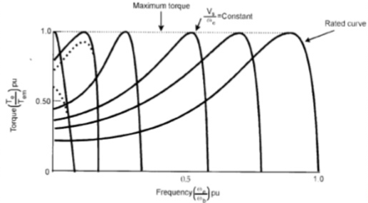
Iv) v/f control: There is no direct relation in the speed and torque. At, full load the motor runs at a speed N. When mechanical load increases motor speed decreases till the motor torque again becomes equal to the load torque.

As long as two torques are equal the motor runs at constant speed. When the supply frequency increases the speed increases and reduces the maximum torque of motor. So,
i) F increases, N increases, Tmax decreases.
Ii) V increases, Tmax increases.
Q12) Explain DOL starter and list its advantages?
Sol: In this induction motor is directly connected to the 3-phase supply. The DOL starter applies full line voltage to the motor terminals.

Fig: D.O.L Starter
If the high input current does not cause any excess voltage drop in circuit than only this starter can be used. The value of armature current in motor is given as
Ia=
The expression for starting torque is given as
Ts starting torque
Tf Full load torque
If per phase rotor current at full load
Is per phase rotor current at starting
sf full load slip
ss starting slip
R2 rotor resistance
Ws synchronous speed of motor
In induction motor torque is given as
T=
The ratio of starting torque to full load torque is given as
 x sf
x sf
The wiring diagram for a DOL starter is shown above. The working principle of a DOL starter begins with the connection to the 3-phase main with the motor. The control circuit is connected to any two phases and energized from them only. When we press the start button, the current flows through magnetizing coil and control circuit also.
The current energises thecontactor coil and leads to close the contacts, and hence 3-phase supply becomes available to the motor. When we stop it, the current discontinues.As the supply to motor breaks the machine stops. . The contactor coil (Magnetizing Coil) gets supply even though we release start button because when we release start button, it will get supply from the primary contacts as illustrated in the diagram of the Direct Online Starter.
The advantages of a DOL starter include:
- Simple and most economical starter.
- More comfortable to design, operate and control.
- Provides nearly full starting torque at starting.
- Easy to understand and troubleshoot.
- DOL starter connects the supply to the delta winding of the motor.