Question Bank
Section – A
Electricity and Power Supply and Electrical Machinery
- Explain the features of power system and power station?
Power generation systems are power generators and related systems that are used in power plants or large-scale facilities. When applying an AC drive and motor to an application; the characteristics of the drives load such as horsepower, torque and speed occur.
Electric power supply system comprises of generating units that produce electricity; high voltage transmission lines that transport electricity over long distances; distribution lines that deliver the electricity to consumers; substations that connect the pieces to each other; and energy control centres that coordinate the operation of the components.
Power station units with full size converters such as type 4 wind turbines and solar PV converter-transformer station units are modelled in the positive-sequence system as a current source. The current is provided by the manufacturer. The positive-sequence shunt impedance is assumed infinite. In the case of unbalanced faults, the negative-sequence impedance depends on the design and control strategies and is given by the manufacturer. The zero-sequence impedance is infinite.
Power station units with full-size converters may be neglected if their contributions are smaller than 5% of the initial short-circuit without these units.
2. Explain distribution and transmission lines?
Transmission
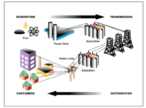
Transmission lines
- Carry electricity across the state
- Transport bulk electricity at high voltages ranging from 60 kV-500 kV
- Are usually supported on tall metal towers, but sometimes on wooden poles
- Have different vegetation standards than distribution lines due to the high voltages they carry
- Are managed using the utility industry’s best-management practice of Wire Zone Border Zone
- Require only low-growing vegetation underneath—typically nothing taller than 10 feet at maturity
Our goal is to achieve a sustainable landscape that supports native plants and natural habitats. Trees near these lines can't be managed by pruning and often must be removed.
Distribution Lines
- Deliver electricity to neighbourhoods and communities over a shorter distance than transmission lines
- Are generally supported by wooden poles and not as high as transmission lines
- Are the final stage of electricity delivery to homes and businesses
- Carry lower voltage electricity that is still powerful enough to cause injury or death
- Trees growing near these lines may be managed with directional pruning, but removal is often best.
3. Explain the difference between AC and DC?
Basis | Alternating current | Direct current |
Definition | The direction of current reverses periodically | The direction of current remains the same |
Causes of flow of current | Rotating of a coil in magnetic filed or rotating uniform magnetic field with stationary coil | Constant magnetic field across the wire |
Frequency | 50 or 60 Hz | Zero |
Direction of flow of electrons | Bidirectional | Unidirectional |
Power factor | Lies between 0 and 1 | Always 1 |
Polarity | It has polarity (+ or -) | Do not have polarity |
Obtained from | Alternators | Generators batttery or cells |
4. Explain voltage, current and resistance?
The three circuit elements are:
- Resistance R
- Capacitance C
- Inductance L
Resistance
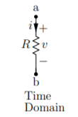
In time domain
v(t) = R . i(t)
i(t) = v(t) /R
Resistance is the static element where v(t) versus i(t) relationship is instantaneous.
Capacitance

Time domain
q(t) = C v(t)
i(t) = dq/dt = C dv/dt
Dv/dt = 1/C i(t)
 = v(t) – vo(t) = 1/C
  ) d
) d 
v(t) = v(to) + 1/C  ) d
) d 
Unlike the resistance for capacitance v(t) versus i(t) relationship at any time t depends on the past as they involve differentials and integrals. This implies that the capacitance is dynamic element. Capacitance stores energy.
Inductance:
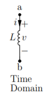
Time domain v(t) = L. Di/dt
Di/dt = 1/L v(t)
 = i(t) – i(to) = 1/L
  ) d
) d
i(t) = i(to) + 1/L  ) d
) d
5. Explain the concept of Electromagnetic Induction?
Electromagnetic Induction is a process in which the conductor is put in a particular position and magnetic field keeps varying or the magnetic field is stationary while the conductor is moving.
This produces voltage or EMF (Electromotive Force) across the electrical conductor.
Michael Faraday discovered Law of Induction in 1830.
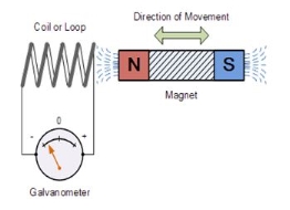
The induction of an electromotive force by motion of theconductor across a magnetic field or by change in magnetic flux in a magnetic field is called ‘Electromagnetic Induction’.
This either happens when a conductor is set in a moving magnetic field (when utilizing AC power source) or when a conductor is always moving in a stationary magnetic field.
6. Explain single phase and three phase emf?
Single Phase EMF:
Alternating voltage may be generated
1) By rotating a coil in a magnetic field
2) By rotating a magnetic field within a stationary coil
The value of voltage generated depends upon
1) No. Of turns in the coil
2) field strength
3) speed Equation of alternating voltage and current.
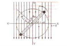
N= No. Of turns in a coil
Φm= Maximum flux when coil coincides with X-axis
ω= angular speed (rad/sec) = 2πf Atθ=ωt,
Φ= flux component ⊥ to the plane =Φm cos ωt
According to the Faraday’s law of electromagnetic induction,
e=-N dɸ/dt = -N d/dt ɸmcoswt = w N ɸm sin wt ………………………………(1)
Now e is maximum value of Em when sin  = sin 90 o =1
That is Em = w N ɸm ……………………………………………………………….(2)
From eq(1) and (2)
e = Em sin wt volts
Now current I at any time in the coil is proportional to the induced emf in the coil .
Hence i = Imsinwt amp
Three phase EMF :
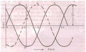
If the 3-coil windings W1, W2 and W3 arranged at 120° apart from each other on the same axis are rotated, then the emf induced in each of them will have a phase difference of 120°. In other words, if the emf (or current) in one winding (w1) has a phase of 0°, then the second winding (w2) has a phase of 120° and the third (w3) has a phase of 240°.
Star (Y) connection:-
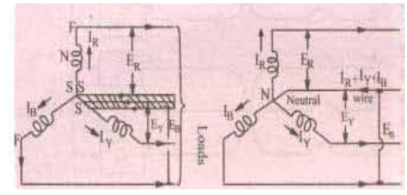
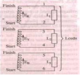
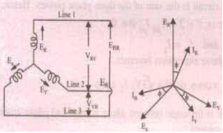
Phasor diagram:-
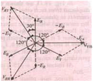
Here, ER, EY, EB are phase voltages and VRY, VYB, VBR are line voltages
VRY =  E R2 + EY2 + 2 ER EY cos 60 0
=  E R2 + ER2 + 2 ERER cos 60 0
= √ 3 ER
Hence,
• Line voltage =√3 x phase voltage
• Line current = phase current
• Line voltages are also 120° apart
• Line voltage are 30° ahead of respective phase voltages
• The angle between line voltage and line current is (30°+Φ)
Power: Total power = 3 x phase power
=3 x Vph x I ph x cosΦ
=√3 VL IL cosΦ
Φ is the angle between phase voltage and current
7. Explain three phase star and delta connection?
Star to delta conversion to final equivalent resistance
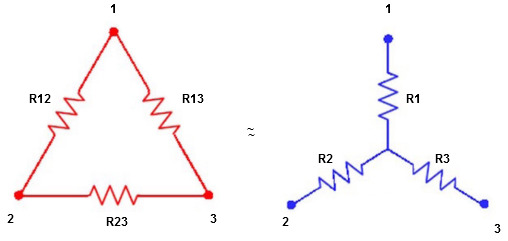
We know that (from delta to star conversion)
R1 =  …….①
…….①
R2 =  …..②
…..②
R1 =  ……③
……③
Multiply ① X ② L.H.S and R.H.S
R1 R2 = …….④ where
Similarly multiply ② X ③
R2 R3 = …….⑤
…….⑤
And ③ X①
R1 R3 = …….⑥
…….⑥
Now add equation ④, ⑤, and ⑥ L.H.S and R.H.S


 ……refer eq. ②
 =
=  +
+  +
+ 
 =
=  +
+ 

(Delta) star star
Similarly R23 = R2+R3 + 
R23 = R1+R2 + 
- Delta to Star Conversion to Find (Req.)
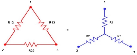
- Equivalent resistance between ① and ②
Delta Star
Star
= R12// (R23 + R13) =R1 + R2
= 
 = R1 + R2
= 

Here let R = R12 + R23 + R13
- Similarly we can find Req. Between 2 and 3
= 
 R2 + R3
- Similarly we can find req. Between 1 and 3

 R1 + R3
Now the 3 equations after equating L.H.S. And R.H.S
R1 + R2 =  …….①
…….①
R2 + R3 =  ……②
……②
R1 + R3 =  …..③
…..③
Now subtract ② and ① on L.H.S. And R.H.S
R2+ R3 – R1 – R2 = 
 R3 – R1 =
  …..④
…..④
Now add equation ④ and ③
R3 – R1 + R1 + R3 = 
2R3 = 

Similarly R1 = 
And R2 = R23 R12/R where R = R12 + R23 + R13
Ie star equivalent from delta network is ratio of product of adjacent branches in delta to the addition of all branches in delta.
8. Explain voltage and current relations?
- The relation between line value and phase value of voltage and current for a balance (
 ) delta connected inductive load
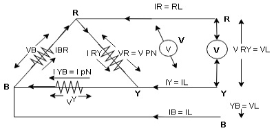
Consider a 3 Ø balance delta connected inductive load
- Line values
Line voltage = VRY = VYB = VBR = VL
Line current = IR = IY = IB = IL
Phase value
Phase voltage = VRN = VYN = VBN = Vph
Phase current = VRN = VYN = VBN = Vph
- Since for a balance delta connected load the voltage measured in line and phase is same because their measuring points are same
 for balance delta connected load VL = Vph
 VRV = VYB = VBR = VR = VY = VB = VL = VPh
- Since the line current differ from phase current we can relate the line and phase values of current as follows
- Apply KCL at node R
IR + IRY= IRY
 IR = IRY - IRY … ….①

Line phase
Similarly apply KCL at node Y
IY + IYB = IRY … ….②
Apply KCL at node B
IB + IBR = IYB … ….③
PPh =VPhIPh Cos Ø
For 3 Ø total power is
PT= 3 VPhIPh Cos Ø …….①
For star
VL and IL = IPh (replace in ①)
 PT = 3
  IL Cos Ø
 PT = 3
  VL IL Cos Ø – watts
For delta
VL =VPhand IL =  (replace in ①)
PT = 3VL
= 3VL  Cos Ø
Cos Ø
 PT
PT VLIL Cos Ø – watts
Total average power
P =  VLIL Cos Ø – for ʎ and
  load
load
K (watts)
Total reactive power
Q =  VLIL Sin Ø – for star
  delta load
K (VAR)
Total Apparent power
S =  VL IL – for star
  delta load
K (VA)
- Power triangle
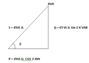
- Relation between power
In star and power in delta
Consider a star connected balance load with per phase impedance ZPh
We know that for
VL = VPhandVL=  VPh
VPh
Now IPh = 
 VL = =
And VPh=
 IL =
IL = ……①
……①
Pʎ =  VL IL Cos Ø ……②
Replacing ① in ② value of IL
 Pʎ =
Pʎ =  VL IL
VL IL  Cos Ø
Cos Ø
 Pʎ =
Pʎ =  ….A
….A
- Now for delta
IPh =
 IPh = =
And IL = IPh
IPh
 IL =
IL = X
X  …..①
…..①
P =
=  VL IL Cos Ø ……②
Replacing ② in ① value of IL
P =
=  Cos Ø
Cos Ø
 P
P =
=  …..B
…..B

Pʎ from …A
 …..C
…..C
 =
=  P
P
We can conclude that power in delta is 3 time power in star from …C
Or
Power in star is  time power in delta from ….D
- Step to solve numerical
- Calculate VPh from the given value of VL by relation
For star VPh = 
For delta VPh= VL
2. Calculate IPh using formula
IPh = 
3. Calculate IL using relation
IL = IPh - for star
IL = IPh - for delta
4. Calculate P by formula (active power)
P =  VL IL Cos Ø – watts
5. Calculate Q by formula (reactive power)
Q =  VL IL Sin Ø – VAR
6. Calculate S by formula (Apparent power)
S =  VL IL– VA
9. What is a transformer explain its working?
A transformer is defined as a static device which helps in the transformation of electric power in one circuit to electric power of the same frequency in another circuit. The voltage can be raised or lowered in a circuit, but with a proportional increase or decrease in the current ratings.
Working Principle
The main principle of operation of a transformer is mutual inductance between two circuits linked by a common magnetic flux.
A basic transformer consists of two coils that are electrically separate and inductive but are magnetically linked through a path of reluctance.
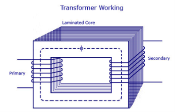
Working
The electrical transformer has primary and secondary windings. The core laminations are joined in the form of strips in between the strips and there are some narrow gaps right through the cross-section of the core.
These staggered joints are said to be ‘imbricated’. Both the coils have high mutual inductance.
A mutual electro-motive force is induced in the transformer from the alternating flux that is set up in the laminated core, due to the coil that is connected to a source of alternating voltage.
Most of the alternating flux developed by this coil is linked with the other coil and thus produces the mutual induced electro-motive force. The so produced electro-motive force is because of Faraday’s laws of Electromagnetic Induction as
e=M*dI/dt
If the second coil circuit is closed, current flows in it and thus electrical energy is transferred magnetically from the first to the second coil.
The alternating current supply is given to the first coil is called as the primary winding. The energy is drawn out from the second coil is secondary winding.
10. Explain the types of transformers ?
Core-type Transformer
In this type of construction, only half of the windings are wound cylindrically around each leg of a transformer to enhance magnetic coupling as shown in the figure below.
This type of construction ensures that magnetic lines of force flow across both the windings simultaneously. The main disadvantage of the core-type transformer is the leakage flux that occurs due to the flow of a small proportion of magnetic lines of force outside the core.
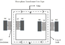
Core-type-transformer
Shell-type Transformer
In this type of transformer construction, the primary and secondary windings are positioned cylindrically on the center limb resulting in twice the cross-sectional area than the outer limbs. There are two closed magnetic paths in this type of construction and the outer limb has the magnetic flux ɸ/2 flowing. Shell type transformer overcomes leakage flux, reduces core losses and increases efficiency.
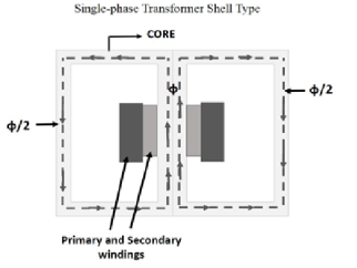
single-phase-transformer-shell-type
11. Explain the type of losses in transformer?
The types of losses in transformer are:
Iron Losses in a Transformer
Iron losses occur through the alternating flux within the transformer’s core. Once this loss occurs within the core then it is called core loss. This kind of loss mainly depends on the material’s magnetic properties within the core of the transformer. The core in the transformer can be made with iron, so these are called iron losses. This type of loss can be categorized into two types like hysteresis as well as eddy current.
Hysteresis Loss
This kind of loss mainly occurs when the alternating current is applied to the core of the transformer then the magnetic field will be reversed. This loss mainly depends on the core material used in the transformer.
To reduce this losshigh-grade core material can be used. CRGO- Cold rolled grain -oriented Si steel is used commonly like the core of the transformer so that Hysteresis loss can be reduced.
This loss can be represented by using the following equation.
Ph = KhfBx m
Where
‘kh’ is the constant that depends on the quality & volume of the core material in the transformer
‘Bm’ is the highest flux density within the core
‘f’ is the alternating flux frequency otherwise supply
‘x’ is the constant of the Steinmetz and the value of this constant mainly changes from 1.5 to 2.5.
Eddy Current Loss
Once the flux is connected to a closed circuit, then an e.m.f can be induced within the circuit and there is a supply in the circuit. The flow of current value mainly depends on the sum of an e.m.f and resistance in the region of the circuit.
The core of the transformer can be designed with a conducting material. The flow of current in the emf can be supplied within the body of the material. This flow of current is known as eddy current. This current will occur once the conductor experiences an altering magnetic field.
When these currents are not accountable for doing any functional task, then it generates a loss within the magnetic material. Hence it is called as an Eddy Current Loss. This loss can be reduced by designing the core using slight laminations.
The eddy current equation can be derived by using the following equation.
Pe = KeBm2t2f2V watts
Where,
‘Ke’ is the co-efficient of eddy current. This value mainly depends on the magnetic material’s nature like resistivity and volume of the core material & the width of laminations
‘Bm’ is the highest rate of flux density in wb/m2
‘T’ is the width of lamination within meters
‘F’ is the frequency of reverse of the magnetic field measured in Hz
‘V ‘is the amount of magnetic material in m3
Copper Loss
Copper losses occur because of the Ohmic resistance in the windings of the transformer. If the primary and secondary windings of the transformer are I1 and I2, then the resistance of these windings is R1 & R2. So, the copper losses that occurred in the windings are I12R1 &I22R2 respectively. So, the entire copper loss will be
Pc = I12R1 + I22R2
These losses also called variable or ohmic losses because these losses will change based on the load.
Stray Loss
These types of losses in a transformer occur because of the occurrence of the leakage field. As compared with copper and iron losses, the percentage of stray losses are less, so these losses can be neglected.
Dielectric Loss
This loss mainly occurs within the oil of the transformer. Here oil is an insulating material. Once the oil in the transformer gets deteriorates otherwise when oil quality diminishes then the transformer’s efficiency will be affected.
12. Explain its voltage regulation and efficiency?
Efficiency of Transformer
It is the ratio of output power and input power. The efficiency can be calculated by the following formula.
Efficiency = Output Power / Input Power.
When a transformer is highly efficient, then its input and output have almost the same value, and therefore it is not practical to calculate the efficiency of the transformer by using the above formula. But to find its efficiency, the following formula is better to use
Efficiency = (Input – Losses) / Input => 1 – (Losses /Iinput).
Let copper loss is I2R1 whereas iron loss is Wi
Efficiency = 1-Losses/Input
= 1-I12R1+Wi/V1I1CosΦ1
Ƞ = 1-(I1R1/V1CosΦ1) –Wi/ V1I1CosΦ1
Differentiate the above equation with respect to ‘I1’
d Ƞ/dI1= 0- (R1/V1CosΦ1) + Wi/V1I12 CosΦ1
‘Ƞ’ is maximum at d Ƞ/dI1 =0
Therefore, efficiency ‘Ƞ’ will be maximum at
R1/V1CosΦ1 = Wi/V1I12 CosΦ1
I12R1/ V1I12 CosΦ1 = Wi/V1I12 CosΦ1
I12R1 = Wi
Therefore, the transformer efficiency can be highest when iron and copper losses are equal.
So, Copper loss = Iron loss.
Voltage Regulation:
Let’s say an electrical power transformer is open circuited that is the load is not connected to the secondary terminals.
In this situation, the secondary terminal voltage of the transformer will be its secondary induced emf E2.
Whenever a full load is connected to the secondary terminals of the transformer, rated current I2 flows through the secondary circuit and voltage drop comes into picture.
At this situation, primary winding will also draw equivalent full load current from source.
The voltage drop in the secondary is I2Z2 where Z2 is the secondary impedance of the transformer.
At this loading condition if we measure the voltage between secondary terminals, voltage V2 across load terminals is less than no load secondary voltage E2 and this is because of I2Z2 voltage drop in the transformer.
The equation for the voltage regulation of transformer, represented in percentage is
Voltage regulation (᷁ ) = E2 – V2 / V2 x 100%
13. Explain open circuit and short circuit of transformer?
Open circuit:
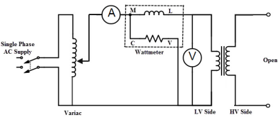
The purpose of the open-circuit test is to determine the no-load current and losses of the transformer. This test is performed on the primary winding of the transformer. The wattmeter, ammeter and the voltage are connected to their primary winding. The nominal rated voltage is supplied to their primary winding with the help of the ac source.
The secondary winding of the transformer is kept open, and the voltmeter is connected to their terminal. This voltmeter measures the secondary induced voltage. As the secondary of the transformer is open, thus no-load current flows through the primary winding.
The copper loss occurs only on the primary winding of the transformer because the secondary winding is open. The reading of the wattmeter only represents the core and iron losses.
Let,
- W0 – wattmeter reading
- V1 – voltmeter reading
- I0 – ammeter reading
Then the iron loss of the transformer Pi = W0 and
Wo = Vo Io cos ɸo ………………………………..(1)
The no-load power factor is
Cos ɸo = Wo/ V1 Io
Working component Iw is
Iw = Wo/V1 ………………………………………….(2)
Putting the value of W0 from the equation (1) in equation (2) the value of the working component is
Iw = Io cos ɸo
The magnetizing component is
Im =  Io 2 – Iw 2
No-load parameters are given below:
Equivalent exciting resistance is
Ro = V1/Iw
Equivalent exciting reactance is
Xo = V1/Im
The phasor diagram of the transformer at no load or when an open circuit test is performed is shown below
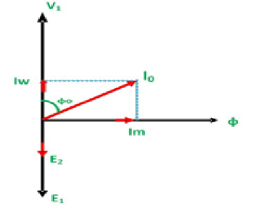
Phasor Diagram
The iron losses measured by the open circuit test is used for calculating the efficiency of the transformer.
Short circuit test
The short circuit test is performed on the secondary or high voltage winding of the transformer. The measuring instrument like wattmeter, voltmeter and ammeter are connected to the high voltage winding of the transformer. Their primary winding is short-circuited by the help of thick strip or ammeter which is connected to its terminal.
The low voltage source is connected across the secondary winding because of which the full load current flows from both the secondary and the primary winding of the transformer. The full load current is measured by the ammeter connected across their secondary winding.
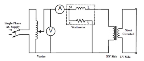
The iron loss of the transformer depends on the flux. It is less occur in the short circuit test because of the low value of flux. The reading of the wattmeter only determines the copper loss occurred, in their windings. The voltmeter measures the voltage applied to their high voltage winding. The secondary current induces in the transformer because of the applied voltage.
Let,
- Wc – Wattmeter reading
- V2sc – voltmeter reading
- I2sc – ammeter reading
Then the full load copper loss of the transformer is given by
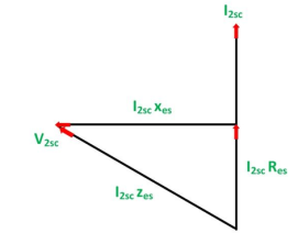
Pc = (I2fl/I2sc) 2Wc and I2 2sc Res = Wc
Equivalent resistance referred to the secondary side is
Res = Wc/ I 2sc
The phasor diagram of the short circuit test of the transformer is shown below
14. What is an autotransformer?
An autotransformer is a transformer with a single winding split into primary and secondary sections. It operates on the same principle as any other transformer where the magnetic flux resulting from time varying primary current induces time varying current in the secondary winding. The integrated primary/secondary winding of an autotransformer is typically tapped at different points along the winding to allow the output/secondary voltage to be varied in discrete steps at various percentages of the input or primary voltage.
A schematic representation of a typical auto transformer with six discrete taps is shown below.
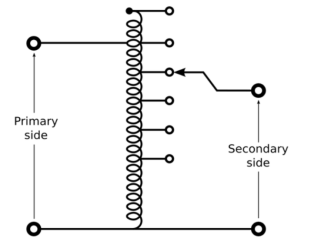
In two-winding transformer the primary and the secondary portions of the single winding autotransformer are wound on the same core.
If the adjustable secondary tap is positioned above the primary/input winding maximum output/secondary voltage is greater than 100% of input/primary voltage. Tap positions below te primary/input winding will result in an output/secondary voltage less than 100% of the primary/input voltage.
Applications
The applications of auto transformers are :
- Reduced voltage starter for induction motor
- Starting gear for certain types of fluorescent light fitures
- Booster at the end of long transmission line to compensate for line losses.
- Multi-tap type feeding the primary of plating rectifier transformer to enable rectifier output control.