Question Bank
Section D
- Explain the working principle of DC motor ?
Working Principle of DC motor:
A DC motor is an electrical machine which converts electrical energy into mechanical energy. The basic working principle of the DC motor is that whenever a current carrying conductor places in the magnetic field, it experiences a mechanical force.
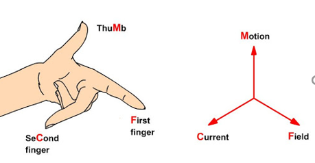
If we stretch the first finger, second finger and thumb of our left hand to be perpendicular to each other, and first finger represents the direction of the magnetic field, the second finger represents the direction of the current, then the thumb represents the direction of the force experienced by the current carrying conductor.
F = BIL Newtons
Where,
B = magnetic flux density,
I = current and
L = length of the conductor within the magnetic field.
When armature winding is connected to a DC supply, an electric current sets up in the winding. Permanent magnets or field winding (electromagnetism) provides the magnetic field.
In this case, current carrying armature conductors experience a force due to the magnetic field, according to the principle stated above.
The commutator is made segmented to achieve unidirectional torque. Otherwise, the direction of force would have reversed every time when the direction of movement of the conductor is reversed in the magnetic field.
2. Explain the Working Principle of AC motor?
The motor that converts the alternating current into mechanical power by using an electromagnetic induction phenomenon is called an AC motor. This motor is driven by an alternating current. The stator and the rotor are the two most important parts of the AC motors.
The stator is the stationary part of the motor, and the rotor is the rotating part of the motor. The AC motor may be single phase or three- phase.
The three phase AC motors are mostly applied in the industry for bulk power conversion from electrical to mechanical. For small power conversion, the single- phase AC motors are mostly used.
The single- phase AC motor is nearly small,and it provides a variety of services in the home, office, business concerns, factories, etc.
Almost all the domestic appliances such as refrigerators, fans, washing machine, hair dryers, mixers, etc., use single phase AC motor.
Construction of DC Motor:

There are two main parts of DC motor.
- Armature
- Stator
The rotating part is the armature, and the stator is stationary part. The armature coil is connected to the DC supply.
The armature coil consists the commutators and brushes. The commutator converts the AC induces in the armature into DC and brushes transfer the current from rotating part of the motor to the stationary external load. The armature places between the north and south pole of the permanent or electromagnet.
3. Explain the construction of AC motor?
The AC motor consists of three basic parts: the stator, rotor, and enclosure.
The stator and the rotor are electrical circuits that work like electromagnets. The stator is the electrical part of the motor that does not move. For a NEMA motor, the stator core is constructed with several hundred fine laminations.
Stator laminations are arranged to form a hollow cylinder. Each slot of the stator core receives a coil of insulated wire. An electromagnet is formed by each group of coils and the surrounding steel core. Motors operate thanks to electromagnetism. The power source is directly connected to the stator windings.
Within the electromagnetic circuit, the rotor is the part that rotates. The squirrel cage rotor is the most common type of rotor. The rotor is made up of a stack of steel laminations that include uniformly spaced conductor bars surrounding the perimeter.
The rotor core is formed by the stacked laminations. Aluminium is die cast in the slots of the rotor core to form a series of conductors around the circumference of the rotor. The conductor bars are electrically and mechanically fused with end rings. Finally, the core of the rotor is mounted on a steel shaft.
The enclosure is made of a frame, or yoke, and two end brackets, also called bearing housings. The stator is installed inside the frame. The rotor sits inside the stator but separated by a slight air gap so that they donot have any direct physical contact with each other. The purpose of the enclosure is to protect the operating and electrical parts of the motor from the harsh environment in which they operate.
The bearings that are mounted on the shaft support the rotor, which enables it to turn. A fan is installed on the shaft for when the motor needs to be cooled down.
4. Explain the types of DC motors?
D.C. Motors can be classified into three types according to the connection of field windings to the armature windings:
1. Shunt wound motor
2. Series wound motor
3. Compound wound motor
Shunt wound motor
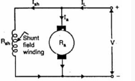
Here the field windings are connected in parallel with the armature.
For constant applied voltage, the field current is constant.
The speed of the shunt wound makes it almost constant as the flux and back emf are constant. Therefore, it is also considered constant speed machine.
Series wound motor
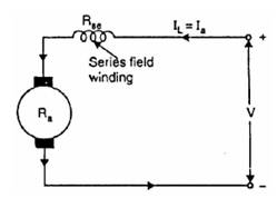
Since the field winding and armature are connected in series.
Ifield = I armature
One of the characteristics and advantage of D.C. Motor is that as the motor is loaded heavily, the speed of the motor automatically gets reduced.
Compound motor
In compound wound motor the field (pole) winding comprises of two windings:
a. Shunt field winding
b. Series field windings
The field windings connected in series and shunt this produce the resultant flux to drive the motor. D.C. Compound motor is a combination of the series and the shunt motor. The series field winding is connected in series with the armature and a shunt field is in parallel with the armature.
The combination of series and shunt winding allow the motor to have the torque characteristics of the series motor and the regulated speed characteristics of the shunt motor.

5. Explain the working of single phase?
A Single-Phase Induction Motor consists of a singlephase winding which is mounted on the stator of the motor and a cage winding placed on the rotor. A pulsating magnetic field is produced, when the stator winding of the single-phase induction motor shown below is energized by a singlephase supply.
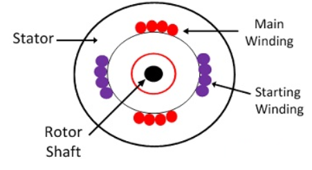
The word Pulsating means that the field builds up in one direction falls to zero and then builds up in the opposite direction. Under these conditions, the rotor of an induction motor does not rotate. Hence, a single-phase induction motor is not self-starting. It requires some special starting means.
If the 1 phase stator winding is excited and the rotor of the motor is rotated by an auxiliary means and the starting device is then removed, the motor continues to rotate in the direction in which it is started.
The performance of the single-phase induction motor is analysed by the two theories. One is known as the Double Revolving Field Theory, and the other is Cross Field Theory. Both the theories are similar and explain the reason to produce torque when the rotor is rotating.
Double Revolving Field Theory of Single- Phase Induction Motor
The double revolving field theory of a single- phase induction motor states that a pulsating magnetic field is resolved into two rotating magnetic fields. They are equal in magnitude but opposite in directions. The induction motor responds to each of the magnetic fields separately. The net torque in the motor is equal to the sum of the torque due to each of the two magnetic fields.
The equation for an alternating magnetic field is given as
b(α) = β max sin w t cos α -----------------------(1)
Where βmax is the maximum value of the sinusoidally distributed air gap flux density produced by a properly distributed stator winding carrying an alternating current of the frequency ω, and α is the space displacement angle measured from the axis of the stator winding.
SinAcosB = ½ sin(A-B) + ½ sin(A+B)
So, the equation (1) becomes
b(α) =1/2 β max sin (w t- α) + ½ β max sin (w t+ α) ------------(2)
The first term of the right-hand side of the equation (2) represents the revolving field moving in the positive α direction. It is known as a Forward Rotating field. Similarly, the second term shows the revolving field moving in the negative α direction and is known as the Backward Rotating field.
The direction in which the single -phase motor is started initially is known as the positive direction. Both the revolving field rotates at the synchronous speed. ωs = 2πf in the opposite direction. Thus, the pulsating magnetic field is resolved into two rotating magnetic fields. Both are equal in magnitude and opposite in direction but at the same frequency.
At the standstill condition, the induced voltages are equal and opposite as a result; the two torques are also equal and opposite. Thus, the net torque is zero and, therefore, a single- phase induction motor has no starting torque.
6. Explain the working of three phase induction motor?
A 3- phase induction motor consists of two major parts:
- A stator
- A rotor
The stator of three phase induction motor is made up of numbers of slots to construct a 3- phase winding circuit when we connect with 3- phase AC source. We arrange the three-phase winding in such a manner in the slots that they produce one rotating magnetic field when we switch on the three-phase AC supply source.
The rotor of three phase induction motor consists of a cylindrical laminated core with parallel slots that can carry conductors. The conductors are heavy copper or aluminium bars fitted in each slot and short-circuited by the end rings. The slots are not exactly made parallel to the axis of the shaft but are slotted a little skewed because this arrangement reduces magnetic humming noise and can avoid stalling of the motor.
The stator of the motor consists of overlapping winding offset by an electrical angle of 120o. When we connect the primary winding, or the stator to a 3 phase AC source, it establishes rotating magnetic field which rotates at the synchronous speed.
Thus, from the working principle of three phase induction motor, it may be observed that the rotor speed should not reach the synchronous speed produced by the stator. If the speeds become equal, there would be no such relative speed, so no emf induced in the rotor, and no current would be flowing, and therefore no torque would be generated. Consequently, the rotor cannot reach the synchronous speed. The difference between the stator (synchronous speed) and rotor speeds is called the slip.
7. Explain three phase synchronous motor?

A 3-phase synchronous motor as shown in the figure below generates an electrically rotating field in stator. Such motors are not self-starting if started from a fixed frequency power source such as 50 or 60 Hz as found in an industrial setting.
Large industrial synchronous motors are more efficient than induction motors. They are used when constant speed is required. Having a leading power factor, they can correct the AC line for a lagging power factor.
The three phases of stator excitation add vectorially to produce a single resultant magnetic field which rotates f/2n times per second, where f is the power line frequency, 50 or 60 Hz for industrial power line operated motors. The number of poles is n. For rotor speed in rpm, multiply by 60.
S = f120/n
Where:
S = rotor speed in rpm
f = AC line frequency
n = number of poles per phase
The 3-phase 4-pole (per phase) synchronous motor will rotate at 1800 rpm with 60 Hz power or 1500 rpm with 50 Hz power. If the coils are energized one at a time in the sequence φ-1, φ-2, φ-3, the rotor should point to the corresponding poles in turn.
Since the sine waves actually overlap, the resultant field will rotate, not in steps, but smoothly. For example, when the φ-1 and φ-2 sine waves coincide, the field will be at a peak pointing between these poles.
The rotor with multiple magnet poles (below right) is used in any efficient motor driving a substantial load. These will be slip ring fed electromagnets in large industrial motors. Large industrial synchronous motors are self-started by embedded squirrel cage conductors in the armature, acting as an induction motor.
The electromagnetic armature is only energized after the rotor is brought up to near synchronous speed.
8. Explain protection device ?
The circuit protection device is an electrical device used for preventing an unnecessary amount of current which is otherwise a short circuit.
To ensure the highest security, protection devices offers total range of protection devices for circuits such as a fuse, circuit breakers, RCCB, gas discharge tubes, thyristors and more.
9. Explain Fuse, MCB, Relay and LCB?
SWITCH FUSE UNIT (SFU)
It is Switched Fuse Unit. It has one switch unit and one fuse unit.
When we operate the breaker, the contacts will get close through switch and then the supply will passes through the fuse unit to the output.
Whereas in Fuse Switch Unit there is no separate switch and fuse unit. There is only fuse unit which act itself as a switch.
When we operate the fuse unit will close the input and output of the breaker.
MCB
- A miniature circuit breaker automatically switches off electrical circuit during abnormal condition of the network means in over- load condition as well as faulty condition.
- Nowadays we use an MCB in low voltage electrical network instead of fuse. The fuse may not sense it but the miniature circuit breaker does it in a more reliable way. MCB is much more sensitive to over current than fuse.
- Handling a MCB is electrically safer than a fuse. Quick restoration of supply is possible in case of fuse as because fuses must be re- wireable or replaced for restoring the supply. Restoration is easily possible by just switching it ON.
ELCB
- Early earth leakage circuit breakers are voltage detecting devices, which are now switched by current sensing devices (RCD/RCCB).
- Generally, the current sensing devices termed as RCCB and voltage detecting devices named as Earth Leakage Circuit Breaker (ELCB).
- An ECLB is one kind of safety device used for installing an electrical device with high earth impedance to avoid shock. These devices identify small stray voltages of the electrical device on the metal enclosures and intrude the circuit if a dangerous voltage is identified.
- The main purpose of Earth leakage circuit breaker (ECLB) is to stop damage to humans & animals due to electric shock.
- An ELCB is a specific type of latching relay that has a structure’s incoming mains power associated through its switching contacts so that the circuit breaker detaches the power in an unsafe condition.
- The ELCB notices fault currents of human or animal to the earth wire in the connection it guards. If ample voltage seems across the ELCB’s sense coil, it will turn off the power, and remain off until manually rearrange. A voltage sensing ELCB doesn’t detect fault currents from human or animal to the earth.
Relays
A relay is automatic device which senses an abnormal condition of electrical circuit and closes its contacts. These contacts in turns close and complete the circuit breaker trip coil circuit hence make the circuit breaker tripped for disconnecting the faulty portion of the electrical circuit from rest of the healthy circuit.
10. Explain the need of earthing?
Earthing is necessary for all domestic,commercial and industrial installation to safeguard the operator,tall buildings and machinery against lightning.
Metal body of all the electrical appliances,equipment and machinery,the earth points of all three-pin sockets and the body of the energy meter are connected to earth through a thick G.I. Wire.
Whenever a live wire comes in contact with the body of the appliance,it is directly connected to earth the grounding wire and hence the body voltage comes to zero.Therefore the operator does not get any shock,when he comes in contact with body of the appliance.
The high voltage included during lightning is discharged to earth through grounding wire and thereby building and machinery are protected.
11. Explain the types of earthing?
Neutral Earthing
In neutral earthing, the neutral of the system is directly connected to earth by the help of GI wire. The neutral earthing is also called system earthing. Such type of earthing is mostly provided to the system which has star winding. For example, the neutral earthing is provided in the generator, transformer, motor etc.
Equipment Earthing
Such type of earthing is provided to the electrical equipment. The non-current carrying part of the equipment like their metallic frame is connected to the earth by the help of the conducting wire. If any fault occurs in the apparatus, the short-circuit current to pass the earth by the help of wire. Thus, protect the system from damage.
12. What is grounding?
Grounding can be defined as a connection, whether intentional or accidental, between an electrical circuit or equipment and earth or to some conducting body that serves in place of earth. Hence, one can conclude that grounding is nothing but connection to earth or to a conductor that serves as earth. Going by this definition, a connection between a circuit and its 0V reference can also be considered as grounding, while earthing can be considered as a case of grounding where the ground is essentially planet Earth.
13. What is cable?
The cable that is used for the transmission and distribution of electrical energy is called the electrical power cable. It is used for the transmission of high voltages in places wherein overhead lines are impractical to use.
The power cable is made of three principal components, namely, conductor, dielectric, and sheath. The conducting direction for the current inside the cable is provided with the aid of the conductor. The insulation or dielectric withstands the carrier voltage and isolates the stay conductor with other objects.
Cable :
Non-Metallic Sheathed Cable
Underground Feeder Cable :
Metallic Sheathed Cable :
Multi-Conductor Cable :
Coaxial Cable :
Unshielded Twisted Pair Cable
Ribbon Cable
Direct-Buried Cable
Twin-Lead Cable
Twin axial Cable
Paired Cable
Twisted Pair
14. Explain LT and HT cables?
L.T. (Low Tension) cables are widely used for low voltage (1.1kV). These cables must have proper protection from water, corrosion and mechanical strength must be high. These cables must sustain a longer life for that various protections are required.
In this type of cables: –
- The electrostatic stresses are less.
- The thermal conductivity is also very less.

The conductors in the cable are surrounded by lead sheath with an insulating layer of paper insulation.
Compounded fibrous material is surrounded around the lead sheath. The fibrous compounded material & wire armored is covered around the cable.
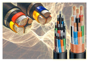
Conductor
The conductor of power cables is made from EC grade aluminium or annealed electrolytic copper. All conductors conform to IS: 8130. The conductors are solid / stranded / compact circular / sector shaped.
Insulation
In PVC Power Cables the conductor is insulated with the poly vinyl chloride covering over conductor as insulation by extrusion process and In XLPE Power Cables cross linked polyethylene covering as insulation over conductor by extrusion process.
For identification of cores the following colour scheme is adopted.
1 Core | Red, Black, Yellow, Blue |
2 Cores | Red & Black |
3 Cores | Red, Yellow & Blue |
3.5 & 4 Cores | Red, Yellow, Blue & Black (Reduced Neutral Core in case of 3.5 Core |
HT cables
High Tension(HT) supply is applicable for bulk power purchasers who need 11 kilo-volts or above. They are different from low voltage cables that they have additional internal layers in the insulation jacket to control the electric field around the conductor. Often a high voltage cable has a metallic shield layer over the insulation designed to equalize the dielectric stress on the insulation layer. Longest high voltage cables are often used as submarine cables under the ocean for power transmission.
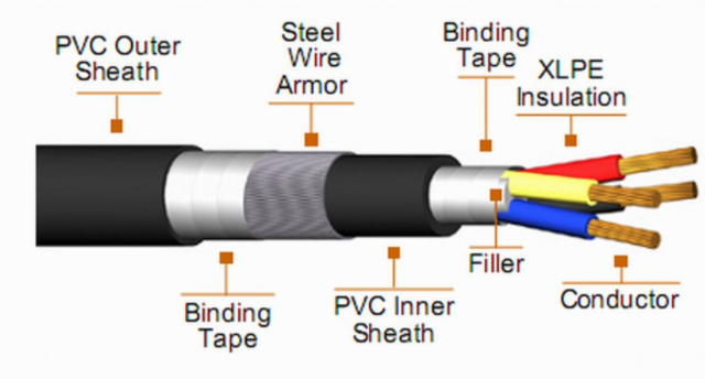
It consists of one or more conductors, insulation, and a protective jacket. Cables for power distribution of 10KV or higher may be insulated with oil and paper, for higher voltages it may be kept under pressure to prevent the formation of voids. Most high voltage cables for power transmission are insulated with a sheath of XLPE(cross-linked polyethylene). Terminals of high-voltage cables must manage the electric fields at the ends.
High tension cables comprise of XLPE which is used to increase the abrasion resistance and environmental stress cracking resistance. These cables have an advantage of higher current carrying capacity as it comprises of higher permissible continuous conductor temperature which is up to 90° C.