UNIT 4
1. Explain magnetic circuit concept.
It involves the interaction of magnetic field and current carrying conductor placed in it. The operation sequence is as follow
2. Development of individual field
3. Interaction of two magnetic fields
4. Force exerted on the conduction
- Development of individual field

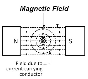
- Let a straight conductor is placed in the magnetic field produced by permanent magnet.
- Let current flowing through the conductor is out of the plane of the paper.
- The magnetic field produced by conductor is shown above
2. Interaction of two magnetic field

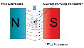
At the top flux lines produced by the magnet and conductor are in opposite direction to each other and hence cancel each other.
At the bottom individual fields are in same direction they will add each other.
3. Force excreted on the conductor

The lines of force on the bottom exert a force on the conductor in the upward direction as shown above.
Hence mechanical force is exerted on the conductor from high flux line area towards the low flux line area (top).
2. Explain types of winding.
- There a 2 types of winding
- Concentric or cylindrical
- Sandwiched type
- Cylindrical
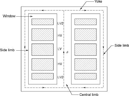
L.V. = low voltage H.V. = high voltage are mounted on same limb to minimum leakage .

L.V. Winding placed inside and H.V. Winding placed outside with (proper insulation between the winding as it is easy to insulated L.V. Winding) than H.V. Winding.
2. Sandwiched

The H.V. And L.V. Winding are divided into no. Of small coils and there small windings are interleaved.
(the top and bottom winding are L.V. Coils because they are close to core)
- Transformer tank: wholes assembly of winding and core placed inside the Transformer tank (sheet metal tank) which is filled with Transformer oil or insulating oil which acts as an (insulator or coolant) MCQ
- Transformer oil: (The function of oil is to remove efficiently the heat generated in core and in winding)
- Moisture should not be allowed which creeps the insulation which achieved by closed Transformer tank.
(To increase cooling surface are tubes or fins are provided)
- Conservator tank: above tank T/F tank there is one small tank in which same empty space is always provided above the oil level. (this space is required for oil to expand or contract due to temperature change) MCQ
However during contraction outside air can have moisture which will deteriorate the insulating properly of oil.
- Breather: the air goes in or out through the breather (To reduce the moisture content of their air . Same drying agents such as (silica gel or) calcium chloride) is used in the breather (The dust particles present in air are also removed by breather)
- Buccholz Relay: (for incipient (slowly increasing) faults
There is pipe connecting rain tank and conservator. On the pipe a protective device called Buccholz Relay is mounted.
When the Transformer is about to be faulty and draw range current the oil becomes very hot and decompose.
During this process different types of gases are liberated. (The Bucchoz Relay get operated by these gases) and gives an alarm to the operator. ɡȴ the fault continues to persist then there lay will trip off main circuit breaker to protect the Transformer.
- Explosion Vent:
An explosion Vent or relief value is the bent-up pipe filled on the main tank.
(The explosion vent consist of aluminium of oil ) when the T/F becomes faulty the cooling oil get decomposed and various types of gases are liberated
(ɡȴ the gas pressure exodus certain level then the aluminium of oil (diagram) in explosion vent will burst) to release pressure. They will save main tank from getting damaged.
3. Derive E = 4.44 F Ø m N2
As primary winding excited by a sinusoidal alternating voltage an alternating current flow in the winding producing an alternating varying flux Ø
Ø = Øm sin wt
As per Faradays Law of Electromagnetic Induction emf E1 is induced
E1 = N1
E1 = N1 (Ø Sin wt)
= - N1Øm w Cos wt
Sin (90-wt)
= - Sin (wt-90)
 E1 = N1Øm w Sin (wt-90)
 w =
w = 
 E1 =
E1 =  N1 Ø m Sin (wt-90)
Max value of E1 = E max
Is when Sin (wt-90) =  1
1
E1 max =  N1 Ø m
Hence rms value of induced EMF in primary winding
E1 rms =  =
= 
 E1 = 4.44 F Ø m N1
 Similarly, RMS value of induced EMF in secondary wdg Is
E2 = 4.44 F Ø m N2
4. Explain Auto transformer.
An auto Transformer is a special type of transformer such that a part of the winding is common to both primary as well as secondary
It has only One winding wended on a laminated magnetic core
With the help of auto Transformer, the voltage can be stepped up and stepped down at any desired value

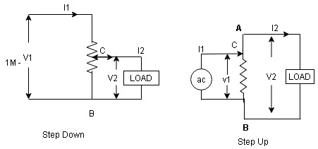
Fig A shows auto T/F as step down T/F variable terminal B C is connected to load and it acts as secondary wdg.
The position of point C is called as topping point can be selected as per requirement
Fig. B show auto T/F as step up T/F variable terminal B C is connected to supply side i.e. ac side and it acts as secondary winding
The operating principle of auto Transformer is same as that of 2 winding Transformer
Advantages
- Weight of copper required in an auto Transformer is always loss than that of the conventional 2 winding Transformer and hence it is chapter.
- Compact in size and loss costly.
- Losses taking place in Transformer is reduced hence efficiency is higher than conventional Transformer.
- Due to reduced resistance, voltage, regulation is better than conventional T/F.
Disadvantages:
As low voltage and high voltage sides are not separate then there is always risk of electric shocks when use for high vtg. Applications
Applications
- Starting squirrel cage induction motor and synchronous motor.
- Auto transformer as dimmer stat
- Used as variable ac to variable ac Voltage
5.Explain copper loss.
The Copper loss is due to resistance of the primary and secondary winding
It is load dependent / current dependent loss
As load on a transformer is variable (changing)  current changes
  copper loss is a variable loss
Primary secondary
Total C is loss = I12R12 + I22 R22
Copper loss depends upon load on T/F and is proportional to square of load current or KVA rating of transformer
 PCU
PCU  2
2 (KVA)2
F.L = full load
 PCU (at half load) =
  2 PCu F.L
= (0.5)2 PCU F.L.
Or PCu ( load) = (
 )2 PCu F.L