Question Bank
Module 1
DC circuits
- Explain the electrical circuits?
The three circuit elements are:
- Resistance R
- Capacitance C
- Inductance L
Resistance
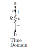
In time domain
v(t) = R . i(t)
i(t) = v(t) /R
Resistance is the static element where v(t) versus i(t) relationship is instantaneous.
Capacitance

Time domain
q(t) = C v(t)
i(t) = dq/dt = C dv/dt
Dv/dt = 1/C i(t)
 = v(t) – vo(t) = 1/C
  ) d
) d 
v(t) = v(to) + 1/C  ) d
) d 
Unlike the resistance for capacitance v(t) versus i(t) relationship at any time t depends on the past as they involve differentials and integrals. This implies that the capacitance is dynamic element. Capacitance stores energy.
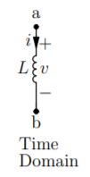
Inductance:
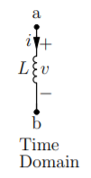
Time domain v(t) = L. Di/dt
Di/dt = 1/L v(t)
 = i(t) – i(to) = 1/L
  ) d
) d
i(t) = i(to) + 1/L  ) d
) d
2. Explain voltage source?
A voltage source is two-terminal device whose voltage at any instant of time is constant and is independent of the current drawn from it. Such a voltage source is called Ideal Voltage Source and has zero internal resistance.
Practically an ideal voltage source cannot be obtained.
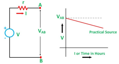
Sources having some amount of internal resistances are known as Practical Voltage Sourcebecause of theinternal resistance the voltage drop takes place which causes the terminal voltage to reduce. The smaller the internal resistance (r) of a voltage source the closer is the Ideal Source.
The symbolic representation of the ideal and practical voltage source is shown below.

Figure A shown below shows the circuit diagram and characteristics of an ideal voltage source:
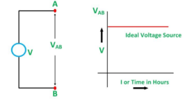
Figure A
Figure B shown below gives the circuit diagram and characteristics of Practical Voltage Source:
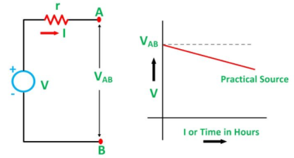
The example of voltage sources is batteries and alternators.
3. Explain current source?
The current sources isfurther categorised as Ideal and Practical current source.
An ideal current source is a two-terminal circuit element which supplies the same current to any load resistance connected across its terminals. The current supplied by the current source is independent of the voltage of source terminals. It has infinite resistance.
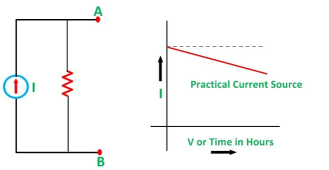
A practical current source is represented as an ideal current source connected with the resistance in parallel. The symbolic representation is shown below:

Figure C shown below shows the characteristics.
Figure D shown below shows the characteristics of Practical Current Source.
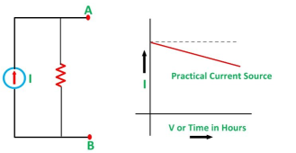
The example of current sources is photoelectric cells, collector currents of transistors.
4. Explain Kirchhoff’s Voltage Law?
Kirchhoff Voltage Law:
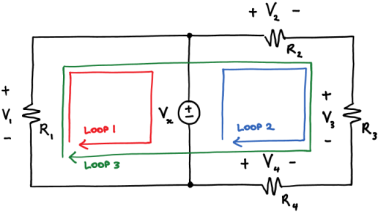
A loop is a path around a circuit that starts and ends in the same place.

Kirchhoff's voltage law (KVL) states that around a loop:
Sum of voltage rises=sum of voltage drops--------------------(1)
Applying KVL around the three loops we get
V1 = Vx KVL around loop 1
Vx + V4 = V2 + V3 KVL around loop2
V1 + V4 = V2 + V3 KVL around loop3
5. Explain Kirchhoff’s current law?
Kirchhoff Current Law:
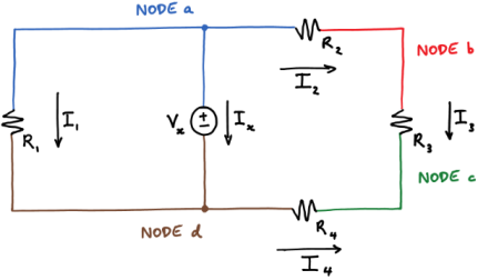
A node is a circuit connection that extends to all its neighbouring elements but does not contain them.
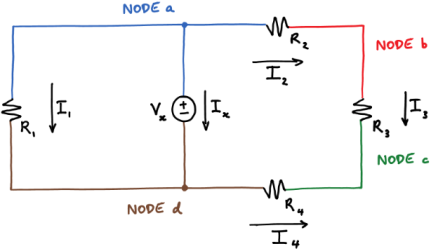
Kirchhoff’s current law states that at a node:
Sum of the in currents = sum of out currents
Applying KCL at four nodes
0 = Ix + I1 + I2 KCL at node a
I2 = I3 KCL at node b
I3 + I4 = 0 KCL at node c
Ix + I1 = I4 KCL at node d
Adding equations 6-9 gives the following equation:
Ix + I1 + I2 + I3 + I4 = Ix + I1 + I2 + I3 + I4.
6. Find the current and voltage using KVL?
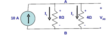
Using KVL we get
- I1 . 8 Ω + I2 . 4 Ω =0
Solving we get
I2 = 2 I1
Using KCL we get
I1 + I2 = 10
I1 + 2I1 = 10
3I1 = 10
I1 = 3.33 A
I2 = 6.67 A
VAB = 26.33 volts
7. Explain the analysis of simple circuits with dc excitation?
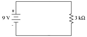
Consider a simple circuit with DC excitation:
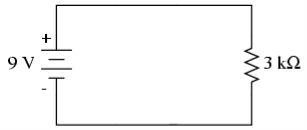
Analysis means to determine the voltages at all the nodes and currents in all the branches of the circuit.
A node is defined as a point where two or more components meet.
A branch is defined as any path between two nodes.
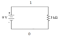
Here the nodes are 1 and 0
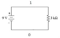
We have only two nodes here, ‘1’ and ‘0’.
‘0’ is the ground node. The ground node is at 0 volt.
Node ‘1’ is connected to the top of DC voltage source. So, it is 9 volts.
There are two branches in our circuit. One branch contains the 9V DC source and the other branch contains the 3k resistor.
From Ohm’s law we can calculate the current in the resistor.
I = V/R
This gives us a current of 9/3k = 3 mA.
The current in the resistor branch is 3 mA. And, because our circuit is one single closed loop, this current also flows in the other branch.
At this point, we know all the voltages at each node and the currents through each branch of our simple circuit.Hence, the analysis of our simple DC excitation circuit is complete.
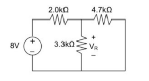
8.Using Superposition theorem determine the voltage drop and current across the resistor 3.3K as shown in figure below

Step 1:
Remove 8V power supply from the original circuit such that the new circuit becomes as the following and measure the voltage across resistor.

Here 3.3 K and 2K are in parallel therefore the resultant resistance will be 1.245K
Using voltage divider rule across 1.245K will be
V1 =[1.245/(1.245+4.7)] * 5 = 1.047V
Step 2:
Remove the 5V power supply from the original circuit such that the new circuit becomes the following and then measure the voltage across resistor.

Here 3.3K and 4.7K are in parallel therefore the resultant resistance will be 1.938K. Using voltage divider rule voltage across 1.938K will be
V2 =[1.938(1.938+2)] *8 = 3.9377V
Therefore, voltage drop across 3.3K resistor is V1+V2 = 1.047 + 3.9377 = 4.9847V
9.For the circuit shown in figure, find the current IL through 6 Ω resistor using Thevenin’s theorem.

Step-1:
Disconnect 6 Ω from the terminals ‘a’ and ‘b’ and the corresponding circuit diagram. Consider point ‘g’ as ground potential and other voltages are measured with respect to this point.
Step-2:
Apply any suitable method to find the Thevenin’s voltage (VTh )
KVL is applied around the closed path ‘gcag’ to compute Thevenin’s voltage.
42 – 8I – 4I -30 = 0 ; I = 1A
Vag = 30+4 = 34 volt
Vbg = 2 x 3 = 6 volt
Vth = Vab = Vag – Vbg = 34 -6 = 28 volt
Step-3:
Thevenin’s resistance RTh can be found by replacing all sources by their internal resistances all voltage sources are short-circuited and current sources are just removed or open circuited.
Rth = (8 x4) / 12 + 2 = 14/3 = 4.666Ω
Step-4:
Thevenin’s equivalent circuit is now equivalently represents the original circuit

IL = Vth / Rth + RL = 28 / 4.666 +6 = 2.625 A
10. Find RN, IN, the current flowing through and load Voltage across the load resistor in fig (1) by using Norton’s Theorem.

Step 1:
Short the 1.5 Ω load resistor.
Step 2:
Norton current.
Short AB terminals to obtain IN .The total resistance of the circuit is
2Ω + (6Ω || 3Ω)
RT = 4 Ω
IT = V / RT = 12/ 4 = 3 A
IN = 3 A x [ 6Ω / 3 + 6 )] = 2A
IN = 2A
Step 3:
Open current sources, Short Voltage sources and Open Load resistor.
Step 4:
Calculate Norton Resistance (RN)
Reduce 12V dc source. 3Ω resistor is in series with combination of 6Ω and 2Ω resistor
3Ω + (6Ω||2Ω)
3Ω + 1.5 Ω = 4.5 Ω; RN = 4.5 Ω
Step 5:
Connect RN in parallel with current source IN and the load resistor.
Step 6:
The load current through Load resistor
IL = IN x [ RN/(RN + RL)
=2 A x ( 4.5 / 4.5 + 1.5 K) = 1.5 A
IL = 1.5 A
The voltage across load resistor
VL = IL x RL
= 1.5 x 1.5
VL = 2.25 V
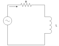
11. Explain Time domain analysis of first order RL circuits?
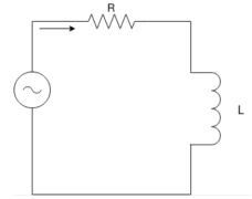
When switch ‘S’ is close at t>0 the as per KVL network equation will be …
R i(t) + L di(t)/dt = Vs ------------------------------------(1)
Above equation is non homogeneous equation linear differential equation of first oder. The solution of equation 1 will give i(t) which consists of two components :
Complimentary function
Which will satisfy di(t)/dt + R/L i(t) =0
Particular integral (if(t)) which will satisfy
R i(t) + L di(t)/dt = Vs
Thus the complete solution wil be
i(t) = in(t) + iJ(t)---------------------------------------(2)
i(t) = Io e –(R/L)t = Io e –(t/ -------------------------------------(3)
Where  time constant of RL circuit.
Equation (3) provides the natural response where
in(t) = K e –(R/L) t = K e –(t/τ) ----------------------------------(4)
Eq (1) can be written with i(t) = I constnt
RI + L dI/dt = Vs -------------------------------------------(5)
Since I= constsnt
L dI/dt =0
If(t) = I = Vs/R --------------------------------------------(6)
Substitute eq.4 and eq.6 yeilds the solution of eq(1)
i(t) = K e -t/ + Vs/R = K e-t/τ-------------------------------------------(7)
K is determined from initial condition that is t=0 and eq(7) will be
K = -Vs/R = -I ----------------------------------------------------(8)
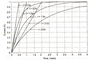
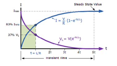
i(t) = Vs/R (1 – e –(R/L) t)
i(t) = I(1 – e -t/τ) for t>0
12. Explain the time domain analysis of RC circuit?
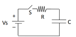
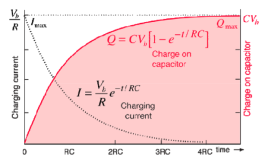
Fig. Shows a series RC circuit connected across a DC source through a switch S.
It is assumed that capacitor voltage id V0 When switch ‘S’ is close at t>0 the as per KVL network
Equation will be …
Vs – R i(t) – vc(t) =0 ------------------------------------------------(9)
For analysis of circuit of the figure the capacitor voltage Vc(t) is chosen as variable .
Substituting i(t) = c dvc(t)/dt in eq(9) we get
Eq(10) is like eq(1) it is also non homogeneous equation linear differential equation
Of first order .
Therefore the solution is similar to eq(1)
Vc(t) = k e -t/τ + Vs ---------------------------------------------(11)
In eq.(11) the time constant is τ = RC
By substituting value of K in eq(11) and after simplification we get --------
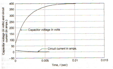
Vc(t) = Vo e (-t/τ) + Vs ( 1 – e -t/τ) V for t>0------------------------------------------(12)
The expression for the current in the circuit is given by ---------
i(t) = C dvc(t)/ dt
i(t) = C [ (-1/τ Vo e -t/τ ) + ((-1/τ Vs e -1/τ )]
i(t) = C/RC (Vs – Vo) e -t/τ

Question Bank
Module 1
Question Bank
Module 1
DC circuits
- Explain the electrical circuits?
The three circuit elements are:
- Resistance R
- Capacitance C
- Inductance L
Resistance
In time domain
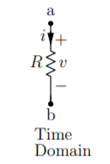
v(t) = R . i(t)
i(t) = v(t) /R
Resistance is the static element where v(t) versus i(t) relationship is instantaneous.
Capacitance

Time domain
q(t) = C v(t)
i(t) = dq/dt = C dv/dt
Dv/dt = 1/C i(t)
 = v(t) – vo(t) = 1/C
  ) d
) d 
v(t) = v(to) + 1/C  ) d
) d 
Unlike the resistance for capacitance v(t) versus i(t) relationship at any time t depends on the past as they involve differentials and integrals. This implies that the capacitance is dynamic element. Capacitance stores energy.
Inductance:
Time domain v(t) = L. Di/dt
Di/dt = 1/L v(t)
 = i(t) – i(to) = 1/L
  ) d
) d
i(t) = i(to) + 1/L  ) d
) d
2. Explain voltage source?
A voltage source is two-terminal device whose voltage at any instant of time is constant and is independent of the current drawn from it. Such a voltage source is called Ideal Voltage Source and has zero internal resistance.
Practically an ideal voltage source cannot be obtained.
Sources having some amount of internal resistances are known as Practical Voltage Sourcebecause of theinternal resistance the voltage drop takes place which causes the terminal voltage to reduce. The smaller the internal resistance (r) of a voltage source the closer is the Ideal Source.
The symbolic representation of the ideal and practical voltage source is shown below.
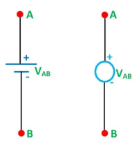
Figure A shown below shows the circuit diagram and characteristics of an ideal voltage source:
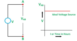
Figure A
Figure B shown below gives the circuit diagram and characteristics of Practical Voltage Source:
The example of voltage sources is batteries and alternators.
3. Explain current source?
The current sources isfurther categorised as Ideal and Practical current source.
An ideal current source is a two-terminal circuit element which supplies the same current to any load resistance connected across its terminals. The current supplied by the current source is independent of the voltage of source terminals. It has infinite resistance.
A practical current source is represented as an ideal current source connected with the resistance in parallel. The symbolic representation is shown below:
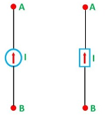
Figure C shown below shows the characteristics.
Figure D shown below shows the characteristics of Practical Current Source.
The example of current sources is photoelectric cells, collector currents of transistors.
4. Explain Kirchhoff’s Voltage Law?
Kirchhoff Voltage Law:
A loop is a path around a circuit that starts and ends in the same place.
Kirchhoff's voltage law (KVL) states that around a loop:
Sum of voltage rises=sum of voltage drops--------------------(1)
Applying KVL around the three loops we get
V1 = Vx KVL around loop 1
Vx + V4 = V2 + V3 KVL around loop2
V1 + V4 = V2 + V3 KVL around loop3
5. Explain Kirchhoff’s current law?
Kirchhoff Current Law:
A node is a circuit connection that extends to all its neighbouring elements but does not contain them.
Kirchhoff’s current law states that at a node:
Sum of the in currents = sum of out currents
Applying KCL at four nodes
0 = Ix + I1 + I2 KCL at node a
I2 = I3 KCL at node b
I3 + I4 = 0 KCL at node c
Ix + I1 = I4 KCL at node d
Adding equations 6-9 gives the following equation:
Ix + I1 + I2 + I3 + I4 = Ix + I1 + I2 + I3 + I4.
6. Find the current and voltage using KVL?

Using KVL we get
- I1 . 8 Ω + I2 . 4 Ω =0
Solving we get
I2 = 2 I1
Using KCL we get
I1 + I2 = 10
I1 + 2I1 = 10
3I1 = 10
I1 = 3.33 A
I2 = 6.67 A
VAB = 26.33 volts
7. Explain the analysis of simple circuits with dc excitation?
Consider a simple circuit with DC excitation:
Analysis means to determine the voltages at all the nodes and currents in all the branches of the circuit.
A node is defined as a point where two or more components meet.
A branch is defined as any path between two nodes.
Here the nodes are 1 and 0
We have only two nodes here, ‘1’ and ‘0’.
‘0’ is the ground node. The ground node is at 0 volt.
Node ‘1’ is connected to the top of DC voltage source. So, it is 9 volts.
There are two branches in our circuit. One branch contains the 9V DC source and the other branch contains the 3k resistor.
From Ohm’s law we can calculate the current in the resistor.
I = V/R
This gives us a current of 9/3k = 3 mA.
The current in the resistor branch is 3 mA. And, because our circuit is one single closed loop, this current also flows in the other branch.
At this point, we know all the voltages at each node and the currents through each branch of our simple circuit.Hence, the analysis of our simple DC excitation circuit is complete.
8.Using Superposition theorem determine the voltage drop and current across the resistor 3.3K as shown in figure below

Step 1:
Remove 8V power supply from the original circuit such that the new circuit becomes as the following and measure the voltage across resistor.

Here 3.3 K and 2K are in parallel therefore the resultant resistance will be 1.245K
Using voltage divider rule across 1.245K will be
V1 =[1.245/(1.245+4.7)] * 5 = 1.047V
Step 2:
Remove the 5V power supply from the original circuit such that the new circuit becomes the following and then measure the voltage across resistor.
Here 3.3K and 4.7K are in parallel therefore the resultant resistance will be 1.938K. Using voltage divider rule voltage across 1.938K will be
V2 =[1.938(1.938+2)] *8 = 3.9377V
Therefore, voltage drop across 3.3K resistor is V1+V2 = 1.047 + 3.9377 = 4.9847V
9.For the circuit shown in figure, find the current IL through 6 Ω resistor using Thevenin’s theorem.

Step-1:
Disconnect 6 Ω from the terminals ‘a’ and ‘b’ and the corresponding circuit diagram. Consider point ‘g’ as ground potential and other voltages are measured with respect to this point.
Step-2:
Apply any suitable method to find the Thevenin’s voltage (VTh )
KVL is applied around the closed path ‘gcag’ to compute Thevenin’s voltage.
42 – 8I – 4I -30 = 0 ; I = 1A
Vag = 30+4 = 34 volt
Vbg = 2 x 3 = 6 volt
Vth = Vab = Vag – Vbg = 34 -6 = 28 volt
Step-3:
Thevenin’s resistance RTh can be found by replacing all sources by their internal resistances all voltage sources are short-circuited and current sources are just removed or open circuited.
Rth = (8 x4) / 12 + 2 = 14/3 = 4.666Ω
Step-4:
Thevenin’s equivalent circuit is now equivalently represents the original circuit

IL = Vth / Rth + RL = 28 / 4.666 +6 = 2.625 A
10. Find RN, IN, the current flowing through and load Voltage across the load resistor in fig (1) by using Norton’s Theorem.

Step 1:
Short the 1.5 Ω load resistor.
Step 2:
Norton current.
Short AB terminals to obtain IN .The total resistance of the circuit is
2Ω + (6Ω || 3Ω)
RT = 4 Ω
IT = V / RT = 12/ 4 = 3 A
IN = 3 A x [ 6Ω / 3 + 6 )] = 2A
IN = 2A
Step 3:
Open current sources, Short Voltage sources and Open Load resistor.
Step 4:
Calculate Norton Resistance (RN)
Reduce 12V dc source. 3Ω resistor is in series with combination of 6Ω and 2Ω resistor
3Ω + (6Ω||2Ω)
3Ω + 1.5 Ω = 4.5 Ω; RN = 4.5 Ω
Step 5:
Connect RN in parallel with current source IN and the load resistor.
Step 6:
The load current through Load resistor
IL = IN x [ RN/(RN + RL)
=2 A x ( 4.5 / 4.5 + 1.5 K) = 1.5 A
IL = 1.5 A
The voltage across load resistor
VL = IL x RL
= 1.5 x 1.5
VL = 2.25 V
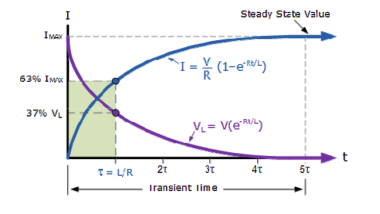
11. Explain Time domain analysis of first order RL circuits?
When switch ‘S’ is close at t>0 the as per KVL network equation will be …
R i(t) + L di(t)/dt = Vs ------------------------------------(1)
Above equation is non homogeneous equation linear differential equation of first oder. The solution of equation 1 will give i(t) which consists of two components :
Complimentary function
Which will satisfy di(t)/dt + R/L i(t) =0
Particular integral (if(t)) which will satisfy
R i(t) + L di(t)/dt = Vs
Thus the complete solution wil be
i(t) = in(t) + iJ(t)---------------------------------------(2)
i(t) = Io e –(R/L)t = Io e –(t/ -------------------------------------(3)
Where  time constant of RL circuit.
Equation (3) provides the natural response where
in(t) = K e –(R/L) t = K e –(t/τ) ----------------------------------(4)
Eq (1) can be written with i(t) = I constnt
RI + L dI/dt = Vs -------------------------------------------(5)
Since I= constsnt
L dI/dt =0
If(t) = I = Vs/R --------------------------------------------(6)
Substitute eq.4 and eq.6 yeilds the solution of eq(1)
i(t) = K e -t/ + Vs/R = K e-t/τ-------------------------------------------(7)
K is determined from initial condition that is t=0 and eq(7) will be
K = -Vs/R = -I ----------------------------------------------------(8)
i(t) = Vs/R (1 – e –(R/L) t)
i(t) = I(1 – e -t/τ) for t>0

12. Explain the time domain analysis of RC circuit?
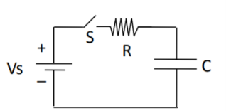
Fig. Shows a series RC circuit connected across a DC source through a switch S.
It is assumed that capacitor voltage id V0 When switch ‘S’ is close at t>0 the as per KVL network
Equation will be …
Vs – R i(t) – vc(t) =0 ------------------------------------------------(9)
For analysis of circuit of the figure the capacitor voltage Vc(t) is chosen as variable .
Substituting i(t) = c dvc(t)/dt in eq(9) we get
Eq(10) is like eq(1) it is also non homogeneous equation linear differential equation
Of first order .
Therefore the solution is similar to eq(1)
Vc(t) = k e -t/τ + Vs ---------------------------------------------(11)
In eq.(11) the time constant is τ = RC
By substituting value of K in eq(11) and after simplification we get --------
Vc(t) = Vo e (-t/τ) + Vs ( 1 – e -t/τ) V for t>0------------------------------------------(12)
The expression for the current in the circuit is given by ---------
i(t) = C dvc(t)/ dt
i(t) = C [ (-1/τ Vo e -t/τ ) + ((-1/τ Vs e -1/τ )]
i(t) = C/RC (Vs – Vo) e -t/τ

