ENGINEERING GRAPHICS AND DESIGN
UNIT 9
Demonstration of a simple team design project that illustrates
QUESTION BANK
Q.1 Explain Geometry and topology of engineered components: ?
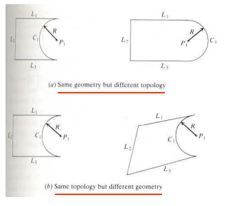
Complete part representation including topological and geometrical data
– Geometry: shape and dimensions
– Topology: the connectivity and associatively of the object entities; it determines the relational information between object entities
• Able to transfer data directly from CAD to CAE and CAM.
• Support various engineering applications, such as mass properties, mechanism analysis, FEA/FEM and tool path creation for CNC, and so on.
Geometric modeling is only Geometric modeling is only a means a means not the goal the goal in engineering.
• Engineering analysis needs product geometry; the degree of detail depends on the analysis procedure that utilizes the geometry.
• There is no model that is sufficient to study all behavioral aspects of an engineering component or a behavioral aspects of an engineering component or system.
• Attributes facilitate analysis and grow with applications

Q.2 What is Meshed topologies for engineering ?
Mesh systems usually rely on a routing table, which tells every node
(a) how to communicate with the access point, and
(b) how a node should direct traffic that is trying to go somewhere. The routing table assumes that there is not direct communication anywhere in the network except by nodes that have a route to the access point. It’s like a big game of telephone—if you don’t know the route, then you send the message to someone that has the route established. Routing tables are comprised of:
- Source identifier
- Destination identifier
- Source sequence number
- Destination sequence number
- Broadcast identifier
- Time to live
Q.3 Explain tool-path generation strategy?
- Tool Path Distribution Strategy
There are several strategies of distributing the tool path in the domain of the designed part. The goal of tool path distribution strategies is to span the entire designed part. The commonly used tool path distribution strategies are
1. Zig-zag or raster curves
2. Contour curves
3. Spiral curves
4. Space filling curves
5. Sequential generated curves In this section, we outline commonly used tool path distribution strategies.
- Zig-zag Curves: The most commonly used tool path distribution strategies is the zig-zag strategy, due to the simple algorithm involved in calculating the spanning elements. This strategy involves filling the domain with parallel rays which are trimmed at the boundaries.
2. Contour Curves: The contour strategy is advantageous when the boundary contours are included as spanning elements, since a uniform boundary results. This strategy involves shrinking/expanding contours till the entire domain is spanned.
3. Space Filling Curves: The previous strategies give a directionality or lay to the surface finish on the manufactured part. The space filling strategy avoids the directionality by frequent changes in orientation of the spanning elements by means of recursive algorithms. The disadvantage of using the space filling strategy is that the overall length of the spanning elements, in general, is large, increasing manufacturing time. In addition, the number of short spanning elements is disadvantageous to the NC machine, since the tool is unable to accelerate to the specified feedrate.
4. Sequential Curves: This strategies involves sequentially generating spanning elements starting with a given initial spanning element. The sequential distribution strategy is advantageous due to the flexibility of generating various geometries of spanning elements. The disadvantage of this strategy is the complexity involved in calculating spanning elements.
Q.4 Explain Geometric dimensioning and tolerancing?
Dimensioning guidelines, tolerancing techniques
Geometric Dimensioning and Tolerancing (GD&T) is a system for defining and communicating engineering tolerances. It uses a symbolic language on engineering drawings and computer-generated three-dimensional solid models that explicitly describe nominal geometry and its allowable variation. It tells the manufacturing staff and machines what degree of accuracy and precision is needed on each controlled feature of the part. GD&T is used to define the nominal (theoretically perfect) geometry of parts and assemblies, to define the allowable variation in form and possible size of individual features, and to define the allowable variation between features.
Dimensioning specifications define the nominal, as-modeled or as-intended geometry. One example is a basic dimension.
Tolerancing specifications define the allowable variation for the form and possibly the size of individual features, and the allowable variation in orientation and location between features. Two examples are linear dimensions and feature control frames using a datum reference (both shown above).
Q.5 Explain about Use of solid-modeling software for creating associative models at the component and assembly levels?
Assembly modeling is a technology and method used by computer-aided design and product visualization computer software systems to handle multiple files that represent components within a product. The components within an assembly are represented as solid or surface models.
The designer generally has access to models that others are working on concurrently. For example, several people may be designing one machine that has many parts. New parts are added to an assembly model as they are created. Each designer has access to the assembly model, while a work in progress, and while working in their own parts. The design evolution is visible to everyone involved. Depending on the system, it might be necessary for the users to acquire the latest versions saved of each individual components to update the assembly.
The individual data files describing the 3D geometry of individual components are assembled together through a number of sub-assembly levels to create an assembly describing the whole product. All CAD and CPD systems support this form of bottom-up construction. Some systems, via associative copying of geometry between components also allow top-down method of design.
Components can be positioned within the product assembly using absolute coordinate placement methods or by means of mating conditions. Mating conditions are definitions of the relative position of components between each other; for example alignment of axis of two holes or distance of two faces from one another. The final position of all components based on these relationships is calculated using a geometry constraint engine built into the CAD or visualization package.
The importance of assembly modeling in achieving the full benefits of PLM has led to ongoing advances in this technology. These include the use of lightweight data structures such as JT that allow visualization of and interaction with large amounts of product data, direct interface to between Digital Mock ups and PDM systems and active digital mock up technology that unites the ability to visualize the assembly mock up with the ability to measure, analyze, simulate, design and redesign.
Solid modeling (or modelling) is a consistent set of principles for mathematical and computer modeling of three-dimensional solids. Solid modeling is distinguished from related areas of geometric modeling and computer graphics by its emphasis on physical fidelity.[1] Together, the principles of geometric and solid modeling form the foundation of 3D-computer-aided design and in general support the creation, exchange, visualization, animation, interrogation, and annotation of digital models of physical objects.
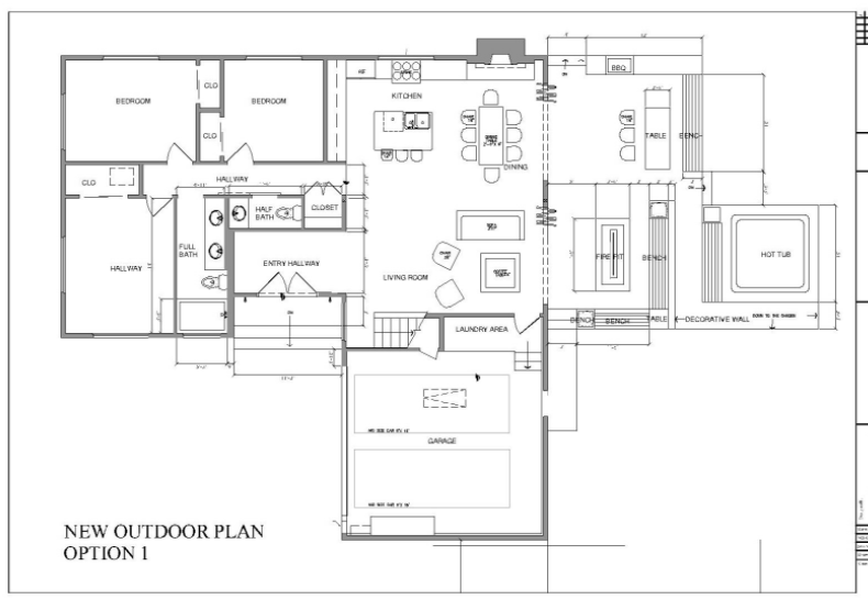
Q.6 Draw rough plain showing Floor plans that include: windows, doors, and fixtures such as WC, bath, sink, shower, etc. ?

Q.7 Explain about Applying colour coding according to building drawing practice?
Assigning colors to layers is very important and should be done as you create them or soon after. The reasons to have color are twofold. On the most basic level, a colorful drawing is more pleasant to look at on the screen, but more important, it is easier to interpret and work with. If, for example, your walls are green and you keep this in mind, then your eye is able to quickly see and assess the design. Likewise, yellow doors are easy to spot. This color separation greatly aids in drafting. Imagine a scenario where your building floor plan is made up of all white lines; you would be unable to tell one line from another. As that drawing grew more complex, all the lines would melt into one monochrome mess. Finally, colors are assigned pen thicknesses (an advanced topic) and contribute to more professional-looking output. We address this in Level 2.
To assign colors, let us turn our attention back to the Layers dialog box. Highlight, by clicking once, layer A-Walls. Now, follow the blue ribbon across until you see a box with the word white next to it. It will be under the Color column. Click on it, and the Select Color dialog box appears
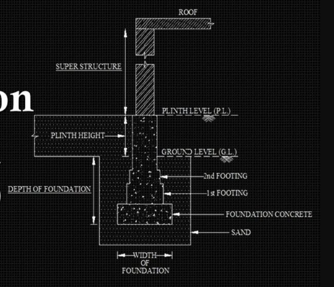
7. Draw a sectional elevation showing foundation to ceiling?

8. Explain Building Information Modelling (BIM)?
Building Information Modeling (BIM) is the process of creating and managing 3D building data during its development. BIM is a complex multiphase process that gathers input from team members to model the components and tools that will be used during the construction process to create a unique perspective of the building process.
The 3D process is aimed at achieving savings through collaboration and visualization of building components into an early design process that will dictate changes and modifications to the actual construction process. It is a very powerful tool that when used properly will save money, time and simplify the construction process.
9. What are the applications of Building Information Modeling?
The BIM application process can be used during design and architecture process creating a clear picture used for better and more integrated designs. The software will be used to foresee problems and coordination between different contractors and as a way to generate construction documents and process that will later be implemented during the physical process. It is ideal when there are many trades executing at the same moment or when schedules are compressed. There are multiple applications for BIM so it can be used by the following groups:
- Architecture
- Sustainability
- Structures
- MEP
- Construction management
- Utilities
- Road construction
- Scheduling
- Property management
10. What are the BENEFITS OF BIM
Benefits of working in a BIM environment are evident across the project life cycle from design through maintenance.
The clarity gained through enhanced communication of well-organized project information with the help of BIM models shows an over-all increase in productivity and project quality.
Building Information Modeling has proven record of increase in productivity and the quality of the project. BIM enables better design decisions by allowing the project teams to develop and experience the building virtually before the construction. Communicating the project information visually using 3D environment highly reduces the loss of information.