UNIT 3
Projections of Regular Solids
1. Draw the projections of a triangular prism, base 40 mm side and axis 50 mm long, resting on one of its bases on the H.P. With a vertical face perpendicular to the V.P.

(i) As the axis is perpendicular to the ground i.e. the H.P. Begin with the top view. It will be an equilateral triangle of sides 40 mm long, with one of its sides perpendicular to xy. Name the corners as shown, thus completing the top view. The corners d, e and fare hidden and coincide with the top corners a, b and c respectively
(ii) Project the front view, which will be a rectangle. Name the corners. The line b'e' coincides with a'd'.
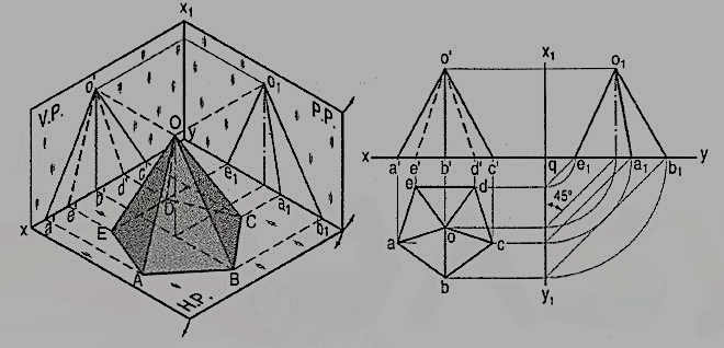
2. Draw the projections of a pentagonal pyramid, base 30 mm edge and axis 50 mm long, having its base on the H.P. And an edge of the base parallel to the V.P. Also draw its side view.

(i) Assume the side DE which is nearer the V.P., to be parallel to the V.P. As shown in the pictorial view.
(ii) In the top view, draw a regular pentagon abcde with ed parallel to and nearer xy. Locate its centre o and join it with the corners to indicate the slant edges.
(iii) Through o, project the axis in the front view and mark the apex o', 50 mm above xy. Project all the corners of the base on xy. Draw lines o'a', o'b' and o'c' to show the visible edges. Show o'd' and o'e' for the hidden edges as dashed lines.
(iv) For the side view looking from the left, draw a new reference line x1y1 perpendicular to xy and to the right of the front view. Project the side view on it, horizontally from the front view as shown. The respective distances of all the points in the side view from x1y1, should be equal to their distances in the top view from xy. This is done systematically as explained below:
(v) From each point in the top view, draw horizontal lines up to x1y1. Then draw lines inclined at 45° to x1y1 (or xy) as shown. Or, with q, the point of intersection between xy and x1y1 as centre, draw quarter circles. Project up all the points to intersect the corresponding horizontal lines from the front view and complete the side view as shown in the figure. Lines o1d1 and o1c1 coincide with o1e1 and o1a1 respectively.
3. A hexagonal prism (fig. 14) has one of its rectangular faces parallel to the H.P. Its axis is perpendicular to the V.P. And 3.5 cm above the ground. Draw its projections when the nearer end is 2 cm in front of the V.P. Side of base 2.5 cm long; axis 5 cm long.

(i) Begin with the front view. Construct a regular hexagon of 2.5 cm long sides with its centre 3.5 cm above xy and one side parallel to it.
(ii) Project down the top view, keeping the line for nearer end, viz. 1-4, 2 cm below xy.
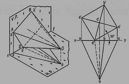
4. A square pyramid fig. 15, base 40 mm side and axis 65 mm long, has its base in the V.P. One edge of the base is inclined at 30° to the H.P. And a corner contained by that edge is on the H.P. Draw its projections.
(i) Draw a square in the front view with the corner d' in xy and the side d'c' inclined at 30° to it. Locate the centre o' and join it with the corners of the square.
(ii) Project down all the corners in xy (because the base is in the V.P.). Mark the apex o on a projector through o'. Draw lines for the slant edges and complete the top view.
Figure
5. A triangular prism1 base 40 mm side and height 65 mm is resting on the H.P. On one of its rectangular faces with the axis parallel to the V.P. Draw its projections.
As the axis is parallel to both the planes, begin with the side view.
(i) Draw an equilateral triangle representing the side view, with one side in xy.
(ii) Project the front view horizontally from this triangle.
(iii) Project down the top view from the front view and the side view, as shown.

6. Draw the projections of the following solids, situated in their respective positions, taking a side of the base 40 mm long or the diameter of the base 50 mm long and the axis 65 mm long.
1. A hexagonal pyramid, base on the H.P. And a side of the base parallel to and 25 mm in front of the V.P.
2. A square prism, base on the H.P., a side of the base inclined at 30° to the V.P. And the axis 50 mm in front of the V.P.
3. A triangular pyramid, base on the H.P. And an edge of the base inclined at 45° to the V.P.; the apex 40 mm in front of the V.P.
7. Draw the projections of a pentagonal prism, base 25 mm side and axis 50 mm long, resting on one of its faces on the H.P., with the axis inclined at 45° to the V.P.
In the simple position, assume the prism to be on one of its faces on the ground with the axis perpendicular to the V.P.
Draw the pentagon in the front view with one side in xy and project the top view [fig. 17].
The shape and size of the figure in the top view will not change, so long as the prism has its face on the H.P. The respective distances of all the corners in the front view from xy will also remain constant.
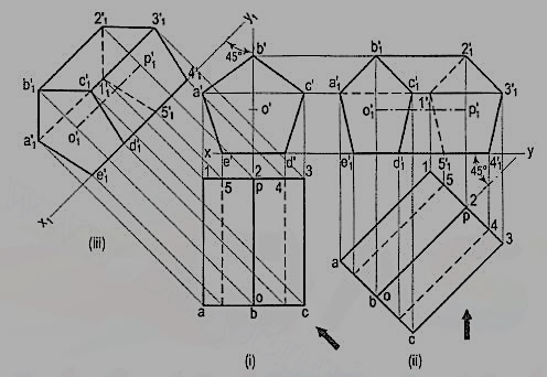
Method I: [fig. 17 (i)]:
(i) Alter the position of the top view, i.e. reproduce it so that the axis is inclined at 45° to xy. Project all the points upwards from this top view and horizontally from the first front view, e.g. a vertical from a intersecting a horizontal from a' at a point a'1.
(ii) Complete the pentagon a'1b'1c'1d'1e'1 for the fully visible end of the prism. Next, draw the lines for the longer edges and finally, draw the lines for the edges of the other end. Note carefully that the lines a'1 1'1, 1'12'1 and 1'15'1 are dashed lines. e'1 5'1 is also hidden but it coincides with other visible lines.
Method II: [fig. 17(ii)]:
(i) Draw a new reference line x1y1, making 45° angle with the top view of the axis, to represent an auxiliary vertical plane.
(ii) Draw projectors from all the points in the top view perpendicular to x1y1 and on them, mark points keeping the distance of each point from x1y1 equal to its distance from xy in the front view. Join the points as already explained. The auxiliary front view and the top view are the required projections.
8. A hexagonal pyramid, base 25 mm side and axis 50 mm long, has an edge of its base on the ground. Its axis is inclined at 30° to the ground and parallel to the V.P. Draw its projections. In the initial position assume the axis to be perpendicular to the H.P.
Draw the projections with the base in xy and its one edge perpendicular to the V.P. Fig. 18 (i)
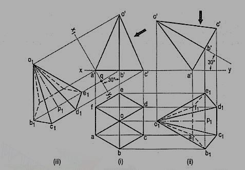
If the pyramid is now tilted about the edge AF (or CD) the axis will become inclined to the H.P. But will remain parallel to the V.P. The distances of all the corners from the V.P. Will remain constant.
The front view will not be affected except in its position in relation to xy. The new top view will have its corners at same distances from xy, as before.
Method I: [fig. 18 (ii)]:
(i) Reproduce the front view so that the axis makes 30° angle with xy and the point a' remains in xy.
(ii) Project all the points vertically from this front view and horizontally from the first top view. Complete the new top view by drawing (a) lines joining the apex o'1 with the corners of the base and (b) lines for the edges of the base.
The base will be partly hidden as shown by dashed line a1b1, e1f1 and f1a1. Similarly, o1f1 and o1a1 are also dashed lines.
Method II: [fig. 18(iii)]:
(i) Through a' draw a new reference line x1y1 inclined at 30° to the axis, to represent an auxiliary inclined plane.
(ii) From the front view project, the required top view on x1y1, keeping the distance of each point from x1y1 equal to the distance of its first top view from xy, viz. e1q = eb' etc.
9.Draw the projections of a cone, base 75 mm diameter and axis 100 mm long, lying on the H.P. On one of its generators with the axis parallel to the V.P.
(i) Assuming the cone to be resting on its base on the ground, draw its projections.
(ii) Re-draw the front view so that the line o'7' (or o'1 ') is in xy. Project the required top view as shown. The lines from o1 should be tangents to the ellipse.

The top view obtained by auxiliary-plane method is shown in fig. 13-24(ii). The new reference line x1y1 is so drawn as to contain the generator o'1' instead of o'7' (for sake of convenience). The cone is thus lying on the generator o'1 '. Note that 1 '1 1 = 1 '1, o'o1 = 4'o etc. Also note that the base is fully visible in both the methods.
10. A square prism, base 40 mm side and height 65 mm, has its axis inclined at 45° to the H.P. And has an edge of its base, on the H.P and inclined at 30° to the V.P. Draw its projections.
Method I: Fig. 20
i) Assuming the prism to be resting on its base on the ground with an edge of the base perpendicular to the V.P., draw its projections. Assume the prism to be tilted about the edge which is perpendicular to the V.P., so that the axis makes 45° angle with the H.P.
(ii) Hence, change the position of the front view so that the axis is inclined at 45° to xy and f' (or e') is in xy. Project the second top view. Again, assume the prism to be turned so that the edge on which it rests, makes an angle of 30° with the V.P., keeping the inclination of the axis with the ground constant. The shape and size of the second top view will remain the same; only its position will change. In the front view, the distances of all the corners from xy will remain the same as in the second front view.
(iii) Therefore, reproduce the second top view making f1g1 inclined at 30° to xy. Project the final front view upwards from this top view and horizontally from the second front view, e.g. a vertical from a1 and a horizontal from a' intersecting at a'1. As the top end is further away from xy in the top view it will be fully visible in the front view. Complete the front view showing the hidden edges by dashed lines.
(iv) The second top view may be turned in the opposite direction as shown. In this position, the lower end of the prism, viz. e'lf'1g'1h'1 will be fully visible in the front view.

Figure
Method II: Fig. 21
(i) Draw the top view and front view in simple position.
(ii) Through f', draw a new reference line x1y1 making 45° angle with the axis. On it, project the auxiliary top view.
(iii) Draw another reference line x2y2 inclined at 30° to the line fig 1. From the auxiliary top view, project the required front view, keeping the distance of each point from x2y2, equal to its distance (in the first front view) from x1y1 i.e. a'1q1 = a'q etc.
UNIT 3
Projections of Regular Solids
1. Draw the projections of a triangular prism, base 40 mm side and axis 50 mm long, resting on one of its bases on the H.P. With a vertical face perpendicular to the V.P.

(i) As the axis is perpendicular to the ground i.e. the H.P. Begin with the top view. It will be an equilateral triangle of sides 40 mm long, with one of its sides perpendicular to xy. Name the corners as shown, thus completing the top view. The corners d, e and fare hidden and coincide with the top corners a, b and c respectively
(ii) Project the front view, which will be a rectangle. Name the corners. The line b'e' coincides with a'd'.
2. Draw the projections of a pentagonal pyramid, base 30 mm edge and axis 50 mm long, having its base on the H.P. And an edge of the base parallel to the V.P. Also draw its side view.
(i) Assume the side DE which is nearer the V.P., to be parallel to the V.P. As shown in the pictorial view.
(ii) In the top view, draw a regular pentagon abcde with ed parallel to and nearer xy. Locate its centre o and join it with the corners to indicate the slant edges.
(iii) Through o, project the axis in the front view and mark the apex o', 50 mm above xy. Project all the corners of the base on xy. Draw lines o'a', o'b' and o'c' to show the visible edges. Show o'd' and o'e' for the hidden edges as dashed lines.
(iv) For the side view looking from the left, draw a new reference line x1y1 perpendicular to xy and to the right of the front view. Project the side view on it, horizontally from the front view as shown. The respective distances of all the points in the side view from x1y1, should be equal to their distances in the top view from xy. This is done systematically as explained below:
(v) From each point in the top view, draw horizontal lines up to x1y1. Then draw lines inclined at 45° to x1y1 (or xy) as shown. Or, with q, the point of intersection between xy and x1y1 as centre, draw quarter circles. Project up all the points to intersect the corresponding horizontal lines from the front view and complete the side view as shown in the figure. Lines o1d1 and o1c1 coincide with o1e1 and o1a1 respectively.
3. A hexagonal prism (fig. 14) has one of its rectangular faces parallel to the H.P. Its axis is perpendicular to the V.P. And 3.5 cm above the ground. Draw its projections when the nearer end is 2 cm in front of the V.P. Side of base 2.5 cm long; axis 5 cm long.

(i) Begin with the front view. Construct a regular hexagon of 2.5 cm long sides with its centre 3.5 cm above xy and one side parallel to it.
(ii) Project down the top view, keeping the line for nearer end, viz. 1-4, 2 cm below xy.
4. A square pyramid fig. 15, base 40 mm side and axis 65 mm long, has its base in the V.P. One edge of the base is inclined at 30° to the H.P. And a corner contained by that edge is on the H.P. Draw its projections.
(i) Draw a square in the front view with the corner d' in xy and the side d'c' inclined at 30° to it. Locate the centre o' and join it with the corners of the square.
(ii) Project down all the corners in xy (because the base is in the V.P.). Mark the apex o on a projector through o'. Draw lines for the slant edges and complete the top view.

Figure
5. A triangular prism1 base 40 mm side and height 65 mm is resting on the H.P. On one of its rectangular faces with the axis parallel to the V.P. Draw its projections.
As the axis is parallel to both the planes, begin with the side view.
(i) Draw an equilateral triangle representing the side view, with one side in xy.
(ii) Project the front view horizontally from this triangle.
(iii) Project down the top view from the front view and the side view, as shown.
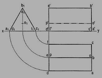
6. Draw the projections of the following solids, situated in their respective positions, taking a side of the base 40 mm long or the diameter of the base 50 mm long and the axis 65 mm long.
1. A hexagonal pyramid, base on the H.P. And a side of the base parallel to and 25 mm in front of the V.P.
2. A square prism, base on the H.P., a side of the base inclined at 30° to the V.P. And the axis 50 mm in front of the V.P.
3. A triangular pyramid, base on the H.P. And an edge of the base inclined at 45° to the V.P.; the apex 40 mm in front of the V.P.
7. Draw the projections of a pentagonal prism, base 25 mm side and axis 50 mm long, resting on one of its faces on the H.P., with the axis inclined at 45° to the V.P.
In the simple position, assume the prism to be on one of its faces on the ground with the axis perpendicular to the V.P.
Draw the pentagon in the front view with one side in xy and project the top view [fig. 17].
The shape and size of the figure in the top view will not change, so long as the prism has its face on the H.P. The respective distances of all the corners in the front view from xy will also remain constant.
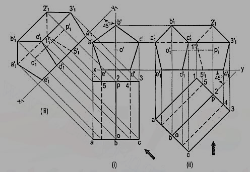
Method I: [fig. 17 (i)]:
(i) Alter the position of the top view, i.e. reproduce it so that the axis is inclined at 45° to xy. Project all the points upwards from this top view and horizontally from the first front view, e.g. a vertical from a intersecting a horizontal from a' at a point a'1.
(ii) Complete the pentagon a'1b'1c'1d'1e'1 for the fully visible end of the prism. Next, draw the lines for the longer edges and finally, draw the lines for the edges of the other end. Note carefully that the lines a'1 1'1, 1'12'1 and 1'15'1 are dashed lines. e'1 5'1 is also hidden but it coincides with other visible lines.
Method II: [fig. 17(ii)]:
(i) Draw a new reference line x1y1, making 45° angle with the top view of the axis, to represent an auxiliary vertical plane.
(ii) Draw projectors from all the points in the top view perpendicular to x1y1 and on them, mark points keeping the distance of each point from x1y1 equal to its distance from xy in the front view. Join the points as already explained. The auxiliary front view and the top view are the required projections.
8. A hexagonal pyramid, base 25 mm side and axis 50 mm long, has an edge of its base on the ground. Its axis is inclined at 30° to the ground and parallel to the V.P. Draw its projections. In the initial position assume the axis to be perpendicular to the H.P.
Draw the projections with the base in xy and its one edge perpendicular to the V.P. Fig. 18 (i)

If the pyramid is now tilted about the edge AF (or CD) the axis will become inclined to the H.P. But will remain parallel to the V.P. The distances of all the corners from the V.P. Will remain constant.
The front view will not be affected except in its position in relation to xy. The new top view will have its corners at same distances from xy, as before.
Method I: [fig. 18 (ii)]:
(i) Reproduce the front view so that the axis makes 30° angle with xy and the point a' remains in xy.
(ii) Project all the points vertically from this front view and horizontally from the first top view. Complete the new top view by drawing (a) lines joining the apex o'1 with the corners of the base and (b) lines for the edges of the base.
The base will be partly hidden as shown by dashed line a1b1, e1f1 and f1a1. Similarly, o1f1 and o1a1 are also dashed lines.
Method II: [fig. 18(iii)]:
(i) Through a' draw a new reference line x1y1 inclined at 30° to the axis, to represent an auxiliary inclined plane.
(ii) From the front view project, the required top view on x1y1, keeping the distance of each point from x1y1 equal to the distance of its first top view from xy, viz. e1q = eb' etc.
9.Draw the projections of a cone, base 75 mm diameter and axis 100 mm long, lying on the H.P. On one of its generators with the axis parallel to the V.P.
(i) Assuming the cone to be resting on its base on the ground, draw its projections.
(ii) Re-draw the front view so that the line o'7' (or o'1 ') is in xy. Project the required top view as shown. The lines from o1 should be tangents to the ellipse.

The top view obtained by auxiliary-plane method is shown in fig. 13-24(ii). The new reference line x1y1 is so drawn as to contain the generator o'1' instead of o'7' (for sake of convenience). The cone is thus lying on the generator o'1 '. Note that 1 '1 1 = 1 '1, o'o1 = 4'o etc. Also note that the base is fully visible in both the methods.
10. A square prism, base 40 mm side and height 65 mm, has its axis inclined at 45° to the H.P. And has an edge of its base, on the H.P and inclined at 30° to the V.P. Draw its projections.
Method I: Fig. 20
i) Assuming the prism to be resting on its base on the ground with an edge of the base perpendicular to the V.P., draw its projections. Assume the prism to be tilted about the edge which is perpendicular to the V.P., so that the axis makes 45° angle with the H.P.
(ii) Hence, change the position of the front view so that the axis is inclined at 45° to xy and f' (or e') is in xy. Project the second top view. Again, assume the prism to be turned so that the edge on which it rests, makes an angle of 30° with the V.P., keeping the inclination of the axis with the ground constant. The shape and size of the second top view will remain the same; only its position will change. In the front view, the distances of all the corners from xy will remain the same as in the second front view.
(iii) Therefore, reproduce the second top view making f1g1 inclined at 30° to xy. Project the final front view upwards from this top view and horizontally from the second front view, e.g. a vertical from a1 and a horizontal from a' intersecting at a'1. As the top end is further away from xy in the top view it will be fully visible in the front view. Complete the front view showing the hidden edges by dashed lines.
(iv) The second top view may be turned in the opposite direction as shown. In this position, the lower end of the prism, viz. e'lf'1g'1h'1 will be fully visible in the front view.

Figure
Method II: Fig. 21
(i) Draw the top view and front view in simple position.
(ii) Through f', draw a new reference line x1y1 making 45° angle with the axis. On it, project the auxiliary top view.
(iii) Draw another reference line x2y2 inclined at 30° to the line fig 1. From the auxiliary top view, project the required front view, keeping the distance of each point from x2y2, equal to its distance (in the first front view) from x1y1 i.e. a'1q1 = a'q etc.