UNIT 4
Development of Surfaces
- What do you understand by Development of surfaces, explain its importance?
“The development of surface of an object means the unrolling and unfolding of all surfaces of the object on a plane.” “If the surface of a solid is laid out on a plain surface, the shape thus obtained is called the development of that solid.” In other words, the development of a solid is the shape of a plain sheet that by proper folding could be converted into the shape of the concerned solid.
The knowledge of development of surfaces is essential in many industries such as automobile, aircraft, ship building, packaging and sheet-metal work. In construction of boilers, bins, process-vessels, hoppers, funnels, chimneys etc., the plates are marked and cut according to the developments which, when folded, form the desired objects. The form of the sheet obtained by laying all the outer surfaces of the solid with suitable allowances for the joints is known as pattern.
Importance of Development: Knowledge of development is very useful in sheet metal work, construction of storage vessels, chemical vessels, boilers, and chimneys. Such vessels are manufactured from plates that are cut according to these developments and then properly bend into desired shaped. The joints are then welded or riveted.
2. Briefly explain the principle methods of development of surfaces?
Principle of Development: Every line on the development should show the true length of the corresponding line on the surface which is developed.
Methods of Development:
(a) Parallel-line development
(b) Radial-line development
(c) Triangulation development
(d) Approximate development
Parallel-line Method: It is used for developing prisms and single curved surfaces like cylinders, in which all the edges/generation of lateral surfaces are parallel in each other.
Radial-line Method: It is employed for pyramids and single curved surfaces like cones in which the apex is taken as centre and the slant edge or generator as radius of its development.
Triangulation Method: It is used for developing transition pieces.
Approximate Method: It is employed for double curved surfaces like spheres, as they are theoretically not possible to develop. The surface of the sphere is developed by approximate method.
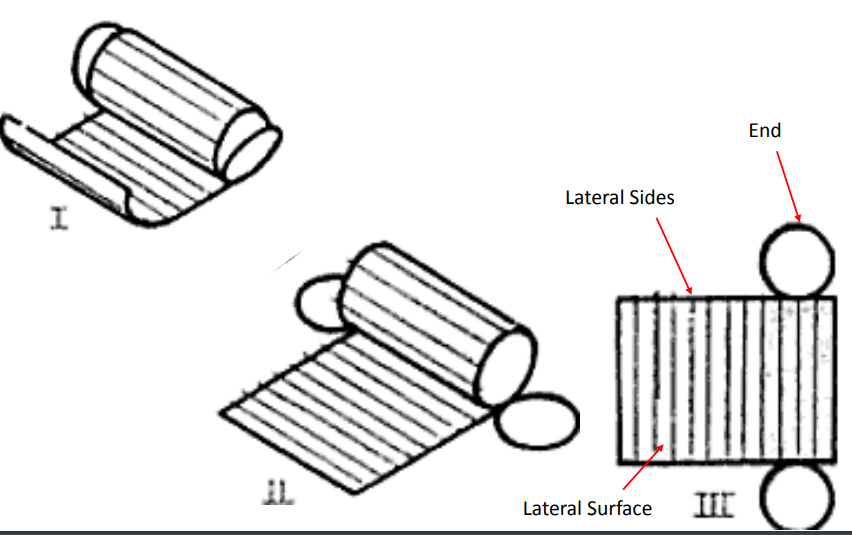
3. Explain the development of a lateral surface of a Cylinder?
The development of the lateral surfaces of the objects only are shown. The base and top are cut to the required geometrical shape and fastened suitably.
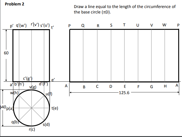
Example: Draw the development of the complete surface of a cylindrical drum. Diameter is 40 mm
and height 60mm
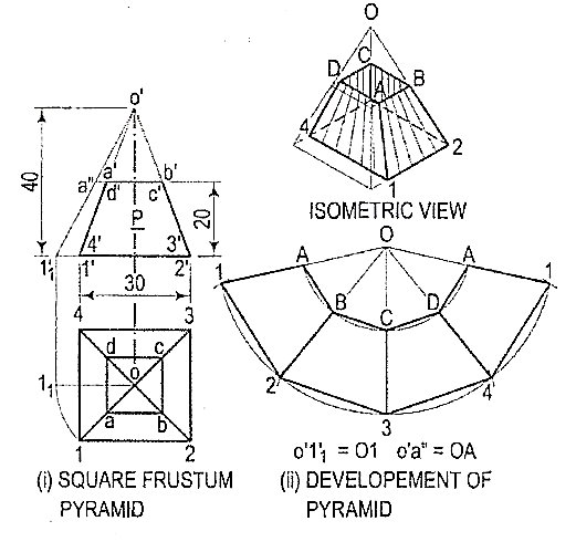
4. Explain with a diagram the development of the lateral surface of the frustum of a square pyramid?
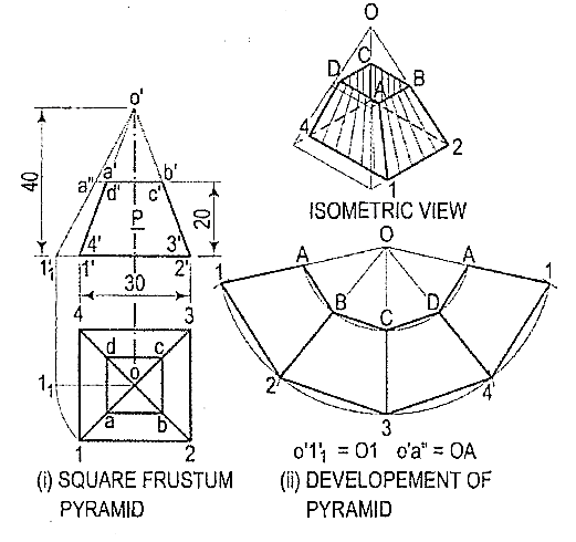
A frustum of a pyramid is a polyhedron enclosed by the lateral surface and the base of the pyramid. If the pyramid is a regular right pyramid, the frustum has congruent isosceles trapezoids as lateral faces.
i) Determine the position of the apex. None of the lines in the front view shows the true length of the slant edge. Therefore, draw the top view and make any one line (for the slant edge) horizontal, i.e., parallel to xy and determine the true length o'1 '1. Through a', draw a line parallel to the base and obtain the true length o'a".
(ii) With O as centre and radius o'1 '1, draw an arc and obtain the development of the lateral surface of the whole pyramid [fig. 9(ii)].
(iii) With centre O and radius o' a", draw an arc cutting O1, O2 etc. at points, B etc. respectively.
(iv) Draw lines AB, BC, CD and DA and complete the required development. Note that these lines are respectively parallel to lines 1-2, 2-3 etc.
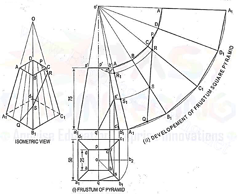
3.A frustum of a square pyramid has its base 50 mm side; top 25 mm side and height 75 mm. Draw the development of its lateral surface.
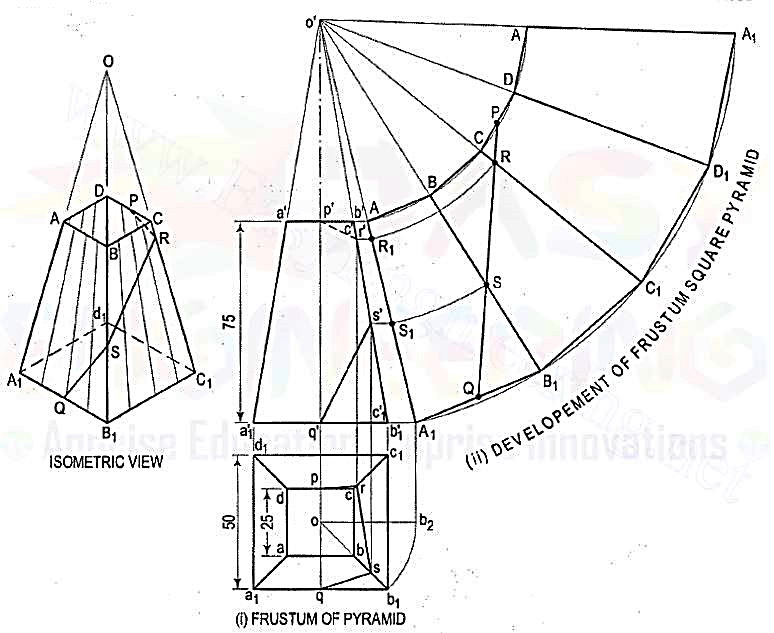
(i) Mark the mid-point P of CD and Q of A1B1. Draw a line joining P and Q and cutting CC1 at R and BB1 at S. Transfer these points to the front view and the top view. For example, with o' as centre and radius o'R, draw an arc cuttingo' A1 at R1. Through R1, draw a line parallel to the base and cutting c'c'1 at r'.Project r' to r on cc1 in the top view. r' and r are the projections of R.
(ii) Similarly, obtain s' and s on b'b'1 and bb1 respectively. Draw lines pr, rs and sq which will show the top view of the line PQ. p'r's'q' will be the path of the line PQ in the front view.
5. What do you understand by the Development of Transition Pieces, give an example?
Transition Pieces are usually made to connect two different shaped objects (e.g., round pipes to square pipes) as often found in Ducting for Air Conditioning or Dust and Fume Extraction systems. The Development is constructed by assuming the surface to be made from a series of triangular surfaces laid side-by-side
Pipes are used in many industries to convey hot or cold fluids. When two different sizes and shapes of pipes are joined using special pipe joint which is known as transition piece. In most cases, transition pieces are composed of plane surfaces and conical surfaces, the latter being developed by triangulation.
6.How are Transition pieces applicable in Air condition systems?
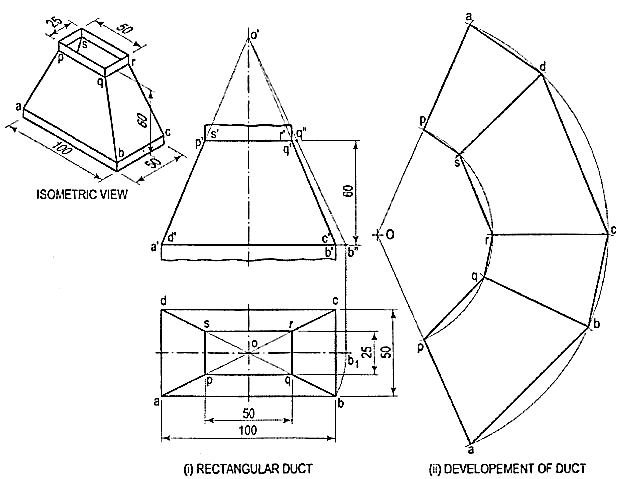
In air-conditioning system, a rectangular duct of 100 mm x 50 mm connects another rectangular duct of 50 mm x 25 mm through the transition piece. Neglecting thickness of a metal sheet, develop the lateral surface of the transition piece
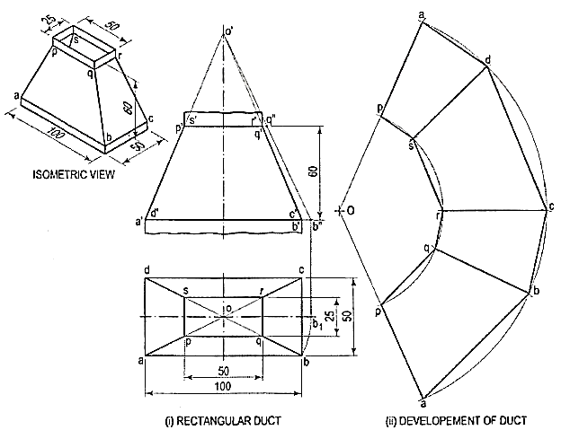
The transition piece is a frustum of a rectangular pyramid.
(i) Determine the position of the apex of the pyramid by extending a'p' and b'q' as shown. None of the lines in the front view shows the true length of the slant edge. Therefore, draw the top view and make any slant line parallel to xy and determine its true length o'b".
(ii) With O as centre and radius o'b", draw an arc and obtain the development of a whole pyramid as shown.
(iii) With O as centre and radius o'q", draw an arc cutting oa, ob, oc at points p, q, etc. respectively. Join them in sequence and complete the development as shown.
7.Define Intersection of solids?
The intersecting surfaces may be two plane surfaces or two curved surfaces of solids. The lateral surface of every solid taken as a whole is a curved surface. This surface may be made of only curved surface as in case of cylinders, cones etc. or of plane surfaces as in case of prisms, pyramids etc. In the former case, the problem is said to be on the intersection of surfaces and in the latter case, it is commonly known as the problem on interpenetration of solids. It may, however, be noted that when two solids meet or join or interpenetrate, it is the curved surfaces of the two that intersect each other.
The two solids may intersect in different ways. The axes of the solids may be parallel, inclined or perpendicular to each other. The axes may be intersecting, offset or coinciding. The type of intersection created depends on the types of geometric forms, which can be two- or three- dimensional.
PURPOSE OF INTERSECTION OF SOLIDS: Solids in real world are obtained by a combination of two or more basic solids. The intersection of solid plays an important role in designing and manufacturing of objects, especially the sheet metal objects.
8. Explain the methods to determine line of Intersection between surfaces of two interpenetrating solid?
(1) line method: A number of lines are drawn on the lateral surface of one of the solids and in the region of the line of intersection. Points of intersection of these lines with the surface of the other solid are then located. These points will obviously lie on the required line of intersection. They are more easily located from the view in which the lateral surface of the second solid appears edgewise (i.e., as a line). The curve drawn through these points will be the line of intersection.
(2) Cutting-plane method: The two solids are assumed to be cut by a series of cutting planes. The cutting planes may be vertical (i.e., perpendicular to the H.P.), edgewise (i.e., perpendicular to the V.P.) or oblique. The cutting planes are so selected as to cut the surface of one of the solids in straight lines and that of the other in straight lines or circles.
9. Explain the Intersection in Cones and Cylinders?
The intersection is explained with an example
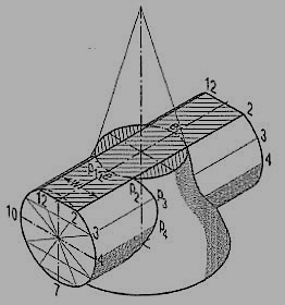
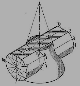
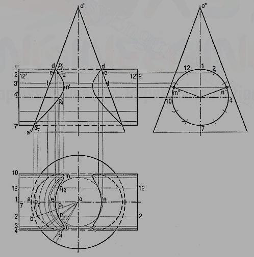
1.A vertical cone, diameter of base 75 mm and axis 100 mm Jong, is completely penetrated by a cylinder of 45 mm diameter. The axis of the cylinder is parallel to the H.P. And the V.P. And intersects the axis of the cone at a point 28 mm above the base. Draw the projections of the solids showing curves of intersection.
(a) Cutting-plane method (fig. 11 and fig. 12):
(i) Draw lines dividing the surface of the cylinder into twelve equal parts.
(ii) Assume a horizontal cutting plane passing through say, point 2 (fig. 11). The section of the cylinder will be a rectangle of width w (i.e., the line 2-12), while that of the cone will be a circle of diameter ee. These two sections intersect at points p2 and p12. These sections are clearly indicated in the top view by the rectangle 2-2-12-12 and the circle of diameter ee (fig. 12).
In the front view, the cutting plane is seen as a line coinciding with 2'2'. Points p2and p12 when projected on the line 2' 2'(with which the line 12'-12' coincides) will give a point p'2 (with which p'12 will coincide). Then p'2 and p'12 are the points on the curve of intersection.
(iii) To obtain the points systematically, draw circles with centre o and diameters dd,ee, ff etc. cutting lines through 1, 2 and12, 3 and 11 etc. at points p1, p2 andP12, P3 and P11 etc.
(iv) Project these points to the corresponding lines in the front view. Two more key points at which the curve changes direction must also be located. Their positions are determined from the side view. They are the points of nearest approach viz. m" and n" at which, lines drawn from the centre of the circle (i.e., the axis of the cylinder) and perpendicular to the extreme generators of the cone, cut the circle.
(v) Project these points to m' and n' in the front view and to m and n in the top view on the corresponding lines. Draw curves through these points in both the views. The back curve in the front view will coincide with the front curve. In. The top view a part of the curve will lie hidden and hence, it will be dotted. Draw similar curves on the right-hand side of the axis of the cone.
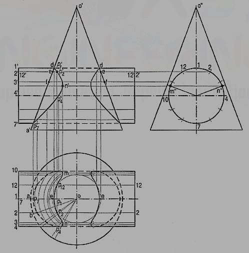
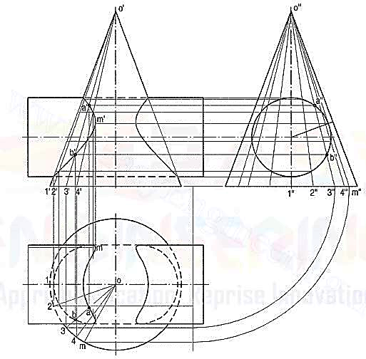
(b) Line method (fig. 13): The surface of the cylinder is a circle in the side view.
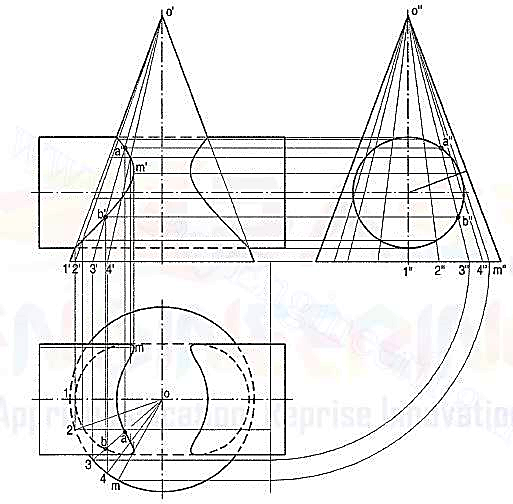
(i) Hence, draw a number of lines (representing generators of the cone) o ‘’1’’ o’’2" etc. in the region of the circle and symmetrical on both sides of the axis. Points where these lines intersect the circle, lie on the curve of intersection.
(ii) To project them in the front and top views, first project the lines in both the views and then, locate the positions of these points on them. Let us take the line o"3" in the side view. Locate its position o3 in the top view as shown and project its front view o'3'. Project points a" and b" to points a' and b' on o'3' and from there, to a and b on o3.
(iii) Project all points in the same manner and draw the required curves through them. This method is a type of cutting-plane method in which cutting planes pass through the apex and are parallel to the axis of the cylinder.
10.How is the intersection of Spheres different from Prisms with example?
Intersection of Sphere and Prism:
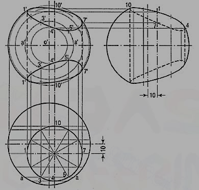
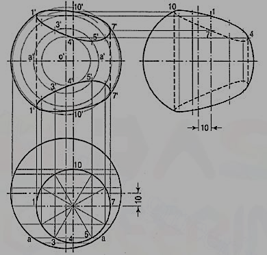
A hole of 50 mm diameter is drilled through a sphere of 75 mm diameter. The axis of the hole is 70 mm away from the centre of the sphere. Draw three views of the sphere when a vertical plane containing the centre of the sphere and the axis of the hole is inclined at 60° to the V.P.
(i) Draw the top view of the sphere and show the circle for the hole in the required position.
(ii) Project the front view and the side view. Divide the circle for the hole into twelve equal parts.
(iii) Assume many cutting planes parallel to the V.P. The sections of the sphere will be circles, while the hole will be cut in straight lines. Intersection of the circles with corresponding lines will give points on the curves.
(iv) Let us take a section plane passing through points 3 and 5. The section of the sphere will be a circle of diameter aa. The lines through 3 and 5 intersect this circle at points 3' and 5' which lie on the curve. Obtain the twelve points in the same manner. Also plot the key points at which the section through the centre of the sphere is cut by the lines of the hole. Draw curves through all the points. Project the points on the side view horizontally from the front view on corresponding lines of the hole and draw curves through them.
UNIT 4
Development of Surfaces
- What do you understand by Development of surfaces, explain its importance?
“The development of surface of an object means the unrolling and unfolding of all surfaces of the object on a plane.” “If the surface of a solid is laid out on a plain surface, the shape thus obtained is called the development of that solid.” In other words, the development of a solid is the shape of a plain sheet that by proper folding could be converted into the shape of the concerned solid.
The knowledge of development of surfaces is essential in many industries such as automobile, aircraft, ship building, packaging and sheet-metal work. In construction of boilers, bins, process-vessels, hoppers, funnels, chimneys etc., the plates are marked and cut according to the developments which, when folded, form the desired objects. The form of the sheet obtained by laying all the outer surfaces of the solid with suitable allowances for the joints is known as pattern.
Importance of Development: Knowledge of development is very useful in sheet metal work, construction of storage vessels, chemical vessels, boilers, and chimneys. Such vessels are manufactured from plates that are cut according to these developments and then properly bend into desired shaped. The joints are then welded or riveted.
2. Briefly explain the principle methods of development of surfaces?
Principle of Development: Every line on the development should show the true length of the corresponding line on the surface which is developed.
Methods of Development:
(a) Parallel-line development
(b) Radial-line development
(c) Triangulation development
(d) Approximate development
Parallel-line Method: It is used for developing prisms and single curved surfaces like cylinders, in which all the edges/generation of lateral surfaces are parallel in each other.
Radial-line Method: It is employed for pyramids and single curved surfaces like cones in which the apex is taken as centre and the slant edge or generator as radius of its development.
Triangulation Method: It is used for developing transition pieces.
Approximate Method: It is employed for double curved surfaces like spheres, as they are theoretically not possible to develop. The surface of the sphere is developed by approximate method.
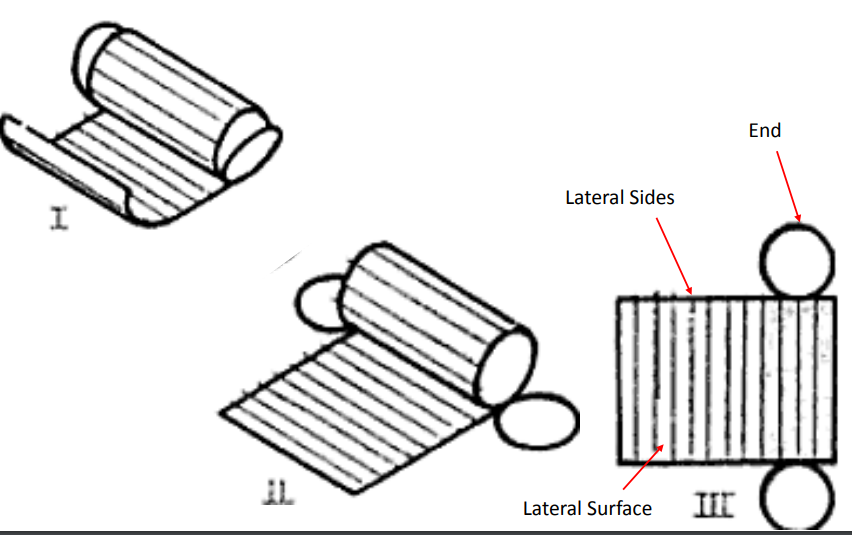
3. Explain the development of a lateral surface of a Cylinder?
The development of the lateral surfaces of the objects only are shown. The base and top are cut to the required geometrical shape and fastened suitably.
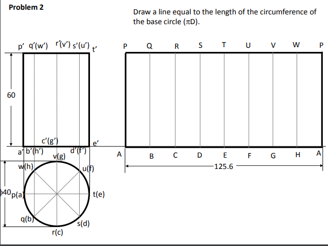
Example: Draw the development of the complete surface of a cylindrical drum. Diameter is 40 mm
and height 60mm
4. Explain with a diagram the development of the lateral surface of the frustum of a square pyramid?
A frustum of a pyramid is a polyhedron enclosed by the lateral surface and the base of the pyramid. If the pyramid is a regular right pyramid, the frustum has congruent isosceles trapezoids as lateral faces.
i) Determine the position of the apex. None of the lines in the front view shows the true length of the slant edge. Therefore, draw the top view and make any one line (for the slant edge) horizontal, i.e., parallel to xy and determine the true length o'1 '1. Through a', draw a line parallel to the base and obtain the true length o'a".
(ii) With O as centre and radius o'1 '1, draw an arc and obtain the development of the lateral surface of the whole pyramid [fig. 9(ii)].
(iii) With centre O and radius o' a", draw an arc cutting O1, O2 etc. at points, B etc. respectively.
(iv) Draw lines AB, BC, CD and DA and complete the required development. Note that these lines are respectively parallel to lines 1-2, 2-3 etc.
3.A frustum of a square pyramid has its base 50 mm side; top 25 mm side and height 75 mm. Draw the development of its lateral surface.
(i) Mark the mid-point P of CD and Q of A1B1. Draw a line joining P and Q and cutting CC1 at R and BB1 at S. Transfer these points to the front view and the top view. For example, with o' as centre and radius o'R, draw an arc cuttingo' A1 at R1. Through R1, draw a line parallel to the base and cutting c'c'1 at r'.Project r' to r on cc1 in the top view. r' and r are the projections of R.
(ii) Similarly, obtain s' and s on b'b'1 and bb1 respectively. Draw lines pr, rs and sq which will show the top view of the line PQ. p'r's'q' will be the path of the line PQ in the front view.
5. What do you understand by the Development of Transition Pieces, give an example?
Transition Pieces are usually made to connect two different shaped objects (e.g., round pipes to square pipes) as often found in Ducting for Air Conditioning or Dust and Fume Extraction systems. The Development is constructed by assuming the surface to be made from a series of triangular surfaces laid side-by-side
Pipes are used in many industries to convey hot or cold fluids. When two different sizes and shapes of pipes are joined using special pipe joint which is known as transition piece. In most cases, transition pieces are composed of plane surfaces and conical surfaces, the latter being developed by triangulation.
6.How are Transition pieces applicable in Air condition systems?
In air-conditioning system, a rectangular duct of 100 mm x 50 mm connects another rectangular duct of 50 mm x 25 mm through the transition piece. Neglecting thickness of a metal sheet, develop the lateral surface of the transition piece
The transition piece is a frustum of a rectangular pyramid.
(i) Determine the position of the apex of the pyramid by extending a'p' and b'q' as shown. None of the lines in the front view shows the true length of the slant edge. Therefore, draw the top view and make any slant line parallel to xy and determine its true length o'b".
(ii) With O as centre and radius o'b", draw an arc and obtain the development of a whole pyramid as shown.
(iii) With O as centre and radius o'q", draw an arc cutting oa, ob, oc at points p, q, etc. respectively. Join them in sequence and complete the development as shown.
7.Define Intersection of solids?
The intersecting surfaces may be two plane surfaces or two curved surfaces of solids. The lateral surface of every solid taken as a whole is a curved surface. This surface may be made of only curved surface as in case of cylinders, cones etc. or of plane surfaces as in case of prisms, pyramids etc. In the former case, the problem is said to be on the intersection of surfaces and in the latter case, it is commonly known as the problem on interpenetration of solids. It may, however, be noted that when two solids meet or join or interpenetrate, it is the curved surfaces of the two that intersect each other.
The two solids may intersect in different ways. The axes of the solids may be parallel, inclined or perpendicular to each other. The axes may be intersecting, offset or coinciding. The type of intersection created depends on the types of geometric forms, which can be two- or three- dimensional.
PURPOSE OF INTERSECTION OF SOLIDS: Solids in real world are obtained by a combination of two or more basic solids. The intersection of solid plays an important role in designing and manufacturing of objects, especially the sheet metal objects.
8. Explain the methods to determine line of Intersection between surfaces of two interpenetrating solid?
(1) line method: A number of lines are drawn on the lateral surface of one of the solids and in the region of the line of intersection. Points of intersection of these lines with the surface of the other solid are then located. These points will obviously lie on the required line of intersection. They are more easily located from the view in which the lateral surface of the second solid appears edgewise (i.e., as a line). The curve drawn through these points will be the line of intersection.
(2) Cutting-plane method: The two solids are assumed to be cut by a series of cutting planes. The cutting planes may be vertical (i.e., perpendicular to the H.P.), edgewise (i.e., perpendicular to the V.P.) or oblique. The cutting planes are so selected as to cut the surface of one of the solids in straight lines and that of the other in straight lines or circles.
9. Explain the Intersection in Cones and Cylinders?
The intersection is explained with an example
1.A vertical cone, diameter of base 75 mm and axis 100 mm Jong, is completely penetrated by a cylinder of 45 mm diameter. The axis of the cylinder is parallel to the H.P. And the V.P. And intersects the axis of the cone at a point 28 mm above the base. Draw the projections of the solids showing curves of intersection.
(a) Cutting-plane method (fig. 11 and fig. 12):
(i) Draw lines dividing the surface of the cylinder into twelve equal parts.
(ii) Assume a horizontal cutting plane passing through say, point 2 (fig. 11). The section of the cylinder will be a rectangle of width w (i.e., the line 2-12), while that of the cone will be a circle of diameter ee. These two sections intersect at points p2 and p12. These sections are clearly indicated in the top view by the rectangle 2-2-12-12 and the circle of diameter ee (fig. 12).
In the front view, the cutting plane is seen as a line coinciding with 2'2'. Points p2and p12 when projected on the line 2' 2'(with which the line 12'-12' coincides) will give a point p'2 (with which p'12 will coincide). Then p'2 and p'12 are the points on the curve of intersection.
(iii) To obtain the points systematically, draw circles with centre o and diameters dd,ee, ff etc. cutting lines through 1, 2 and12, 3 and 11 etc. at points p1, p2 andP12, P3 and P11 etc.
(iv) Project these points to the corresponding lines in the front view. Two more key points at which the curve changes direction must also be located. Their positions are determined from the side view. They are the points of nearest approach viz. m" and n" at which, lines drawn from the centre of the circle (i.e., the axis of the cylinder) and perpendicular to the extreme generators of the cone, cut the circle.
(v) Project these points to m' and n' in the front view and to m and n in the top view on the corresponding lines. Draw curves through these points in both the views. The back curve in the front view will coincide with the front curve. In. The top view a part of the curve will lie hidden and hence, it will be dotted. Draw similar curves on the right-hand side of the axis of the cone.
(b) Line method (fig. 13): The surface of the cylinder is a circle in the side view.
(i) Hence, draw a number of lines (representing generators of the cone) o ‘’1’’ o’’2" etc. in the region of the circle and symmetrical on both sides of the axis. Points where these lines intersect the circle, lie on the curve of intersection.
(ii) To project them in the front and top views, first project the lines in both the views and then, locate the positions of these points on them. Let us take the line o"3" in the side view. Locate its position o3 in the top view as shown and project its front view o'3'. Project points a" and b" to points a' and b' on o'3' and from there, to a and b on o3.
(iii) Project all points in the same manner and draw the required curves through them. This method is a type of cutting-plane method in which cutting planes pass through the apex and are parallel to the axis of the cylinder.
10.How is the intersection of Spheres different from Prisms with example?
Intersection of Sphere and Prism:
A hole of 50 mm diameter is drilled through a sphere of 75 mm diameter. The axis of the hole is 70 mm away from the centre of the sphere. Draw three views of the sphere when a vertical plane containing the centre of the sphere and the axis of the hole is inclined at 60° to the V.P.
(i) Draw the top view of the sphere and show the circle for the hole in the required position.
(ii) Project the front view and the side view. Divide the circle for the hole into twelve equal parts.
(iii) Assume many cutting planes parallel to the V.P. The sections of the sphere will be circles, while the hole will be cut in straight lines. Intersection of the circles with corresponding lines will give points on the curves.
(iv) Let us take a section plane passing through points 3 and 5. The section of the sphere will be a circle of diameter aa. The lines through 3 and 5 intersect this circle at points 3' and 5' which lie on the curve. Obtain the twelve points in the same manner. Also plot the key points at which the section through the centre of the sphere is cut by the lines of the hole. Draw curves through all the points. Project the points on the side view horizontally from the front view on corresponding lines of the hole and draw curves through them.
