Unit - 4
Fibre Optics
Q1) Explain optical fibre as a dielectric wave guide? Also define term Meridional rays and Skew Rays?
A1)
Light propagates inside an optical fibre by virtue of multiple TIRs at the core-cladding interface. The refractive index of the core glass is greater than that of the cladding. This meets the first condition for a TIR. All the light energy that is launched into the optical fibre through its tip does not get guided along the fibre. Only those light rays propagate through the fibre which is launched into the fibre at such an angle that the refracted ray inside the core of the optical fibre is incident on the core-cladding interface at an angle greater than the critical angle of the core with respect to the cladding.
1. Optical fibre is basically a solid glass rod. The diameter of rod is so small that it looks like a fibre.
2. Optical fibre is a dielectric waveguide. The light travels like an electromagnetic wave inside the waveguide. The dielectric waveguide is different from a metallic waveguide which is used at microwave and millimeter wave frequencies.
3. In a metallic waveguide, there is a complete shielding of electromagnetic radiation but in an optical fibre the electromagnetic radiation is not just confined inside the fibre but also extends outside the fibre.
4. The light gets guided inside the structure, through the basic phenomenon of total internal reflection.
5. The optical fibre consists of two concentric cylinders; the inside solid cylinder is called the core and the surrounding shell is called the cladding. (See Fig 12)
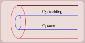
Figure: Schematic of an optical fibre
6. For the light to propagate inside the fibre through total internal reflections at core-cladding interface, the refractive index of the core must be greater than the refractive index of the cladding. That is n1>n2.
SIMPLE RAY MODEL

Figure: (optical fibre with core, cladding and total internally reflected ray)
For propagation of light inside the core there are two possibilities.
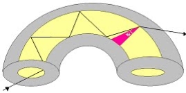
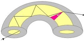
1. A light ray is launched in a plane containing the axis of the fibre. We can then see the light ray after total internal reflection travels in the same plane i.e., the ray is confined to the plane in which it was launched and never leave the plane. In this situation the rays will always cross the axis of the fibre. These are called the Meridional rays.
2. The other possibility is that the ray is not launched in a plane containing the axis of the fibre.
For example if the ray is launched at some angle such that it does not intersect the axis of the fibre, then after total internal reflection it will go to some other plane. We can see that in this situation the ray will never intersect the axis of the fibre. The ray essentially will spiral around the axis of fibre. These rays are called the Skew rays.
So it can be concluded that if the light is to propagate inside an optical fibre it could be through two types of rays
a) Meridional rays: The rays which always pass through the axis of fibre giving high optical intensity at the center of the core of the fibre.
b) Skew Rays: The rays which never intersect the axis of the fibre, giving low optical intensity at the center and high intensity towards the rim of the fibre.
Q2) Explain Propagation of Meridional Rays.
A2)
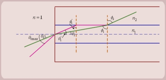
Figure: Propagation of Meridional Rays
1. Let us consider figure. A ray is launched from outside (air) at an angle θ0 , from the axis of the fibre.
The question is, under what conditions the ray is ultimately guided inside the core due to total internal reflections at the core cladding boundary.
2. Let the ray makes an angle θ1 with the axis of the fibre inside the core, and let the ray make an angle ϕ1 with core -cladding interface. Let ϕ2 be the angle of refraction in the cladding.
If ϕ1 < critical angle the ray is refracted in cladding. The ray which goes to cladding is lost and is not useful for communication. The ray which is confined to the core is useful for optical communication.
3. Now as we increase the launching angle θ0, the angle θ1 also increases. Since θ1 + ϕ1 = 
ϕ1 decreases and at some point becomes less than the critical angle. When ϕ1 equals the critical angle, ϕ2 equals  . The maximum launching angle then corresponds to ϕ2 =
  .
.
4. Let us apply Snell’s law at the launching point and at the core-cladding interface for the maximum launching angle θ0max. For this case let θ1 = θ’1 and ϕ1 = ϕ’1
We then have
 (since
  )
)

Now,
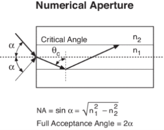
So the sine of the maximum angle at which the ray will be guided inside the fibre is given by square root of the difference of squares of the refractive indices of the core and cladding. The quantity sin 0max is called the numerical aperture of an optical fibre. The NA is a measure of the power launching efficiently of an optical fibre.
Q3) Explain total internal reflection.
A3)
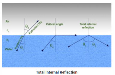
The phenomenon which occurs when the light rays travel from a more optically denser medium to a less optically denser medium.
Consider the following situation.
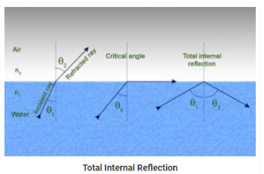
A ray of light passes from a medium of water to that of air. Light ray will be refracted at the junction separating the two media. Since it passes from a medium of a higher refractive index to that having a lower refractive index, the refracted light ray bends away from the normal. At a specific angle of incidence, the incident ray of light is refracted in such a way that it passes along the surface of the water. This particular angle of incidence is called the critical angle. Here the angle of refraction is 90 degrees. When the angle of incidence is greater than the critical angle, the incident ray is reflected back to the medium. We call this phenomenon total internal reflection.
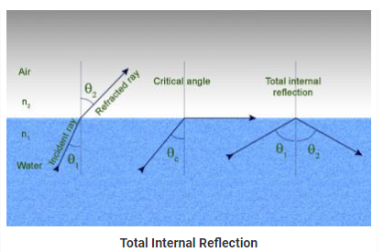

Notations Used in The Total Internal Reflection Formula and Critical Angle
- r is the angle of refraction
- i is the angle of incidence
- n1 is the refractive index in medium 1
- n2 is the refractive index in medium 2
- Ө is the critical angle
Following are the two conditions of total internal reflection:
- The light ray moves from a more denser medium to less dense medium.
- The angle of incidence must be greater than the critical angle.
When the incident ray falls on the cladding, it suffers total internal reflection as the angle formed by the ray is greater than the critical angle. Optical fibres have revolutionised the speed with which signals are transferred, not only across cities but across countries and continents making telecommunication one of the fastest modes of information transfer. Optical fibres are also used in endoscopy.
Q4) What is Numerical aperture?
A4)
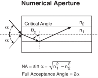
Numerical Aperture (NA)
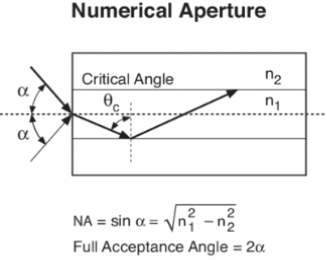
The Numerical Aperture (NA) of a fibre is defined as the sine of the largest angle an incident ray can have for total internal reflectance in the core. Rays launched outside the angle specified by a fibber’s NA will excite radiation modes of the fibre. A higher core index, with respect to the cladding, means larger NA. However, increasing NA causes higher scattering loss from greater concentrations of dopant. A fibre's NA can be determined by measuring the divergence angle of the light cone it emits when all its modes are excited.
Qualitatively, NA is a measure of the light gathering ability of a fibre. It also indicates how easy it is to couple light into a fibre.
Q5) Explain Losses associated with optical fibres.
A5)
Attenuation is the loss of optical power as light travels along the fibre, caused by absorption, scattering, and bending losses. Signal attenuation is defined as the ratio of optical input power (Pi) to the optical output power (Po). The following equation defines signal attenuation as a unit of length:

Factors of Attenuation
Absorption Loss
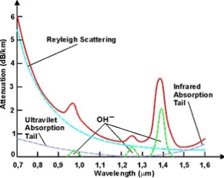
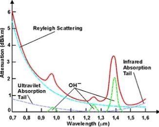
Absorption is caused by basic fibre-material properties as well as the impurity of transition metals and the presence of (OH-). Absorption in the ultraviolet region is caused by electronic absorption bands. The main cause of Absorption in the infrared region is the characteristic vibration frequency of atomic bonds.
If during fabrication transition metal impurities are introduced in the fibre material, such as iron, nickel, and chromium. Presence of (OH-) also increase absorption of light.
The amount of water (OH-) impurities present in a fibre should be less than a few parts per billion. Fibre attenuation caused by extrinsic absorption is affected by the level of impurities (OH-) present in the fibre. If the amount of impurities in a fibre is reduced, then fibre attenuation is reduced.
Scattering Loss
Scattering losses are caused by the interaction of light with density fluctuations within a fibre. Density changes are produced when optical fibres are manufactured. During manufacturing, regions of higher and lower molecular density areas, relative to the average density of the fibre, are created. Light traveling through the fibre interacts with the density areas and light is then partially scattered in all directions.
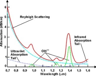
According to Rayleigh scattering loss is inversely proportional to the fourth power of the wavelength i.e., 1 / l4.
Microbend Loss
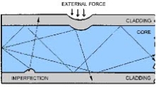
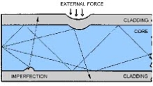
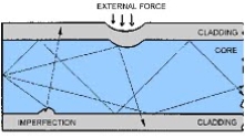
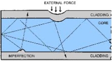
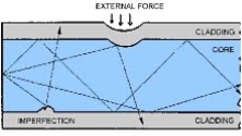
Microbend losses are small microscopic bends of the fibre axis that occur mainly when a fibre is cabled. These bends occur due to external forces, uneven coating applications and improper cabling procedures. Microbends change the path that propagating modes take, as shown in figure.
Macrobend Loss
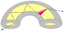
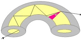
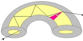
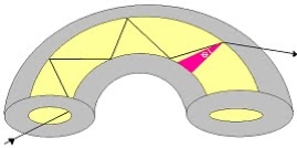
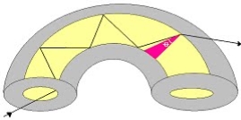
Macrobend loss are bends having a large radius of curvature relative to the fibre diameter.
Mode Coupling Loss
Coupling loss in fibre optics refers to the power loss that occurs when coupling light from one optical device or medium to another
Q6) Explain Step and graded index fibres
A6)
The types of optical fibres depend on the refractive index, materials used, and mode of propagation of light.
The classification based on the materials used is as follows:
- Plastic Optical Fibres: The polymethylmethacrylate is used as a core material for the transmission of light.
Example:
Core: polymethyl methacrylate : Cladding: Co- Polymer
Core: Polystyrene : Cladding: Methyl methacrylate
- Glass Fibres: It consists of extremely fine glass fibres.
Example:
Core: SiO2 Cladding: SiO2
Core: GeO2- SiO2 Cladding: SiO2
The classification based on the mode of propagation of light is as follows:
Mode of propagation:
Light propagates as electromagnetic waves through an optical fibre. All waves, having ray directions above the critical angle will be trapped within the fibre due to total internal reflection. However, all such waves do not propagate through the fibre. Only certain ray directions are allowed to propagate. The allowed directions correspond to the modes of the fibre. In simple terms, modes can be visualized as the possible number of paths of light in an optical fibre.
- Single-Mode Fibres:
These fibres are used for long-distance transmission of signals. In general, the single-mode fibres are step-index fibres. These types of fibres are made from doped silica. It has a very small core diameter so that it can allow only one mode of propagation and hence called single-mode fibres.
The cladding diameter must be very large compared to the core diameter. Thus in the case of single-mode fibre, the optical loss is very much reduced. The structure of a single-mode fibre is given below.
Structure:
Core diameter: 5-10μm
Cladding diameter: Generally around 125μm
Protective layer: 250 to 1000μm
Numerical aperture: 0.08 to 0.10
Bandwidth: More than 50MHz km.
Application:
Because of high bandwidth, they are used in long-haul communication systems.
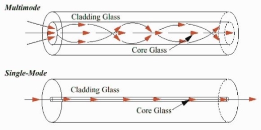
Figure: Single Mode and Multimode Fibre
- Multimode Fibres:
These fibres are used for short-distance transmission of signals. The multi-mode fibres are useful in manufacturing both for step-index and graded-index fibres. The multi-mode fibres are made by multi-component glass compounds such as Glass – Clad Glass, Silica – Clad – Silica, doped silica, etc. Here the core diameter is very large compared to single-mode fibres, so that it can allow many modes to propagate through it and hence called Multi-mode fibres. The cladding diameter is also larger than the diameter of the single-mode fibres. The structure of the multimode fibre is as shown in the figure above.
Structure:
Core diameter : 50-350μm
Cladding diameter : 125μm - 500μm
Protective layer : 250 to 1100μm
Numerical aperture : 0.12 to 0.5
Bandwidth : Less than 50MHz km.
The total number of modes possible for such an electromagnetic waveguide is

Here
d = core diameter
NA = numerical aperture
 = Optical wavelength
Application:
Because of its less bandwidth, it is very useful in short-haul communication systems.
The classification based on the refractive index is as follows:
- Step Index Single-mode Fibres
It consists of a core surrounded by the cladding, which has a single uniform index of refraction. Step index-single mode fibres: A single-mode step-index fibre consists of a very thin core of uniform refractive index surrounded by a cladding of refractive index lower than that of the core. The refractive index abruptly changes at the core-cladding boundary. Light travels along a side path, i.e., along the axis only. So zero-order modes are supported by Single Mode Fibre.
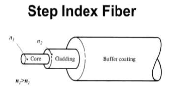
Figure: Step Index Single-mode Fibres
- Step index-Multimode fibres
A multimode step-index fibre consists of a core of uniform refractive index surrounded by a cladding of refractive index lower than that of the core. The refractive index abruptly changes at the core-cladding boundary. The core is of large diameter. Light follows zigzag paths inside the fibre. Many such zigzag paths of propagation are permitted in Multi-Mode Fibre. The Numerical Aperture of a Multi-mode fibre is larger as the core diameter of the fibre is larger
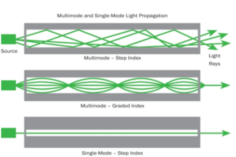
Figure: Step index-Multimode fibres
- Graded Index Fibres:
The refractive index of the optical fibre decreases as the radial distance from the fibre axis increases. GRIN fibre is one in which the refractive index varies radially, decreasing continuously in a parabolic manner from the maximum value of n1, at the center of the core to a constant value of n2 at the core-cladding interface.
In graded-index fibre, light rays travel at different speeds in different parts of the fibre because the refractive index varies throughout the fibre. Near the outer edge, the refractive index is lower. As a result, rays near the outer edge travel faster than the rays at the center of the core. Because of this, rays arrive at the end of the fibre at approximately the same time. In effect light rays that arrive at the end of the fibre are continuously refocused as they travel down the fibre. All rays take the same amount of time in traversing the fibre. This leads to small pulse dispersion.
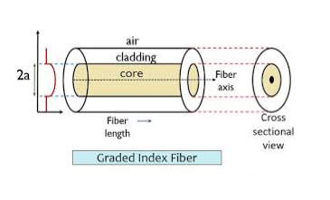
Figure: Graded Index Fibres
The pulse dispersion is given by

Here

For a parabolic index fibre, the pulse dispersion is reduced by a factor of about 200 in comparison to step-index fibre. It is because of this reason that first and second-generation optical communication systems used near parabolic index fibres.
Q7) Write some application of optical fibres.
A7)
- Medical
Used as light guides, imaging tools and also as lasers for surgeries
- Defence/Government
Used as hydrophones for seismic waves and SONAR, as wiring in aircraft, submarines and other vehicles and also for field networking
- Data Storage
Used for data transmission
- Telecommunications
Fibre is laid and used for transmitting and receiving purposes
- Networking
Used to connect users and servers in a variety of network settings and help increase the speed and accuracy of data transmission
- Industrial/Commercial
Used for imaging in hard to reach areas, as wiring where EMI is an issue, as sensory devices to make temperature, pressure and other measurements, and as wiring in automobiles and in industrial settings
- Broadcast/CATV
Broadcast/cable companies are using fibre optic cables for wiring CATV, HDTV, internet, video on-demand and other applications
Fibre optic cables are used for lighting and imaging and as sensors to measure and monitor a vast array of variables. Fibre optic cables are also used in research and development and testing across all the above-mentioned industries.
Q8) Explain “V Number”.
A8)
“V Number”
The Normalized Frequency Parameter of a fibre, also called the V number, is a useful specification. Many fibre parameters can be expressed in terms of V, such as: the number of modes at a given wavelength, mode cut off conditions, and propagation constants. For example, the number of guided modes in a step index multimode fibre is given by V2/2, and a step index fibre becomes single-mode for a given wavelength when V<2.405. Mathematically, V=2 π·NA·a/λ where “a” is the fibre core radius.
V – number determines how many modes a fibre can support, it is given by,

Where d is the diameter of the core, l is the wavelength of light used and NA is the numerical aperture of the fibre.

Or

If V ≤ 2.405, then the fibre is single mode fibre (SMF)
If V > 2.405, then the fibre is multimode fibre (MMF)
Number of Modes traveling in Fibre
The total number of modes traveling in a fibre depends on the V – Number and is related as:
For Step Index Fibre:

For Graded Index Fibre: 
Q9) Explain graded index fibre.
A9)
The refractive index of the optical fibre decreases as the radial distance from the fibre axis increases. GRIN fibre is one in which the refractive index varies radially, decreasing continuously in a parabolic manner from the maximum value of n1, at the center of the core to a constant value of n2 at the core-cladding interface.
In graded-index fibre, light rays travel at different speeds in different parts of the fibre because the refractive index varies throughout the fibre. Near the outer edge, the refractive index is lower. As a result, rays near the outer edge travel faster than the rays at the center of the core. Because of this, rays arrive at the end of the fibre at approximately the same time. In effect light rays that arrive at the end of the fibre are continuously refocused as they travel down the fibre. All rays take the same amount of time in traversing the fibre. This leads to small pulse dispersion.
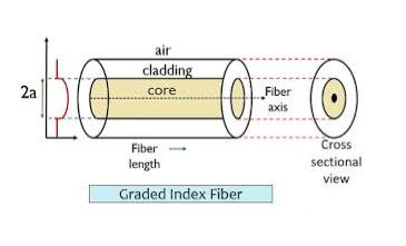
Figure: Graded Index Fibres
The pulse dispersion is given by

Here

For a parabolic index fibre, the pulse dispersion is reduced by a factor of about 200 in comparison to step-index fibre. It is because of this reason that first and second-generation optical communication systems used near parabolic index fibres.
Q10) Write short note on microbend and macrobend loss.
A10)
Microbend Loss
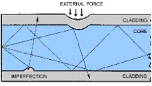
Microbend losses are small microscopic bends of the fibre axis that occur mainly when a fibre is cabled. These bends occur due to external forces, uneven coating applications and improper cabling procedures. Microbends change the path that propagating modes take, as shown in figure.
Macrobend Loss
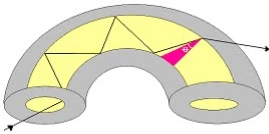
Macrobend loss are bends having a large radius of curvature relative to the fibre diameter.
Unit - 4
Fibre Optics
Q1) Explain optical fibre as a dielectric wave guide? Also define term Meridional rays and Skew Rays?
A1)
Light propagates inside an optical fibre by virtue of multiple TIRs at the core-cladding interface. The refractive index of the core glass is greater than that of the cladding. This meets the first condition for a TIR. All the light energy that is launched into the optical fibre through its tip does not get guided along the fibre. Only those light rays propagate through the fibre which is launched into the fibre at such an angle that the refracted ray inside the core of the optical fibre is incident on the core-cladding interface at an angle greater than the critical angle of the core with respect to the cladding.
1. Optical fibre is basically a solid glass rod. The diameter of rod is so small that it looks like a fibre.
2. Optical fibre is a dielectric waveguide. The light travels like an electromagnetic wave inside the waveguide. The dielectric waveguide is different from a metallic waveguide which is used at microwave and millimeter wave frequencies.
3. In a metallic waveguide, there is a complete shielding of electromagnetic radiation but in an optical fibre the electromagnetic radiation is not just confined inside the fibre but also extends outside the fibre.
4. The light gets guided inside the structure, through the basic phenomenon of total internal reflection.
5. The optical fibre consists of two concentric cylinders; the inside solid cylinder is called the core and the surrounding shell is called the cladding. (See Fig 12)
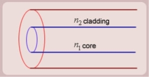
Figure: Schematic of an optical fibre
6. For the light to propagate inside the fibre through total internal reflections at core-cladding interface, the refractive index of the core must be greater than the refractive index of the cladding. That is n1>n2.
SIMPLE RAY MODEL

Figure: (optical fibre with core, cladding and total internally reflected ray)
For propagation of light inside the core there are two possibilities.
1. A light ray is launched in a plane containing the axis of the fibre. We can then see the light ray after total internal reflection travels in the same plane i.e., the ray is confined to the plane in which it was launched and never leave the plane. In this situation the rays will always cross the axis of the fibre. These are called the Meridional rays.
2. The other possibility is that the ray is not launched in a plane containing the axis of the fibre.
For example if the ray is launched at some angle such that it does not intersect the axis of the fibre, then after total internal reflection it will go to some other plane. We can see that in this situation the ray will never intersect the axis of the fibre. The ray essentially will spiral around the axis of fibre. These rays are called the Skew rays.
So it can be concluded that if the light is to propagate inside an optical fibre it could be through two types of rays
a) Meridional rays: The rays which always pass through the axis of fibre giving high optical intensity at the center of the core of the fibre.
b) Skew Rays: The rays which never intersect the axis of the fibre, giving low optical intensity at the center and high intensity towards the rim of the fibre.
Q2) Explain Propagation of Meridional Rays.
A2)
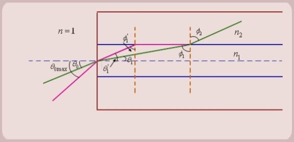
Figure: Propagation of Meridional Rays
1. Let us consider figure. A ray is launched from outside (air) at an angle θ0 , from the axis of the fibre.
The question is, under what conditions the ray is ultimately guided inside the core due to total internal reflections at the core cladding boundary.
2. Let the ray makes an angle θ1 with the axis of the fibre inside the core, and let the ray make an angle ϕ1 with core -cladding interface. Let ϕ2 be the angle of refraction in the cladding.
If ϕ1 < critical angle the ray is refracted in cladding. The ray which goes to cladding is lost and is not useful for communication. The ray which is confined to the core is useful for optical communication.
3. Now as we increase the launching angle θ0, the angle θ1 also increases. Since θ1 + ϕ1 = 
ϕ1 decreases and at some point becomes less than the critical angle. When ϕ1 equals the critical angle, ϕ2 equals  . The maximum launching angle then corresponds to ϕ2 =
  .
.
4. Let us apply Snell’s law at the launching point and at the core-cladding interface for the maximum launching angle θ0max. For this case let θ1 = θ’1 and ϕ1 = ϕ’1
We then have
 (since
  )
)

Now,
So the sine of the maximum angle at which the ray will be guided inside the fibre is given by square root of the difference of squares of the refractive indices of the core and cladding. The quantity sin 0max is called the numerical aperture of an optical fibre. The NA is a measure of the power launching efficiently of an optical fibre.
Q3) Explain total internal reflection.
A3)
The phenomenon which occurs when the light rays travel from a more optically denser medium to a less optically denser medium.
Consider the following situation.
A ray of light passes from a medium of water to that of air. Light ray will be refracted at the junction separating the two media. Since it passes from a medium of a higher refractive index to that having a lower refractive index, the refracted light ray bends away from the normal. At a specific angle of incidence, the incident ray of light is refracted in such a way that it passes along the surface of the water. This particular angle of incidence is called the critical angle. Here the angle of refraction is 90 degrees. When the angle of incidence is greater than the critical angle, the incident ray is reflected back to the medium. We call this phenomenon total internal reflection.

Notations Used in The Total Internal Reflection Formula and Critical Angle
- r is the angle of refraction
- i is the angle of incidence
- n1 is the refractive index in medium 1
- n2 is the refractive index in medium 2
- Ө is the critical angle
Following are the two conditions of total internal reflection:
- The light ray moves from a more denser medium to less dense medium.
- The angle of incidence must be greater than the critical angle.
When the incident ray falls on the cladding, it suffers total internal reflection as the angle formed by the ray is greater than the critical angle. Optical fibres have revolutionised the speed with which signals are transferred, not only across cities but across countries and continents making telecommunication one of the fastest modes of information transfer. Optical fibres are also used in endoscopy.
Q4) What is Numerical aperture?
A4)
Numerical Aperture (NA)
The Numerical Aperture (NA) of a fibre is defined as the sine of the largest angle an incident ray can have for total internal reflectance in the core. Rays launched outside the angle specified by a fibber’s NA will excite radiation modes of the fibre. A higher core index, with respect to the cladding, means larger NA. However, increasing NA causes higher scattering loss from greater concentrations of dopant. A fibre's NA can be determined by measuring the divergence angle of the light cone it emits when all its modes are excited.
Qualitatively, NA is a measure of the light gathering ability of a fibre. It also indicates how easy it is to couple light into a fibre.
Q5) Explain Losses associated with optical fibres.
A5)
Attenuation is the loss of optical power as light travels along the fibre, caused by absorption, scattering, and bending losses. Signal attenuation is defined as the ratio of optical input power (Pi) to the optical output power (Po). The following equation defines signal attenuation as a unit of length:

Factors of Attenuation
Absorption Loss
Absorption is caused by basic fibre-material properties as well as the impurity of transition metals and the presence of (OH-). Absorption in the ultraviolet region is caused by electronic absorption bands. The main cause of Absorption in the infrared region is the characteristic vibration frequency of atomic bonds.
If during fabrication transition metal impurities are introduced in the fibre material, such as iron, nickel, and chromium. Presence of (OH-) also increase absorption of light.
The amount of water (OH-) impurities present in a fibre should be less than a few parts per billion. Fibre attenuation caused by extrinsic absorption is affected by the level of impurities (OH-) present in the fibre. If the amount of impurities in a fibre is reduced, then fibre attenuation is reduced.
Scattering Loss
Scattering losses are caused by the interaction of light with density fluctuations within a fibre. Density changes are produced when optical fibres are manufactured. During manufacturing, regions of higher and lower molecular density areas, relative to the average density of the fibre, are created. Light traveling through the fibre interacts with the density areas and light is then partially scattered in all directions.
According to Rayleigh scattering loss is inversely proportional to the fourth power of the wavelength i.e., 1 / l4.
Microbend Loss
Microbend losses are small microscopic bends of the fibre axis that occur mainly when a fibre is cabled. These bends occur due to external forces, uneven coating applications and improper cabling procedures. Microbends change the path that propagating modes take, as shown in figure.
Macrobend Loss
Macrobend loss are bends having a large radius of curvature relative to the fibre diameter.
Mode Coupling Loss
Coupling loss in fibre optics refers to the power loss that occurs when coupling light from one optical device or medium to another
Q6) Explain Step and graded index fibres
A6)
The types of optical fibres depend on the refractive index, materials used, and mode of propagation of light.
The classification based on the materials used is as follows:
- Plastic Optical Fibres: The polymethylmethacrylate is used as a core material for the transmission of light.
Example:
Core: polymethyl methacrylate : Cladding: Co- Polymer
Core: Polystyrene : Cladding: Methyl methacrylate
- Glass Fibres: It consists of extremely fine glass fibres.
Example:
Core: SiO2 Cladding: SiO2
Core: GeO2- SiO2 Cladding: SiO2
The classification based on the mode of propagation of light is as follows:
Mode of propagation:
Light propagates as electromagnetic waves through an optical fibre. All waves, having ray directions above the critical angle will be trapped within the fibre due to total internal reflection. However, all such waves do not propagate through the fibre. Only certain ray directions are allowed to propagate. The allowed directions correspond to the modes of the fibre. In simple terms, modes can be visualized as the possible number of paths of light in an optical fibre.
- Single-Mode Fibres:
These fibres are used for long-distance transmission of signals. In general, the single-mode fibres are step-index fibres. These types of fibres are made from doped silica. It has a very small core diameter so that it can allow only one mode of propagation and hence called single-mode fibres.
The cladding diameter must be very large compared to the core diameter. Thus in the case of single-mode fibre, the optical loss is very much reduced. The structure of a single-mode fibre is given below.
Structure:
Core diameter: 5-10μm
Cladding diameter: Generally around 125μm
Protective layer: 250 to 1000μm
Numerical aperture: 0.08 to 0.10
Bandwidth: More than 50MHz km.
Application:
Because of high bandwidth, they are used in long-haul communication systems.
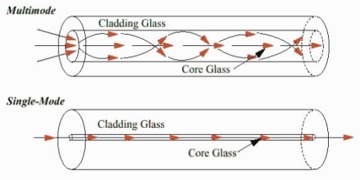
Figure: Single Mode and Multimode Fibre
- Multimode Fibres:
These fibres are used for short-distance transmission of signals. The multi-mode fibres are useful in manufacturing both for step-index and graded-index fibres. The multi-mode fibres are made by multi-component glass compounds such as Glass – Clad Glass, Silica – Clad – Silica, doped silica, etc. Here the core diameter is very large compared to single-mode fibres, so that it can allow many modes to propagate through it and hence called Multi-mode fibres. The cladding diameter is also larger than the diameter of the single-mode fibres. The structure of the multimode fibre is as shown in the figure above.
Structure:
Core diameter : 50-350μm
Cladding diameter : 125μm - 500μm
Protective layer : 250 to 1100μm
Numerical aperture : 0.12 to 0.5
Bandwidth : Less than 50MHz km.
The total number of modes possible for such an electromagnetic waveguide is

Here
d = core diameter
NA = numerical aperture
 = Optical wavelength
Application:
Because of its less bandwidth, it is very useful in short-haul communication systems.
The classification based on the refractive index is as follows:
- Step Index Single-mode Fibres
It consists of a core surrounded by the cladding, which has a single uniform index of refraction. Step index-single mode fibres: A single-mode step-index fibre consists of a very thin core of uniform refractive index surrounded by a cladding of refractive index lower than that of the core. The refractive index abruptly changes at the core-cladding boundary. Light travels along a side path, i.e., along the axis only. So zero-order modes are supported by Single Mode Fibre.
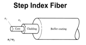
Figure: Step Index Single-mode Fibres
- Step index-Multimode fibres
A multimode step-index fibre consists of a core of uniform refractive index surrounded by a cladding of refractive index lower than that of the core. The refractive index abruptly changes at the core-cladding boundary. The core is of large diameter. Light follows zigzag paths inside the fibre. Many such zigzag paths of propagation are permitted in Multi-Mode Fibre. The Numerical Aperture of a Multi-mode fibre is larger as the core diameter of the fibre is larger
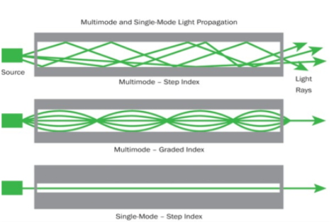
Figure: Step index-Multimode fibres
- Graded Index Fibres:
The refractive index of the optical fibre decreases as the radial distance from the fibre axis increases. GRIN fibre is one in which the refractive index varies radially, decreasing continuously in a parabolic manner from the maximum value of n1, at the center of the core to a constant value of n2 at the core-cladding interface.
In graded-index fibre, light rays travel at different speeds in different parts of the fibre because the refractive index varies throughout the fibre. Near the outer edge, the refractive index is lower. As a result, rays near the outer edge travel faster than the rays at the center of the core. Because of this, rays arrive at the end of the fibre at approximately the same time. In effect light rays that arrive at the end of the fibre are continuously refocused as they travel down the fibre. All rays take the same amount of time in traversing the fibre. This leads to small pulse dispersion.
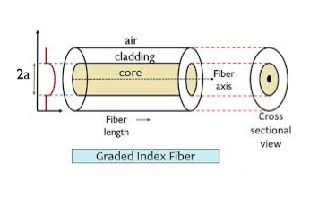
Figure: Graded Index Fibres
The pulse dispersion is given by

Here

For a parabolic index fibre, the pulse dispersion is reduced by a factor of about 200 in comparison to step-index fibre. It is because of this reason that first and second-generation optical communication systems used near parabolic index fibres.
Q7) Write some application of optical fibres.
A7)
- Medical
Used as light guides, imaging tools and also as lasers for surgeries
- Defence/Government
Used as hydrophones for seismic waves and SONAR, as wiring in aircraft, submarines and other vehicles and also for field networking
- Data Storage
Used for data transmission
- Telecommunications
Fibre is laid and used for transmitting and receiving purposes
- Networking
Used to connect users and servers in a variety of network settings and help increase the speed and accuracy of data transmission
- Industrial/Commercial
Used for imaging in hard to reach areas, as wiring where EMI is an issue, as sensory devices to make temperature, pressure and other measurements, and as wiring in automobiles and in industrial settings
- Broadcast/CATV
Broadcast/cable companies are using fibre optic cables for wiring CATV, HDTV, internet, video on-demand and other applications
Fibre optic cables are used for lighting and imaging and as sensors to measure and monitor a vast array of variables. Fibre optic cables are also used in research and development and testing across all the above-mentioned industries.
Q8) Explain “V Number”.
A8)
“V Number”
The Normalized Frequency Parameter of a fibre, also called the V number, is a useful specification. Many fibre parameters can be expressed in terms of V, such as: the number of modes at a given wavelength, mode cut off conditions, and propagation constants. For example, the number of guided modes in a step index multimode fibre is given by V2/2, and a step index fibre becomes single-mode for a given wavelength when V<2.405. Mathematically, V=2 π·NA·a/λ where “a” is the fibre core radius.
V – number determines how many modes a fibre can support, it is given by,

Where d is the diameter of the core, l is the wavelength of light used and NA is the numerical aperture of the fibre.

Or

If V ≤ 2.405, then the fibre is single mode fibre (SMF)
If V > 2.405, then the fibre is multimode fibre (MMF)
Number of Modes traveling in Fibre
The total number of modes traveling in a fibre depends on the V – Number and is related as:
For Step Index Fibre:

For Graded Index Fibre: 
Q9) Explain graded index fibre.
A9)
The refractive index of the optical fibre decreases as the radial distance from the fibre axis increases. GRIN fibre is one in which the refractive index varies radially, decreasing continuously in a parabolic manner from the maximum value of n1, at the center of the core to a constant value of n2 at the core-cladding interface.
In graded-index fibre, light rays travel at different speeds in different parts of the fibre because the refractive index varies throughout the fibre. Near the outer edge, the refractive index is lower. As a result, rays near the outer edge travel faster than the rays at the center of the core. Because of this, rays arrive at the end of the fibre at approximately the same time. In effect light rays that arrive at the end of the fibre are continuously refocused as they travel down the fibre. All rays take the same amount of time in traversing the fibre. This leads to small pulse dispersion.
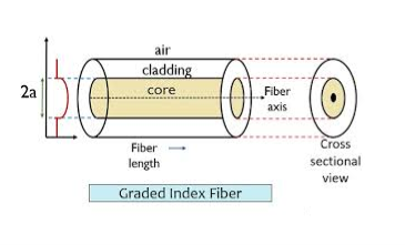
Figure: Graded Index Fibres
The pulse dispersion is given by

Here

For a parabolic index fibre, the pulse dispersion is reduced by a factor of about 200 in comparison to step-index fibre. It is because of this reason that first and second-generation optical communication systems used near parabolic index fibres.
Q10) Write short note on microbend and macrobend loss.
A10)
Microbend Loss
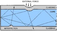
Microbend losses are small microscopic bends of the fibre axis that occur mainly when a fibre is cabled. These bends occur due to external forces, uneven coating applications and improper cabling procedures. Microbends change the path that propagating modes take, as shown in figure.
Macrobend Loss
Macrobend loss are bends having a large radius of curvature relative to the fibre diameter.
Unit - 4
Fibre Optics
Q1) Explain optical fibre as a dielectric wave guide? Also define term Meridional rays and Skew Rays?
A1)
Light propagates inside an optical fibre by virtue of multiple TIRs at the core-cladding interface. The refractive index of the core glass is greater than that of the cladding. This meets the first condition for a TIR. All the light energy that is launched into the optical fibre through its tip does not get guided along the fibre. Only those light rays propagate through the fibre which is launched into the fibre at such an angle that the refracted ray inside the core of the optical fibre is incident on the core-cladding interface at an angle greater than the critical angle of the core with respect to the cladding.
1. Optical fibre is basically a solid glass rod. The diameter of rod is so small that it looks like a fibre.
2. Optical fibre is a dielectric waveguide. The light travels like an electromagnetic wave inside the waveguide. The dielectric waveguide is different from a metallic waveguide which is used at microwave and millimeter wave frequencies.
3. In a metallic waveguide, there is a complete shielding of electromagnetic radiation but in an optical fibre the electromagnetic radiation is not just confined inside the fibre but also extends outside the fibre.
4. The light gets guided inside the structure, through the basic phenomenon of total internal reflection.
5. The optical fibre consists of two concentric cylinders; the inside solid cylinder is called the core and the surrounding shell is called the cladding. (See Fig 12)
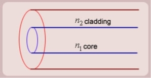
Figure: Schematic of an optical fibre
6. For the light to propagate inside the fibre through total internal reflections at core-cladding interface, the refractive index of the core must be greater than the refractive index of the cladding. That is n1>n2.
SIMPLE RAY MODEL

Figure: (optical fibre with core, cladding and total internally reflected ray)
For propagation of light inside the core there are two possibilities.
1. A light ray is launched in a plane containing the axis of the fibre. We can then see the light ray after total internal reflection travels in the same plane i.e., the ray is confined to the plane in which it was launched and never leave the plane. In this situation the rays will always cross the axis of the fibre. These are called the Meridional rays.
2. The other possibility is that the ray is not launched in a plane containing the axis of the fibre.
For example if the ray is launched at some angle such that it does not intersect the axis of the fibre, then after total internal reflection it will go to some other plane. We can see that in this situation the ray will never intersect the axis of the fibre. The ray essentially will spiral around the axis of fibre. These rays are called the Skew rays.
So it can be concluded that if the light is to propagate inside an optical fibre it could be through two types of rays
a) Meridional rays: The rays which always pass through the axis of fibre giving high optical intensity at the center of the core of the fibre.
b) Skew Rays: The rays which never intersect the axis of the fibre, giving low optical intensity at the center and high intensity towards the rim of the fibre.
Q2) Explain Propagation of Meridional Rays.
A2)
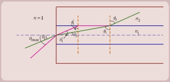
Figure: Propagation of Meridional Rays
1. Let us consider figure. A ray is launched from outside (air) at an angle θ0 , from the axis of the fibre.
The question is, under what conditions the ray is ultimately guided inside the core due to total internal reflections at the core cladding boundary.
2. Let the ray makes an angle θ1 with the axis of the fibre inside the core, and let the ray make an angle ϕ1 with core -cladding interface. Let ϕ2 be the angle of refraction in the cladding.
If ϕ1 < critical angle the ray is refracted in cladding. The ray which goes to cladding is lost and is not useful for communication. The ray which is confined to the core is useful for optical communication.
3. Now as we increase the launching angle θ0, the angle θ1 also increases. Since θ1 + ϕ1 = 
ϕ1 decreases and at some point becomes less than the critical angle. When ϕ1 equals the critical angle, ϕ2 equals  . The maximum launching angle then corresponds to ϕ2 =
  .
.
4. Let us apply Snell’s law at the launching point and at the core-cladding interface for the maximum launching angle θ0max. For this case let θ1 = θ’1 and ϕ1 = ϕ’1
We then have
 (since
  )
)

Now,
So the sine of the maximum angle at which the ray will be guided inside the fibre is given by square root of the difference of squares of the refractive indices of the core and cladding. The quantity sin 0max is called the numerical aperture of an optical fibre. The NA is a measure of the power launching efficiently of an optical fibre.
Q3) Explain total internal reflection.
A3)
The phenomenon which occurs when the light rays travel from a more optically denser medium to a less optically denser medium.
Consider the following situation.
A ray of light passes from a medium of water to that of air. Light ray will be refracted at the junction separating the two media. Since it passes from a medium of a higher refractive index to that having a lower refractive index, the refracted light ray bends away from the normal. At a specific angle of incidence, the incident ray of light is refracted in such a way that it passes along the surface of the water. This particular angle of incidence is called the critical angle. Here the angle of refraction is 90 degrees. When the angle of incidence is greater than the critical angle, the incident ray is reflected back to the medium. We call this phenomenon total internal reflection.

Notations Used in The Total Internal Reflection Formula and Critical Angle
- r is the angle of refraction
- i is the angle of incidence
- n1 is the refractive index in medium 1
- n2 is the refractive index in medium 2
- Ө is the critical angle
Following are the two conditions of total internal reflection:
- The light ray moves from a more denser medium to less dense medium.
- The angle of incidence must be greater than the critical angle.
When the incident ray falls on the cladding, it suffers total internal reflection as the angle formed by the ray is greater than the critical angle. Optical fibres have revolutionised the speed with which signals are transferred, not only across cities but across countries and continents making telecommunication one of the fastest modes of information transfer. Optical fibres are also used in endoscopy.
Q4) What is Numerical aperture?
A4)
Numerical Aperture (NA)
The Numerical Aperture (NA) of a fibre is defined as the sine of the largest angle an incident ray can have for total internal reflectance in the core. Rays launched outside the angle specified by a fibber’s NA will excite radiation modes of the fibre. A higher core index, with respect to the cladding, means larger NA. However, increasing NA causes higher scattering loss from greater concentrations of dopant. A fibre's NA can be determined by measuring the divergence angle of the light cone it emits when all its modes are excited.
Qualitatively, NA is a measure of the light gathering ability of a fibre. It also indicates how easy it is to couple light into a fibre.
Q5) Explain Losses associated with optical fibres.
A5)
Attenuation is the loss of optical power as light travels along the fibre, caused by absorption, scattering, and bending losses. Signal attenuation is defined as the ratio of optical input power (Pi) to the optical output power (Po). The following equation defines signal attenuation as a unit of length:

Factors of Attenuation
Absorption Loss
Absorption is caused by basic fibre-material properties as well as the impurity of transition metals and the presence of (OH-). Absorption in the ultraviolet region is caused by electronic absorption bands. The main cause of Absorption in the infrared region is the characteristic vibration frequency of atomic bonds.
If during fabrication transition metal impurities are introduced in the fibre material, such as iron, nickel, and chromium. Presence of (OH-) also increase absorption of light.
The amount of water (OH-) impurities present in a fibre should be less than a few parts per billion. Fibre attenuation caused by extrinsic absorption is affected by the level of impurities (OH-) present in the fibre. If the amount of impurities in a fibre is reduced, then fibre attenuation is reduced.
Scattering Loss
Scattering losses are caused by the interaction of light with density fluctuations within a fibre. Density changes are produced when optical fibres are manufactured. During manufacturing, regions of higher and lower molecular density areas, relative to the average density of the fibre, are created. Light traveling through the fibre interacts with the density areas and light is then partially scattered in all directions.
According to Rayleigh scattering loss is inversely proportional to the fourth power of the wavelength i.e., 1 / l4.
Microbend Loss
Microbend losses are small microscopic bends of the fibre axis that occur mainly when a fibre is cabled. These bends occur due to external forces, uneven coating applications and improper cabling procedures. Microbends change the path that propagating modes take, as shown in figure.
Macrobend Loss
Macrobend loss are bends having a large radius of curvature relative to the fibre diameter.
Mode Coupling Loss
Coupling loss in fibre optics refers to the power loss that occurs when coupling light from one optical device or medium to another
Q6) Explain Step and graded index fibres
A6)
The types of optical fibres depend on the refractive index, materials used, and mode of propagation of light.
The classification based on the materials used is as follows:
- Plastic Optical Fibres: The polymethylmethacrylate is used as a core material for the transmission of light.
Example:
Core: polymethyl methacrylate : Cladding: Co- Polymer
Core: Polystyrene : Cladding: Methyl methacrylate
- Glass Fibres: It consists of extremely fine glass fibres.
Example:
Core: SiO2 Cladding: SiO2
Core: GeO2- SiO2 Cladding: SiO2
The classification based on the mode of propagation of light is as follows:
Mode of propagation:
Light propagates as electromagnetic waves through an optical fibre. All waves, having ray directions above the critical angle will be trapped within the fibre due to total internal reflection. However, all such waves do not propagate through the fibre. Only certain ray directions are allowed to propagate. The allowed directions correspond to the modes of the fibre. In simple terms, modes can be visualized as the possible number of paths of light in an optical fibre.
- Single-Mode Fibres:
These fibres are used for long-distance transmission of signals. In general, the single-mode fibres are step-index fibres. These types of fibres are made from doped silica. It has a very small core diameter so that it can allow only one mode of propagation and hence called single-mode fibres.
The cladding diameter must be very large compared to the core diameter. Thus in the case of single-mode fibre, the optical loss is very much reduced. The structure of a single-mode fibre is given below.
Structure:
Core diameter: 5-10μm
Cladding diameter: Generally around 125μm
Protective layer: 250 to 1000μm
Numerical aperture: 0.08 to 0.10
Bandwidth: More than 50MHz km.
Application:
Because of high bandwidth, they are used in long-haul communication systems.
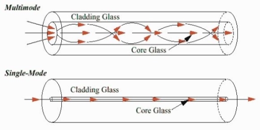
Figure: Single Mode and Multimode Fibre
- Multimode Fibres:
These fibres are used for short-distance transmission of signals. The multi-mode fibres are useful in manufacturing both for step-index and graded-index fibres. The multi-mode fibres are made by multi-component glass compounds such as Glass – Clad Glass, Silica – Clad – Silica, doped silica, etc. Here the core diameter is very large compared to single-mode fibres, so that it can allow many modes to propagate through it and hence called Multi-mode fibres. The cladding diameter is also larger than the diameter of the single-mode fibres. The structure of the multimode fibre is as shown in the figure above.
Structure:
Core diameter : 50-350μm
Cladding diameter : 125μm - 500μm
Protective layer : 250 to 1100μm
Numerical aperture : 0.12 to 0.5
Bandwidth : Less than 50MHz km.
The total number of modes possible for such an electromagnetic waveguide is

Here
d = core diameter
NA = numerical aperture
 = Optical wavelength
Application:
Because of its less bandwidth, it is very useful in short-haul communication systems.
The classification based on the refractive index is as follows:
- Step Index Single-mode Fibres
It consists of a core surrounded by the cladding, which has a single uniform index of refraction. Step index-single mode fibres: A single-mode step-index fibre consists of a very thin core of uniform refractive index surrounded by a cladding of refractive index lower than that of the core. The refractive index abruptly changes at the core-cladding boundary. Light travels along a side path, i.e., along the axis only. So zero-order modes are supported by Single Mode Fibre.
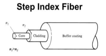
Figure: Step Index Single-mode Fibres
- Step index-Multimode fibres
A multimode step-index fibre consists of a core of uniform refractive index surrounded by a cladding of refractive index lower than that of the core. The refractive index abruptly changes at the core-cladding boundary. The core is of large diameter. Light follows zigzag paths inside the fibre. Many such zigzag paths of propagation are permitted in Multi-Mode Fibre. The Numerical Aperture of a Multi-mode fibre is larger as the core diameter of the fibre is larger
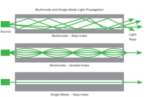
Figure: Step index-Multimode fibres
- Graded Index Fibres:
The refractive index of the optical fibre decreases as the radial distance from the fibre axis increases. GRIN fibre is one in which the refractive index varies radially, decreasing continuously in a parabolic manner from the maximum value of n1, at the center of the core to a constant value of n2 at the core-cladding interface.
In graded-index fibre, light rays travel at different speeds in different parts of the fibre because the refractive index varies throughout the fibre. Near the outer edge, the refractive index is lower. As a result, rays near the outer edge travel faster than the rays at the center of the core. Because of this, rays arrive at the end of the fibre at approximately the same time. In effect light rays that arrive at the end of the fibre are continuously refocused as they travel down the fibre. All rays take the same amount of time in traversing the fibre. This leads to small pulse dispersion.
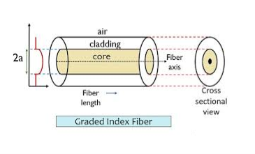
Figure: Graded Index Fibres
The pulse dispersion is given by

Here

For a parabolic index fibre, the pulse dispersion is reduced by a factor of about 200 in comparison to step-index fibre. It is because of this reason that first and second-generation optical communication systems used near parabolic index fibres.
Q7) Write some application of optical fibres.
A7)
- Medical
Used as light guides, imaging tools and also as lasers for surgeries
- Defence/Government
Used as hydrophones for seismic waves and SONAR, as wiring in aircraft, submarines and other vehicles and also for field networking
- Data Storage
Used for data transmission
- Telecommunications
Fibre is laid and used for transmitting and receiving purposes
- Networking
Used to connect users and servers in a variety of network settings and help increase the speed and accuracy of data transmission
- Industrial/Commercial
Used for imaging in hard to reach areas, as wiring where EMI is an issue, as sensory devices to make temperature, pressure and other measurements, and as wiring in automobiles and in industrial settings
- Broadcast/CATV
Broadcast/cable companies are using fibre optic cables for wiring CATV, HDTV, internet, video on-demand and other applications
Fibre optic cables are used for lighting and imaging and as sensors to measure and monitor a vast array of variables. Fibre optic cables are also used in research and development and testing across all the above-mentioned industries.
Q8) Explain “V Number”.
A8)
“V Number”
The Normalized Frequency Parameter of a fibre, also called the V number, is a useful specification. Many fibre parameters can be expressed in terms of V, such as: the number of modes at a given wavelength, mode cut off conditions, and propagation constants. For example, the number of guided modes in a step index multimode fibre is given by V2/2, and a step index fibre becomes single-mode for a given wavelength when V<2.405. Mathematically, V=2 π·NA·a/λ where “a” is the fibre core radius.
V – number determines how many modes a fibre can support, it is given by,

Where d is the diameter of the core, l is the wavelength of light used and NA is the numerical aperture of the fibre.

Or

If V ≤ 2.405, then the fibre is single mode fibre (SMF)
If V > 2.405, then the fibre is multimode fibre (MMF)
Number of Modes traveling in Fibre
The total number of modes traveling in a fibre depends on the V – Number and is related as:
For Step Index Fibre:

For Graded Index Fibre: 
Q9) Explain graded index fibre.
A9)
The refractive index of the optical fibre decreases as the radial distance from the fibre axis increases. GRIN fibre is one in which the refractive index varies radially, decreasing continuously in a parabolic manner from the maximum value of n1, at the center of the core to a constant value of n2 at the core-cladding interface.
In graded-index fibre, light rays travel at different speeds in different parts of the fibre because the refractive index varies throughout the fibre. Near the outer edge, the refractive index is lower. As a result, rays near the outer edge travel faster than the rays at the center of the core. Because of this, rays arrive at the end of the fibre at approximately the same time. In effect light rays that arrive at the end of the fibre are continuously refocused as they travel down the fibre. All rays take the same amount of time in traversing the fibre. This leads to small pulse dispersion.
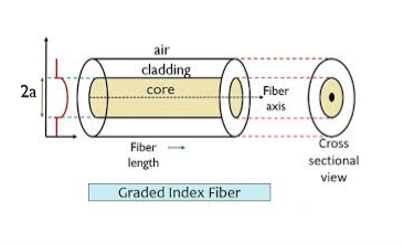
Figure: Graded Index Fibres
The pulse dispersion is given by

Here

For a parabolic index fibre, the pulse dispersion is reduced by a factor of about 200 in comparison to step-index fibre. It is because of this reason that first and second-generation optical communication systems used near parabolic index fibres.
Q10) Write short note on microbend and macrobend loss.
A10)
Microbend Loss
Microbend losses are small microscopic bends of the fibre axis that occur mainly when a fibre is cabled. These bends occur due to external forces, uneven coating applications and improper cabling procedures. Microbends change the path that propagating modes take, as shown in figure.
Macrobend Loss
Macrobend loss are bends having a large radius of curvature relative to the fibre diameter.
Unit - 4
Fibre Optics
Q1) Explain optical fibre as a dielectric wave guide? Also define term Meridional rays and Skew Rays?
A1)
Light propagates inside an optical fibre by virtue of multiple TIRs at the core-cladding interface. The refractive index of the core glass is greater than that of the cladding. This meets the first condition for a TIR. All the light energy that is launched into the optical fibre through its tip does not get guided along the fibre. Only those light rays propagate through the fibre which is launched into the fibre at such an angle that the refracted ray inside the core of the optical fibre is incident on the core-cladding interface at an angle greater than the critical angle of the core with respect to the cladding.
1. Optical fibre is basically a solid glass rod. The diameter of rod is so small that it looks like a fibre.
2. Optical fibre is a dielectric waveguide. The light travels like an electromagnetic wave inside the waveguide. The dielectric waveguide is different from a metallic waveguide which is used at microwave and millimeter wave frequencies.
3. In a metallic waveguide, there is a complete shielding of electromagnetic radiation but in an optical fibre the electromagnetic radiation is not just confined inside the fibre but also extends outside the fibre.
4. The light gets guided inside the structure, through the basic phenomenon of total internal reflection.
5. The optical fibre consists of two concentric cylinders; the inside solid cylinder is called the core and the surrounding shell is called the cladding. (See Fig 12)
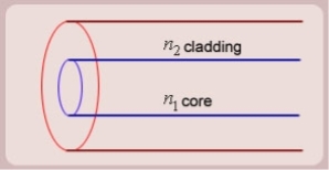
Figure: Schematic of an optical fibre
6. For the light to propagate inside the fibre through total internal reflections at core-cladding interface, the refractive index of the core must be greater than the refractive index of the cladding. That is n1>n2.
SIMPLE RAY MODEL

Figure: (optical fibre with core, cladding and total internally reflected ray)
For propagation of light inside the core there are two possibilities.
1. A light ray is launched in a plane containing the axis of the fibre. We can then see the light ray after total internal reflection travels in the same plane i.e., the ray is confined to the plane in which it was launched and never leave the plane. In this situation the rays will always cross the axis of the fibre. These are called the Meridional rays.
2. The other possibility is that the ray is not launched in a plane containing the axis of the fibre.
For example if the ray is launched at some angle such that it does not intersect the axis of the fibre, then after total internal reflection it will go to some other plane. We can see that in this situation the ray will never intersect the axis of the fibre. The ray essentially will spiral around the axis of fibre. These rays are called the Skew rays.
So it can be concluded that if the light is to propagate inside an optical fibre it could be through two types of rays
a) Meridional rays: The rays which always pass through the axis of fibre giving high optical intensity at the center of the core of the fibre.
b) Skew Rays: The rays which never intersect the axis of the fibre, giving low optical intensity at the center and high intensity towards the rim of the fibre.
Q2) Explain Propagation of Meridional Rays.
A2)
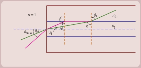
Figure: Propagation of Meridional Rays
1. Let us consider figure. A ray is launched from outside (air) at an angle θ0 , from the axis of the fibre.
The question is, under what conditions the ray is ultimately guided inside the core due to total internal reflections at the core cladding boundary.
2. Let the ray makes an angle θ1 with the axis of the fibre inside the core, and let the ray make an angle ϕ1 with core -cladding interface. Let ϕ2 be the angle of refraction in the cladding.
If ϕ1 < critical angle the ray is refracted in cladding. The ray which goes to cladding is lost and is not useful for communication. The ray which is confined to the core is useful for optical communication.
3. Now as we increase the launching angle θ0, the angle θ1 also increases. Since θ1 + ϕ1 = 
ϕ1 decreases and at some point becomes less than the critical angle. When ϕ1 equals the critical angle, ϕ2 equals  . The maximum launching angle then corresponds to ϕ2 =
  .
.
4. Let us apply Snell’s law at the launching point and at the core-cladding interface for the maximum launching angle θ0max. For this case let θ1 = θ’1 and ϕ1 = ϕ’1
We then have
 (since
  )
)

Now,
So the sine of the maximum angle at which the ray will be guided inside the fibre is given by square root of the difference of squares of the refractive indices of the core and cladding. The quantity sin 0max is called the numerical aperture of an optical fibre. The NA is a measure of the power launching efficiently of an optical fibre.
Q3) Explain total internal reflection.
A3)
The phenomenon which occurs when the light rays travel from a more optically denser medium to a less optically denser medium.
Consider the following situation.
A ray of light passes from a medium of water to that of air. Light ray will be refracted at the junction separating the two media. Since it passes from a medium of a higher refractive index to that having a lower refractive index, the refracted light ray bends away from the normal. At a specific angle of incidence, the incident ray of light is refracted in such a way that it passes along the surface of the water. This particular angle of incidence is called the critical angle. Here the angle of refraction is 90 degrees. When the angle of incidence is greater than the critical angle, the incident ray is reflected back to the medium. We call this phenomenon total internal reflection.
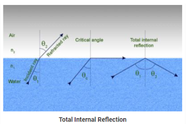

Notations Used in The Total Internal Reflection Formula and Critical Angle
- r is the angle of refraction
- i is the angle of incidence
- n1 is the refractive index in medium 1
- n2 is the refractive index in medium 2
- Ө is the critical angle
Following are the two conditions of total internal reflection:
- The light ray moves from a more denser medium to less dense medium.
- The angle of incidence must be greater than the critical angle.
When the incident ray falls on the cladding, it suffers total internal reflection as the angle formed by the ray is greater than the critical angle. Optical fibres have revolutionised the speed with which signals are transferred, not only across cities but across countries and continents making telecommunication one of the fastest modes of information transfer. Optical fibres are also used in endoscopy.
Q4) What is Numerical aperture?
A4)
Numerical Aperture (NA)
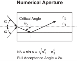
The Numerical Aperture (NA) of a fibre is defined as the sine of the largest angle an incident ray can have for total internal reflectance in the core. Rays launched outside the angle specified by a fibber’s NA will excite radiation modes of the fibre. A higher core index, with respect to the cladding, means larger NA. However, increasing NA causes higher scattering loss from greater concentrations of dopant. A fibre's NA can be determined by measuring the divergence angle of the light cone it emits when all its modes are excited.
Qualitatively, NA is a measure of the light gathering ability of a fibre. It also indicates how easy it is to couple light into a fibre.
Q5) Explain Losses associated with optical fibres.
A5)
Attenuation is the loss of optical power as light travels along the fibre, caused by absorption, scattering, and bending losses. Signal attenuation is defined as the ratio of optical input power (Pi) to the optical output power (Po). The following equation defines signal attenuation as a unit of length:

Factors of Attenuation
Absorption Loss
Absorption is caused by basic fibre-material properties as well as the impurity of transition metals and the presence of (OH-). Absorption in the ultraviolet region is caused by electronic absorption bands. The main cause of Absorption in the infrared region is the characteristic vibration frequency of atomic bonds.
If during fabrication transition metal impurities are introduced in the fibre material, such as iron, nickel, and chromium. Presence of (OH-) also increase absorption of light.
The amount of water (OH-) impurities present in a fibre should be less than a few parts per billion. Fibre attenuation caused by extrinsic absorption is affected by the level of impurities (OH-) present in the fibre. If the amount of impurities in a fibre is reduced, then fibre attenuation is reduced.
Scattering Loss
Scattering losses are caused by the interaction of light with density fluctuations within a fibre. Density changes are produced when optical fibres are manufactured. During manufacturing, regions of higher and lower molecular density areas, relative to the average density of the fibre, are created. Light traveling through the fibre interacts with the density areas and light is then partially scattered in all directions.
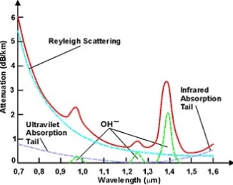
According to Rayleigh scattering loss is inversely proportional to the fourth power of the wavelength i.e., 1 / l4.
Microbend Loss
Microbend losses are small microscopic bends of the fibre axis that occur mainly when a fibre is cabled. These bends occur due to external forces, uneven coating applications and improper cabling procedures. Microbends change the path that propagating modes take, as shown in figure.
Macrobend Loss
Macrobend loss are bends having a large radius of curvature relative to the fibre diameter.
Mode Coupling Loss
Coupling loss in fibre optics refers to the power loss that occurs when coupling light from one optical device or medium to another
Q6) Explain Step and graded index fibres
A6)
The types of optical fibres depend on the refractive index, materials used, and mode of propagation of light.
The classification based on the materials used is as follows:
- Plastic Optical Fibres: The polymethylmethacrylate is used as a core material for the transmission of light.
Example:
Core: polymethyl methacrylate : Cladding: Co- Polymer
Core: Polystyrene : Cladding: Methyl methacrylate
- Glass Fibres: It consists of extremely fine glass fibres.
Example:
Core: SiO2 Cladding: SiO2
Core: GeO2- SiO2 Cladding: SiO2
The classification based on the mode of propagation of light is as follows:
Mode of propagation:
Light propagates as electromagnetic waves through an optical fibre. All waves, having ray directions above the critical angle will be trapped within the fibre due to total internal reflection. However, all such waves do not propagate through the fibre. Only certain ray directions are allowed to propagate. The allowed directions correspond to the modes of the fibre. In simple terms, modes can be visualized as the possible number of paths of light in an optical fibre.
- Single-Mode Fibres:
These fibres are used for long-distance transmission of signals. In general, the single-mode fibres are step-index fibres. These types of fibres are made from doped silica. It has a very small core diameter so that it can allow only one mode of propagation and hence called single-mode fibres.
The cladding diameter must be very large compared to the core diameter. Thus in the case of single-mode fibre, the optical loss is very much reduced. The structure of a single-mode fibre is given below.
Structure:
Core diameter: 5-10μm
Cladding diameter: Generally around 125μm
Protective layer: 250 to 1000μm
Numerical aperture: 0.08 to 0.10
Bandwidth: More than 50MHz km.
Application:
Because of high bandwidth, they are used in long-haul communication systems.
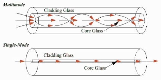
Figure: Single Mode and Multimode Fibre
- Multimode Fibres:
These fibres are used for short-distance transmission of signals. The multi-mode fibres are useful in manufacturing both for step-index and graded-index fibres. The multi-mode fibres are made by multi-component glass compounds such as Glass – Clad Glass, Silica – Clad – Silica, doped silica, etc. Here the core diameter is very large compared to single-mode fibres, so that it can allow many modes to propagate through it and hence called Multi-mode fibres. The cladding diameter is also larger than the diameter of the single-mode fibres. The structure of the multimode fibre is as shown in the figure above.
Structure:
Core diameter : 50-350μm
Cladding diameter : 125μm - 500μm
Protective layer : 250 to 1100μm
Numerical aperture : 0.12 to 0.5
Bandwidth : Less than 50MHz km.
The total number of modes possible for such an electromagnetic waveguide is

Here
d = core diameter
NA = numerical aperture
 = Optical wavelength
Application:
Because of its less bandwidth, it is very useful in short-haul communication systems.
The classification based on the refractive index is as follows:
- Step Index Single-mode Fibres
It consists of a core surrounded by the cladding, which has a single uniform index of refraction. Step index-single mode fibres: A single-mode step-index fibre consists of a very thin core of uniform refractive index surrounded by a cladding of refractive index lower than that of the core. The refractive index abruptly changes at the core-cladding boundary. Light travels along a side path, i.e., along the axis only. So zero-order modes are supported by Single Mode Fibre.
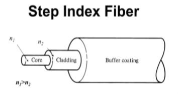
Figure: Step Index Single-mode Fibres
- Step index-Multimode fibres
A multimode step-index fibre consists of a core of uniform refractive index surrounded by a cladding of refractive index lower than that of the core. The refractive index abruptly changes at the core-cladding boundary. The core is of large diameter. Light follows zigzag paths inside the fibre. Many such zigzag paths of propagation are permitted in Multi-Mode Fibre. The Numerical Aperture of a Multi-mode fibre is larger as the core diameter of the fibre is larger
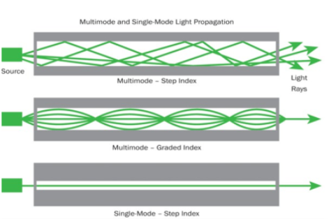
Figure: Step index-Multimode fibres
- Graded Index Fibres:
The refractive index of the optical fibre decreases as the radial distance from the fibre axis increases. GRIN fibre is one in which the refractive index varies radially, decreasing continuously in a parabolic manner from the maximum value of n1, at the center of the core to a constant value of n2 at the core-cladding interface.
In graded-index fibre, light rays travel at different speeds in different parts of the fibre because the refractive index varies throughout the fibre. Near the outer edge, the refractive index is lower. As a result, rays near the outer edge travel faster than the rays at the center of the core. Because of this, rays arrive at the end of the fibre at approximately the same time. In effect light rays that arrive at the end of the fibre are continuously refocused as they travel down the fibre. All rays take the same amount of time in traversing the fibre. This leads to small pulse dispersion.
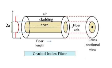
Figure: Graded Index Fibres
The pulse dispersion is given by

Here

For a parabolic index fibre, the pulse dispersion is reduced by a factor of about 200 in comparison to step-index fibre. It is because of this reason that first and second-generation optical communication systems used near parabolic index fibres.
Q7) Write some application of optical fibres.
A7)
- Medical
Used as light guides, imaging tools and also as lasers for surgeries
- Defence/Government
Used as hydrophones for seismic waves and SONAR, as wiring in aircraft, submarines and other vehicles and also for field networking
- Data Storage
Used for data transmission
- Telecommunications
Fibre is laid and used for transmitting and receiving purposes
- Networking
Used to connect users and servers in a variety of network settings and help increase the speed and accuracy of data transmission
- Industrial/Commercial
Used for imaging in hard to reach areas, as wiring where EMI is an issue, as sensory devices to make temperature, pressure and other measurements, and as wiring in automobiles and in industrial settings
- Broadcast/CATV
Broadcast/cable companies are using fibre optic cables for wiring CATV, HDTV, internet, video on-demand and other applications
Fibre optic cables are used for lighting and imaging and as sensors to measure and monitor a vast array of variables. Fibre optic cables are also used in research and development and testing across all the above-mentioned industries.
Q8) Explain “V Number”.
A8)
“V Number”
The Normalized Frequency Parameter of a fibre, also called the V number, is a useful specification. Many fibre parameters can be expressed in terms of V, such as: the number of modes at a given wavelength, mode cut off conditions, and propagation constants. For example, the number of guided modes in a step index multimode fibre is given by V2/2, and a step index fibre becomes single-mode for a given wavelength when V<2.405. Mathematically, V=2 π·NA·a/λ where “a” is the fibre core radius.
V – number determines how many modes a fibre can support, it is given by,

Where d is the diameter of the core, l is the wavelength of light used and NA is the numerical aperture of the fibre.

Or

If V ≤ 2.405, then the fibre is single mode fibre (SMF)
If V > 2.405, then the fibre is multimode fibre (MMF)
Number of Modes traveling in Fibre
The total number of modes traveling in a fibre depends on the V – Number and is related as:
For Step Index Fibre:

For Graded Index Fibre: 
Q9) Explain graded index fibre.
A9)
The refractive index of the optical fibre decreases as the radial distance from the fibre axis increases. GRIN fibre is one in which the refractive index varies radially, decreasing continuously in a parabolic manner from the maximum value of n1, at the center of the core to a constant value of n2 at the core-cladding interface.
In graded-index fibre, light rays travel at different speeds in different parts of the fibre because the refractive index varies throughout the fibre. Near the outer edge, the refractive index is lower. As a result, rays near the outer edge travel faster than the rays at the center of the core. Because of this, rays arrive at the end of the fibre at approximately the same time. In effect light rays that arrive at the end of the fibre are continuously refocused as they travel down the fibre. All rays take the same amount of time in traversing the fibre. This leads to small pulse dispersion.
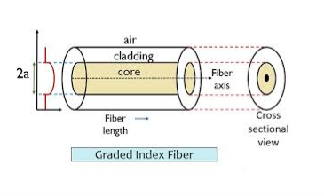
Figure: Graded Index Fibres
The pulse dispersion is given by

Here

For a parabolic index fibre, the pulse dispersion is reduced by a factor of about 200 in comparison to step-index fibre. It is because of this reason that first and second-generation optical communication systems used near parabolic index fibres.
Q10) Write short note on microbend and macrobend loss.
A10)
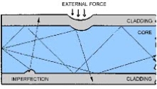
Microbend Loss
Microbend losses are small microscopic bends of the fibre axis that occur mainly when a fibre is cabled. These bends occur due to external forces, uneven coating applications and improper cabling procedures. Microbends change the path that propagating modes take, as shown in figure.
Macrobend Loss
Macrobend loss are bends having a large radius of curvature relative to the fibre diameter.
