Unit - 2
Strength Behavior of Rocks
Q1) Explain what do you mean by stress?
A1) Stress
Plate collisions and the accumulated weight of overlying rocks exert forces on rocks at depth. While the size of the force is important, it also matters whether the force is distributed over a wide region, or tightly focused on a small area. The same force will have a greater effect when acting over a small area than when acting over a larger area. If you have ever used snowshoes to walk across a snowbank without sinking in, you have taken advantage of the effects of distributing force (your mass acted upon by gravity) over a wider area (the area of your snowshoes rather than the soles of your boots). Stress is force adjusted for the area over which it is distributed. The strain is the change in shape that happens when rocks are deformed by stress.
Types of Stress
Stresses fall into two categories: normal stress acts at right angles to a surface, and shear stress acts parallel to a surface. Normal stress is subdivided into compression when the stresses are squeezing a rock, and tension when stress is pulling it apart. Rocks undergo compression in regions where plates are colliding, or where they are being buried beneath other rocks. Rocks experience tension where divergence is happening, such as when a continent is beginning the rifting process. Shear stress is characteristic of transform plate boundaries, where plates are moving side by side.
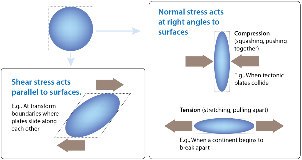
Fig. Rocks can be affected by normal stress (compression and tension) or shear stress.
Although Fig shows only one set of stress arrows for each scenario, rocks within the Earth are subject to stress from all directions. The relative size of the stresses in different directions will determine the response of the rock. Consider a deeply buried rock being stretched as a continent breaks apart (Fig 4.2). It is also being compressed by the weight of overlying sediments and rocks, but the stress from compression is relatively small compared to the tension from rifting. The net effect of stress acting on the rock will be determined more by the tension from rifting than by the compression from overlying rocks.
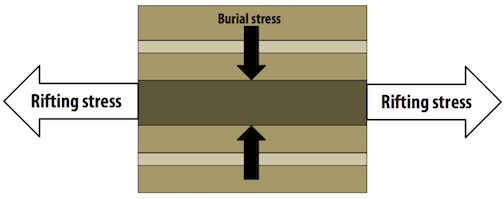
Fig. A rock layer (dark brown) is compressed by the weight of rocks above and stretched by rifting.
Rocks experience stress from all directions, but it is possible to break down stresses into three directions, just like a graph with x, y, and z axes. In diagrams showing these three directions, the sizes of arrows representing each direction will indicate the relative size of stresses, as they do in Fig 4.2. Analyzing stress in this way makes it much easier to describe the stresses operating on a rock, and to understand what their net effect will be.
Q2) Explain types of strain and what do you mean by ductile and brittle material in detail.
A2) Types of Strain
How a rock responds to stress depends on many factors. The “how” is not simply a matter of how much strain a rock will undergo, but what type of strain will occur.
Elastic Strain
Elastic strain is a reversible strain. You can think of elastic strain as what happens to the elastic waistband of your favorite sweatpants when you put them on. The elastic stretches to let you into your pants, and once you’re in them, it shrinks to keep them from falling. When you take the pants off again, the elastic goes back to its original shape. Similarly, rocks undergoing elastic strain will snap back to their original shape once the stress is removed. Rocks snapping back to their original shape undergo elastic rebound. The elastic rebound of rocks on a large scale can have profound consequences because the energy released causes the Earth to vibrate. We experience those vibrations as earthquakes.
Plastic Strain
If enough stress is applied, the changes that a material undergoes to accommodate the stress will leave it permanently deformed. When the stress is removed, the material does not go back to its original shape. The permanent deformation is called plastic strain.
Ductile or Brittle
Ductile deformation refers to deformation that happens by flowing or stretching. The marble monument in Fig is undergoing ductile deformation as it sags beneath its weight.
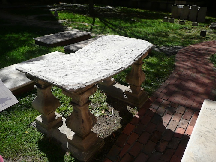 Fig. The horizontal surface is undergoing slow ductile deformation as it sags beneath its weight.
When a material breaks, it has undergone brittle deformation. The stone cylinders in Fig are part of an experiment to test the strength of the rock. The cylinder on the right looked like the cylinder on the left before it was compressed, with force applied to the top and bottom. Strain gauges have been glued on to measure the amount of deformation lengthwise and across the cylinders.
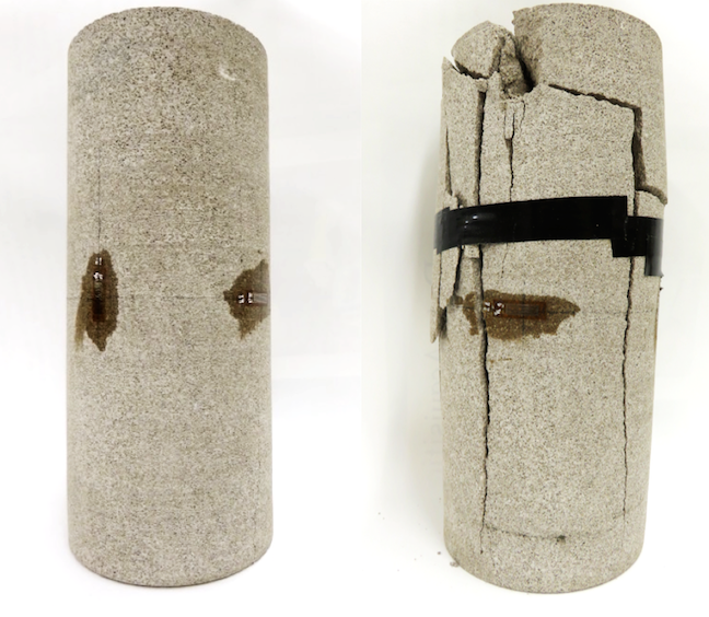
Fig. Cylinders of rock used to test the strength of rock under compression
A material can undergo more than one kind of deformation when stress is applied. The barrel-shaped cylinder of potash in Fig 4.5 (right) originally looked like the cylinder on the left. The cylinder was compressed, with stress applied from the top and bottom. Initially, it underwent ductile deformation and thickened in the middle, creating the barrel shape. But as more stress was applied, the cylinder eventually underwent brittle deformation, resulting in the crack across the middle.
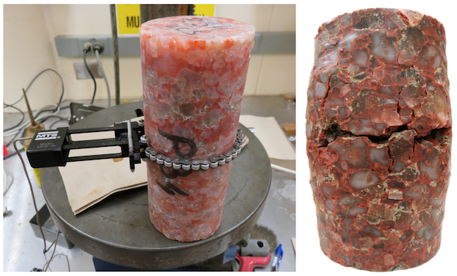
Fig. Cylinders of potash before and after deformation
Q3) Explain factors that determine how a rock will deform, composition of rock, temperature and pressure.
A3) Factors That Determine How a Rock Will Deform
A rock is not limited to exclusively brittle deformation or exclusively ductile deformation. Even the deformed rock in Fig 4.4, which has undergone brittle deformation, shows a slight curvature on the right side, near the top. This indicates that a small amount of ductile deformation occurred before brittle failure.
For a given rock, deformation will be different depending on the amount of stress applied. Up to a point, rocks undergo elastic deformation and will spring back to their original shape after the stress is removed. If more stress is applied, the rock may deform in a ductile manner. If stress increases further, the rock may fracture. The amount of stress required in each case will depend on the type of rock, as well as conditions such as pressure and temperature.
Composition
In general, sedimentary rocks will be more likely to undergo ductile deformation than igneous or metamorphic rocks under the same conditions. Rocks within each group will also deform differently.
Boudinage structures (Fig.) highlight the effect of composition on how rocks deform. These structures occur when a stronger rock more prone to brittle deformation is surrounded by weaker rocks prone to ductile deformation. The stronger rock will fracture into segments, called boudins, and the weaker rock will flow into the spaces between. In Fig 4.6(top), the white layer reached the stage of pinching off, just before separating into segments. The surrounding black layer flowed in to fill the gap where the pinch was happening. Remarkably, the white layer itself contains a dark layer that has fragmented into boudins. Not all boudins break into blocky segments. Some display more ductile deformation (Fig 4.6, bottom).
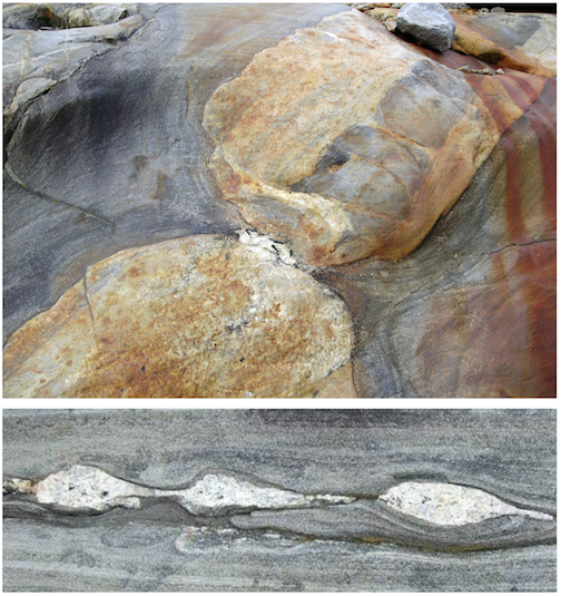
Fig. Two examples of boudinage structure.
Temperature and Pressure
At higher temperatures, and under higher confining pressures, rocks are more likely to undergo ductile deformation. Confining pressure is the stress that a material experiences uniformly from all sides as a result of the weight of material above and around it. The pressure that a diver feels deep in the ocean is confining pressure due to the weight of water above and around the diver. This kind of confining pressure is called hydrostatic pressure. Within Earth, the confining pressure is due to the weight of overlying rocks. Confining pressure due to the weight of rocks is called lithostatic pressure.
The rocks in Fig 4.4 and 4.5 experienced confining pressure from the atmosphere, and temperatures comfortable for the humans working in the lab. Under those conditions, the rocks ultimately underwent brittle failure when they were compressed in the lab. Deep within the crust, the temperatures and confining pressures are far greater. Deep enough within the crust, both samples would undergo only ductile deformation if the same amount of stress were applied as in the experiment. The depth at which temperatures and confining pressures are high enough for rocks to go from brittle deformation to ductile deformation is called the brittle-ductile transition zone.
The brittle-ductile transition zone occurs between approximately 10 km and 30 km depth, corresponding to temperatures around 300 ºC and greater. The depth at which temperatures reach 300 ºC at any particular location will depend on heat flow at that location. In the continental crust, rocks at 300 ºC are deeper than in the ocean crust. The change in pressure with depth also varies, depending on the mass and density of rocks. If depths are measured relative to sea level, the pressure at 10 km measured beneath a tall mountain belt will be greater than the pressure at 10 km measured within ocean crust.
Experiments like those shown in Fig 4.4 and 4.5 can be used to determine where the brittle-ductile transition zone will be for a particular rock type. Experimenters apply stress to a sample of a rock for a range of temperatures and confining pressures. They note the conditions under which the rock breaks or deforms in a ductile manner, and plot those on a graph (Fig 4.7). The results in Fig 4.7 are from experiments on limestone. The vertical axis is pressure. The more pressure, the deeper the rock would have to be within the Earth to experience that pressure. The white line represents the brittle-ductile transition zone. Above the white line are pressures and temperatures under which the limestone would fracture. Below the white line in the tan area is pressures and temperatures where the limestone would deform by flowing. Notice that the higher the temperatures, the less confining pressure is required for ductile deformation.
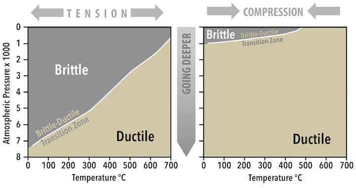 Fig. Experimental results on limestone with tension applied (left) and compression applied (right).
Q4) What do you mean by geological structure, fluids and deformation?
A4) Fluids
When rocks are under pressure, fluids trapped within the pore spaces of rocks- the gaps between grains- are also under pressure. Higher confining pressure is required for deformation to be ductile rather than brittle, but pressure from fluids, called pore pressure, resists the confining pressure. The result is that the effective confining pressure is lower than it would be without the fluids. Depending on the amount of pore pressure, and how close the rock is to the brittle-ductile transition zone, pore pressure could cause brittle failure in a rock that would otherwise undergo ductile deformation.
Stress and Geological Structures
Many different geologic structures can form when stress is applied to rocks. Structures form as a result of fracturing, tilting, folding, stretching, and squeezing (Fig 4.8). Some structures, like the fractures that make basalt columns (Fig 4.8, upper left), happen when rocks shrink due to cooling, but others are a consequence of plate tectonic forces. The types of structures that form depend on the plate tectonic setting and other geological conditions, making them valuable tools for understanding what happened to the rocks. The following sections address the different kinds of structures that form, and what information we can gather from these structures to learn more about the tectonic environment and regional geology.
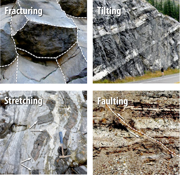
Fig. Structures resulting from deformation.
Deformation
When rocks deform they are said to strain. A strain is a change in the size, shape, or volume of a material. We here modify that definition somewhat to say that a strain also includes any kind of movement of the material, including translation and tilting.
Stages of Deformation
When a rock is subjected to increasing stress it passes through 3 successive stages of deformation.
• Elastic Deformation -- wherein the strain is reversible.
• Ductile Deformation -- wherein the strain is irreversible.
• Fracture - irreversible strain wherein the material breaks.
We can divide materials into two classes that depend on their relative behavior under stress.
- Brittle materials have a small or large region of elastic behavior but only a small region of ductile behavior before they fracture.
- Ductile materials have a small region of elastic behavior and a large region of ductile behavior before they fracture.
How a material behaves will depend on several factors. Among them are:
- Temperature - At high-temperature molecules and their bonds can stretch and move, thus materials will behave in a more ductile manner. At low Temperatures, materials are brittle.
- Confining Pressure - At high confining pressure materials are less likely to fracture because the pressure of the surroundings tends to hinder the formation of fractures. At low confining stress, the material will be brittle and tend to fracture sooner.
- Strain rate -- At high strain rates material tends to fracture. At low strain rates, more time is available for individual atoms to move, and therefore ductile behavior is favored.
- Composition -- Some minerals, like quartz, olivine, and feldspars are very brittle. Others, like clay minerals, micas, and calcite are more ductile This is due to the chemical bond types that hold them together. Thus, the mineralogical composition of the rock will be a factor in determining the deformational behavior of the rock. Another aspect is the presence or absence of water. Water appears to weaken the chemical bonds and forms films around mineral grains along which slippage can take place. Thus wet rock tends to behave in a ductile manner, while dry rocks tend to behave in a brittle manner.
Q5) Explain what is dip and strike and brittle and ductile properties of lithosphere?
A5) Brittle-Ductile Properties of the Lithosphere
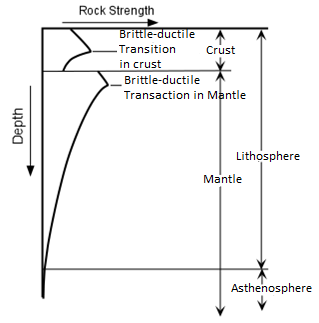
We all know that rocks near the surface of the Earth behave in a brittle manner. Crustal rocks are composed of minerals like quartz and feldspar which have high strength, particularly at low pressure and temperature. As we go deeper into the Earth the strength of these rocks initially increases.
At a depth of about 15 km, we reach a point called the brittle-ductile transition zone. Below this point rock strength decreases because fractures become closed and the temperature is higher, making the rocks behave in a ductile manner. At the base of the crust the rock type changes to peridotite which is rich in olivine. Olivine is stronger than the minerals that make up most crustal rocks, so the upper part of the mantle is again strong. But, just as in the crust, increasing temperature eventually predominates and at a depth of about 40 km, the brittle-ductile transition zone in the mantle occurs. Below this point, rocks behave in an increasingly ductile manner.
Deformation in Progress
Only in a few cases does deformation of rocks occur at a rate that is observable on human time scales. Abrupt deformation along faults, usually associated with earthquakes occurs on a time scale of minutes or seconds. Gradual deformation along faults or in areas of uplift or subsidence can be measured over periods of months to years with sensitive measuring instruments.
Evidence of Past Deformation
Evidence of deformation that has occurred in the past is very evident in crustal rocks. For example, sedimentary strata and lava flow generally follow the law of original horizontality. Thus, when we see such strata inclined instead of horizontal, evidence of an episode of deformation.
Dip and Strike
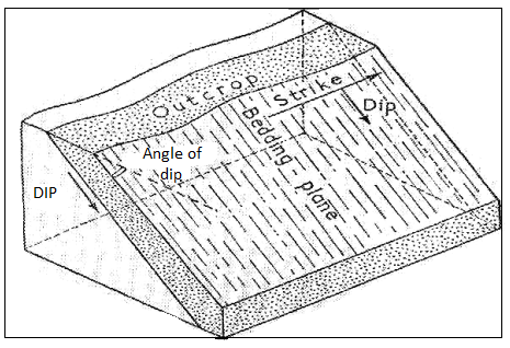
The dip is essentially an angle of inclination of the bed. It is defined as the amount of inclination of a bed for a horizontal plane. This is measured on a vertical plane lying at right angles to the strike of the bedding.
The dip of a bed has got two components, namely direction as well as magnitude. Hence the dip of a bed is a vector quantity. The amount of dip is the angle that varies from “0” to “90” according to the disposition of the bed. The direction of dip is the geographic direction, along which a bed has a maximum slope. In the case of horizontal beds, the Dip is “zero” degree and for a vertical bed, the Dip is “90” degrees.
Types of Dip
There are two types of Dips, namely:
(i). True Dip and
(ii). Apparent Dip
(i). True Dip – It is the maximum amount of slope along a line perpendicular to the strike, in other words, it is the maximum slope for the horizontal. It may also be stated as the geographical direction along which the line of quickest descent slopes down.
(ii). Apparent Dip – Along any direction other than that of the true dip, the gradient is scheduled to be much less, and therefore it is defined as the apparent dip. The apparent dip of any bed towards any direction must always be less than its true dip.
Strike
The direction of the line along which an inclined bed intersects a horizontal plane is known as the strike of the bed. It is a scalar quantity, as it has only one component, i.e., direction but not magnitude. The strike of the bed is independent of its amount of dip.
Q6) What do you mean dip and strike, outcrop, width of outcrop and outcrop dimension?
A6) Importance of Dip and Strike
In structural geology, Strike and Dip are quite important for the following purposes:
(a)To determine the younger bed of formation. It is well known that younger beds will always be found in the direction of Dip. If we go in the direction of dip, relatively beds of a younger age will be found to out-crop and older rocks in the opposite direction.
(b)In the classification, and nomenclature of folds, faults, joints, and unconformities, the nature of dip and strike is of paramount significance. Thus the attitude, which refers to the three-dimensional orientation of some geological structures, is defined by their dip and strike.
Outcrop and width of outcrop
In the mountainous and sub-mountainous tracts and also in shallow plains, exposures of rocks may be easily seen forming sides of valleys or caps of hills or even uplands and slopes in level fields.
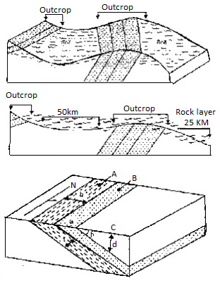
An outcrop is simply defined as an exposure of solid rock on the surface of the earth.
Outcrop Dimensions
The width or breadth of the outcrop of a particular bed is given by the distance between the top and bottom edges of the bed as measured on the surface of the ground in a direction perpendicular to the strike of that particular bed
Many variations are induced in the breadth of an outcrop of a rock by the topography of the area.
The thickness of a particular layer or bed is the perpendicular distance between the top and bottom surface of the same layer as seen in a vertical section at right angles to the strike of the layer
The depth to a particular layer or bed at any place from the surface, if believed to be present based on general geology and dip of the formation, is given by the perpendicular distance between the ground surface and the top surface of that particular layer.
When the ground surface is horizontal, depth d to the bedrock of the known dip may be obtained by the relationship
D = aC x tan b
Where is the angle of true dip of the bed exposed at a place, say at B and C is the distance from that exposure to the place C where it is desired to find out the depth to that bedrock.
Inlier and Outlier
An inlier is an area of older rocks surrounded by younger rocks. Inliers are typically formed by the erosion of overlying younger rocks to reveal a limited exposure of the older underlying rocks. Faulting or folding may also contribute to the observed outcrop pattern. A classic example from Great Britain is that of the inlier of folded Ordovician and Silurian rocks at Horton in Ribblesdale in North Yorkshire which is surrounded by the younger flat-lying Carboniferous Limestone. The location has long been visited by geology students and experts. Another example from South Wales is the Usk Inlier in Monmouthshire where Silurian age rocks are upfolded amidst Old Red Sandstone rocks of Devonian age.
A similar outcrop pattern that results from movement on a thrust fault followed by erosion may be termed a window.
Conversely, an outlier is an area of younger rock surrounded by older rocks. An outlier is typically formed when sufficient erosion of surrounding rocks has taken place to sever the younger rock's original continuity with a larger mass of the same younger rocks nearby.
Discontinuities in rock
Any structural or geological feature that changes or alters the homogeneity of a rock mass can be considered a discontinuity. Discontinuities constitute a tremendous range, from structures which are sometimes thousands of meters in extent down to - per definition - mm size, see Fig. 2-4
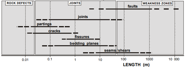
The different types, such as faults, dykes, bedding planes, tension cracks, etc. have completely different engineering significance. The roughness, nature of their contacts, degree, and nature of weathering, type and amount of gouge, and susceptibility to groundwater flow will vary greatly from one type of discontinuity to another since their cause, age, and history of development are fundamentally different. The effect on rock masses due to these localized discontinuities varies considerably over any given region depending on structure, composition, and type of discontinuity. The great influence of discontinuities upon rock mass behavior calls for special attention to these features when characterizing rock masses for practical applications. Joints and faults have numerous variations in the earth's crust, this is probably the main reason that it has been so difficult to carry out common observation and description methods.
Q7) What do you mean by folds of rock?
A7)
Folds
When rocks deform in a ductile manner, instead of fracturing to form faults or joints, they may bend or fold, and the resulting structures are called folds. Folds result from compressional stresses or shear stresses acting over considerable time. Because the strain rate is low and/or the temperature is high, rocks that we normally consider brittle can behave in a ductile manner resulting in such folds.
The geometry of Folds - Folds are described by their form and orientation. The sides of a fold are called limbs. The limbs intersect at the tightest part of the fold, called the hinge. A line connecting all points on the hinge is called the fold axis. An imaginary plane that includes the fold axis and divides the fold as symmetrically as possible is called the axial plane of the fold.
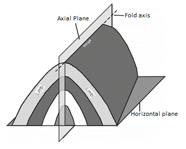
We recognize several different kinds of folds.
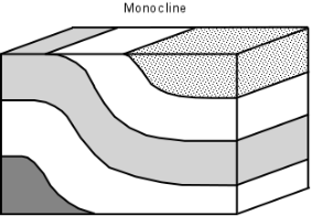
Monoclines are the simplest types of folds. Monoclines occur when horizontal strata are bent upward so that the two limbs of the fold are still horizontal.
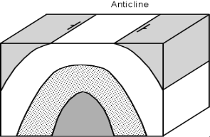
Anticlines are folds where the originally horizontal strata have been folded upward, and the two limbs of the fold dip away from the hinge of the fold.
Synclines are folds where the originally horizontal strata have been folded downward, and the two limbs of the fold dip inward toward the hinge of the fold. Synclines and anticlines usually occur together such that the limb of a syncline is also the limb of an anticline.
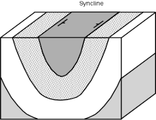
In the diagrams above, the fold axes are horizontal, but if the fold axis is not horizontal the fold is called a plunging fold and the angle that the fold axis makes with a horizontal line is called the plunge of the fold.
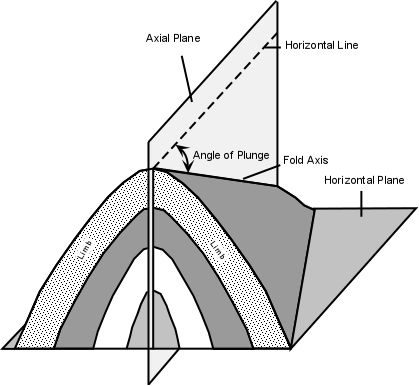
Note that if a plunging fold intersects a horizontal surface, we will see the pattern of the fold on the surface.
Domes and Basins are formed as a result of vertical crustal motion. Domes look like an overturned bowl and result from crustal upwarping. Basins look like a bowl and result from subsidence.
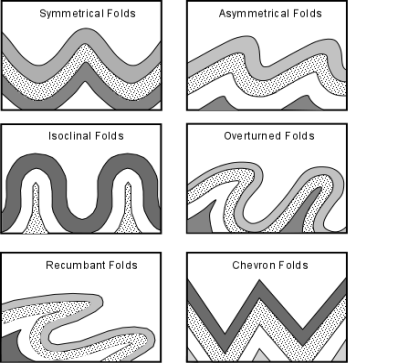
Folds are described by the severity of folding. An open fold has a large angle between limbs, a tight fold has a small angle between limbs.
Further classification of folds include:
- If the two limbs of the fold dip away from the axis with the same angle, the fold is said to be a symmetrical fold.
- If the limbs dip at different angles, the folds are said to be asymmetrical folds.
- If the compressional stresses that cause the folding are intense, the fold can close up and have limbs that are parallel to each other. Such a fold is called an isoclinal fold (iso means same, and cline means angle, so isoclinal means the limbs have the same angle). Note the isoclinal fold depicted in the diagram below is also a symmetrical fold.
- If the folding is so intense that the strata on one limb of the fold become nearly upside down, the fold is called an overturned fold.
- An overturned fold with an axial plane that is nearly horizontal is called a recumbent fold.
- A fold that has no curvature in its hinge and straight-sided limbs that form a zigzag pattern is called a chevron fold.
Q8) Explain what do you mean by fold and how they are form, what are types of faults explain in detail.
A8) Folds and Topography
Since different rocks have different resistance to erosion and weathering, erosion of folded areas can lead to a topography that reflects the folding. Resistant strata would form ridges that have the same form as the folds, while less resistant strata will form valleys.
How Folds Form
Folds develop in two ways:
- Flexural folds form when layers slip as stratified rocks are bent. This results in the layers maintaining their thickness as they bend and slide over one another. These are generally formed due to compressional stresses acting from either side.
- Flow folds form when rocks are very ductile and flow like a fluid. Different parts of the fold are drawn out by this flow to different extents resulting in layers becoming thinner in some places and thicker in outer places. The flow results in shear stress that smear out the layers.
- Folds can also form in relationship to the faulting of other parts of the rock body. In this case, the more ductile rocks bend to conform to the movement on the fault.
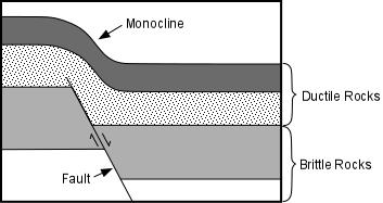
Also since even ductile rocks can eventually fracture under high stress, rocks may fold up to a certain point then fracture to form a fault.
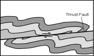
Folds and Metamorphic Foliation
As we saw in our discussion of metamorphic rocks, foliation is a planar fabric that develops in rocks subject to compressional stress during metamorphism. It may be present as flattened or elongated grains, with the flattening occurring perpendicular to the direction of compressional stress. It also results from the reorientation, recrystallization, or growth of sheet silicate minerals so that their sheets become oriented perpendicular to the compressional stress direction. Thus, we commonly see a foliation that is parallel to the axial plane of the fold.
The Shearing of rock during metamorphism can also draw out grains in the direction of shear.
Faults
Faults occur when brittle rocks fracture and there is an offset along the fracture. When the offset is small, the displacement can be easily measured, but sometimes the displacement is so large that it is difficult to measure.
Types of Faults
Faults can be divided into several different types depending on the direction of relative displacement. Since faults are planar features, the concept of strike and dip also applies, and thus the strike and dip of a fault plane can be measured. One division of faults is between dip-slip faults, where the displacement is measured along the dip direction of the fault, and strike-slip faults where the displacement is horizontal, parallel to the strike of the fault.
Some types of faults:
- Dip Slip Faults - Dip slip faults are faults that have an inclined fault plane and along which the relative displacement or offset has occurred along the dip direction. Note that in looking at the displacement on any fault we don't know which side moved or if both sides moved, all we can determine is the relative sense of motion.
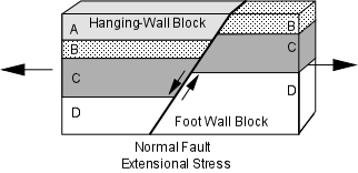
- Normal Faults - are faults that result from horizontal tensional stresses in brittle rocks and where the hanging-wall block has moved down relative to the footwall block.
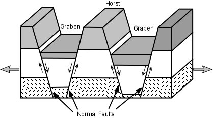
Horsts & Grabens - Due to the tensional stress responsible for normal faults, they often occur in a series, with adjacent faults dipping in opposite directions. In such a case the down-dropped blocks form grabens and the uplifted blocks form horsts. In areas where tensional stress has recently affected the crust, the grabens may form rift valleys and the uplifted horst blocks may form linear mountain ranges. The East African Rift Valley is an example of an area where a continental extension has created such a rift. The basin and range province of the western U.S. (Nevada, Utah, and Idaho) is also an area that has recently undergone crustal extension. In the basin and range, the basins are elongated grabens that now form valleys, and the ranges are uplifted horst blocks.
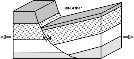
Half-Grabens - A normal fault that has a curved fault plane with the dip decreasing with depth can cause the down-dropped block to rotate. In such a case a half-graben is produced, called such because it is bounded by only one fault instead of the two that form a normal graben.
- Reverse Faults - are faults that result from horizontal compressional stresses in brittle rocks, where the hanging-wall block has moved up relative to the footwall block.
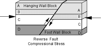
A Thrust Fault is a special case of a reverse fault where the dip of the fault is less than 45°. Thrust faults can have considerable displacement, measuring hundreds of kilometers, and can result in older strata overlying younger strata.
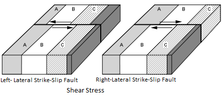
Strike-Slip Faults - are faults where the relative motion on the fault has taken place along a horizontal direction. Such faults result from shear stresses acting in the crust. Strike-slip faults can be of two varieties, depending on the sense of displacement. To an observer standing on one side of the fault and looking across the fault, if the block on the other side has moved to the left, we say that the fault is a left-lateral strike-slip fault. If the block on the other side has moved to the right, we say that the fault is a right-lateral strike-slip fault. The famous San Andreas Fault in California is an example of a right-lateral strike-slip fault. Displacements on the San Andreas fault are estimated at over 600 km.
Evidence of Movement on Faults
Since movement on a fault involves rocks sliding past each other there may be left evidence of movement in the area of the fault plane.
• Fault Breccias are crumbled-up rocks consisting of angular fragments that were formed as a result of grinding and crushing movement along a fault. When the rock is broken into clay or silt size particles as a result of slippage on the fault, it is referred to as fault gouge.
• Slickensides are scratch marks that are left on the fault plane as one block moves relative to the other. Slickensides can be used to determine the direction and sense of motion on a fault.
• Mylonite - Along some faults rocks are sheared or drawn out by ductile deformation along the fault. This results in a type of localized metamorphism called dynamic metamorphism (also called cataclastic metamorphism. The resulting rock is a fine-grained metamorphic rock show evidence of shear, called a mylonite. Faults that show such ductile shear are referred to as shear zones.
Q9) What do you mean by joints, explain their types in detail.
A9)
Joints: Planar discontinuities involving no relative displacement of the adjacent blocks. Joints develop during the exhumation of rocks following erosion of the overburden. Joints result from contraction and expansion due to cooling and decompression respectively.
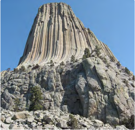
Fig: Columnar joint in
Stylolites and stylolitic joints:
Stylolitic joints are discontinuities that result from a deformation mechanism called "pressure-solution". They form through stress-induced dissolution along an irregular surface. Dissolution is triggered by stress concentration at the contact between grains. This process puts into solution molecules detached from minerals and clastic grains.
Stylolitic joints are often darker than their host rocks as iron-coated insoluble particles accumulate in the joint. In section, stylolitic joints are made of tooth-like cones. The cone's axes can be either perpendicular to the joint or can make an angle, but they always point in the direction of the maximum stress at the time of their formation.
Extensional Fractures and Shear Fractures
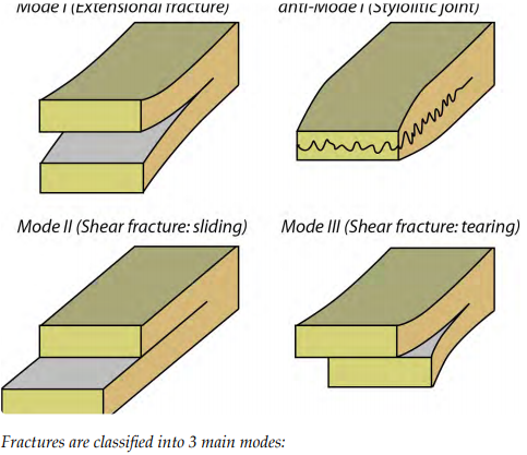
Fractures are discontinuities with limited displacement. They form when applied stress reaches the yielding threshold, i.e. the stress at which rock fractures. There are two types of fractures classified into 3 modes:
- Extensional Fractures form when the adjacent blocks move away from each other in a direction sub perpendicular to the fracture plane. The direction of opening of the fracture is parallel to that of the least resistance (i.e. the least stress). Often, extensional fractures define the "enéchelon" array or even "conjugated enéchelon array". Extensional fractures are also known as “tension gashes”. Very often these fractures are cemented with minerals that precipitate from the solution filling the rock’s pore space. Quartz in silica-rich rocks and calcite in carbonate-rich rocks commonly seal the fractures.
Extensional fractures and stylolitic joints are often associated and form Mode 1 and anti-Mode 1 of fracturing. Together they reveal the orientation of the three principal stress axes. This micro-structure association forms the basis of paleostress analysis, which consistsof mapping stress trajectories.
- Shear Fractures involve the displacement of adjacent blocks parallel to the fracture plane. As adjacent blocks slip along each other deformation affected the region of contact (i.e. damage zone). Drag folds and small offset in pre-existing layering in the damage zone help to infer the kinematic of shear fractures. In structural geology, we called "kinematic of a fault" or "kinematic of a shear fracture" the relative sense of motion parallel to the discontinuity.
- Shear fractures exist at any scale from microns to hundreds of kilometers and are often seismogenic (i.e. they are associated with earthquakes).
Importance of structural elements in engineering operations.
The study of geologic structures has been of prime importance in economic geology, both petroleum geology, and mining geology. Folded and faulted rock strata commonly form traps that accumulate and concentrate fluids such as petroleum and natural gas. Similarly, faulted and structurally complex areas are notable as permeable zones for hydrothermal fluids, resulting in concentrated areas of base and precious metal ore deposits. Veins of minerals containing various metals commonly occupy faults and fractures in structurally complex areas. These structurally fractured and faulted zones often occur in association with intrusive igneous rocks. They often also occur around geologic reef complexes and collapse features such as ancient sinkholes. Deposits of gold, silver, copper, lead, zinc, and other metals, are commonly located in structurally complex areas.
Structural geology is a critical part of engineering geology, which is concerned with the physical and mechanical properties of natural rocks. Structural fabrics and defects such as faults, folds, foliations, and joints are internal weaknesses of rocks that may affect the stability of human-engineered structures such as dams, road cuts, open-pit mines, and underground mines or road tunnels.
Geotechnical risk, including earthquake risk, can only be investigated by inspecting a combination of structural geology and geomorphology. Besides, areas of karst landscapes that reside atop caverns, potential sinkholes, or other collapse features are of particular importance for these scientists. Also, areas of steep slopes are potential collapse or landslide hazards.
Environmental geologists and hydrogeologists need to apply the tenets of structural geology to understand how geologic sites impact (or are impacted by) groundwater flow and penetration. For instance, a hydrogeologist may need to determine if seepage of toxic substances from waste dumps is occurring in a residential area or if salty water is seeping into an aquifer.
Plate tectonics is a theory developed during the 1960s which describes the movement of continents by way of the separation and collision of crustal plates. It is in a sense structural geology on a planet scale and is used throughout structural geology as a framework to analyze and understand global, regional, and local scale features.
Q10) Explain consequences of failure as land sliding, stylolite and stylolitic joint in detail.
A10) Consequences of failure as land sliding
Landslides are downslope movements of masses of soil and/or rock. They can cause some of the most spectacular damage attributable to earth movement or ground movement. Landslides include mudflows ("mudslides"), earth slumps, rockfalls, and other types of slope failures. Landslides can be fast or slow, wet or dry, small or large, shallow or deep, and reactivated or brand new. Triggering mechanisms can include rainstorms, landscape irrigation, broken pipelines, grading, inadequate surface drainage, erosion, earthquakes, and other natural phenomena and human activities. Fast-moving mudflows and debris flows are of particular concern in wildfire burn areas. Slope instability is a complex phenomenon that includes not only landslides but more subtle processes such as soil creep.
Buildings and infrastructure such as transportation facilities and pipelines located within the boundaries of a landslide or in the path of a landslide can be damaged or destroyed. Slope movements do not need to be large to be destructive. Slope creep or small, early-stage landslide movements can cause substantial structural damage to critical facilities such as dams and pipelines, potentially resulting in major economic damage and loss of life. Conversely, earth movements initially suspected to be caused by landslides might be determined to be the result of other processes such as fill settlement, a heave of expansive soil or bedrock, or hydrocompaction of collapsible soil upon wetting.
Erosion is the movement of individual grains, rather than masses, of soil by water or wind. Cumulatively, this persistent grain-by-grain movement can also cause significant damage. Rapid coastal erosion during a period of high surf or a hurricane storm surge can undermine buildings, roads, and other coastal facilities. River scour is riverbed erosion that typically occurs during periods of high flow, deepening river channels. This can uncover bridge pier foundations and buried pipelines, or undermine levee slopes, risking potential failure. Erosion can also occur underground, creating linear cavities by a process known as “piping” in which soil particles are carried away by seeping groundwater. This hidden threat is a particular concern in the siting, design, construction, and failure analysis of dams.
Stylolites and stylolitic joints:
Stylolitic joints are discontinuities that result from a deformation mechanism called "pressure-solution". They form through stress-induced dissolution along an irregular surface. Dissolution is triggered by stress concentration at the contact between grains. This process puts into solution molecules detached from minerals and clastic grains.
Stylolitic joints are often darker than their host rocks as iron-coated insoluble particles accumulate in the joint. In section, stylolitic joints are made of tooth-like cones. The cone's axes can be either perpendicular to the joint or can make an angle, but they always point in the direction of the maximum stress at the time of their formation.
Q11) Explain in detail impact of earthquake in detail.
A11) The Impacts of Earthquakes
Some of the common impacts of earthquakes include structural damage to buildings, fires, damage to bridges and highways, initiation of slope failures, liquefaction, and tsunami. The types of impacts depend to a large degree on where the earthquake is located: whether it is predominantly urban or rural, densely or sparsely populated, highly developed or underdeveloped, and of course on the ability of the infrastructure to withstand shaking.
As an example of the 1985 Mexico earthquake, the geological foundations on which structures are built can have a significant impact on earthquake shaking. When an earthquake happens, the seismic waves produced have a wide range of frequencies. The energy of the higher frequency waves tends to be absorbed by solid rock, while the lower frequency waves (with periods slower than one second) pass through the solid rock without being absorbed, but are eventually absorbed and amplified by soft sediments. It is therefore very common to see much worse earthquake damage in areas underlain by soft sediments than in areas of solid rock. A good example of this is in the Oakland area near San Francisco, where parts of a two-layer highway built on soft sediments collapsed during the 1989 Loma Prieta earthquake (Fig).
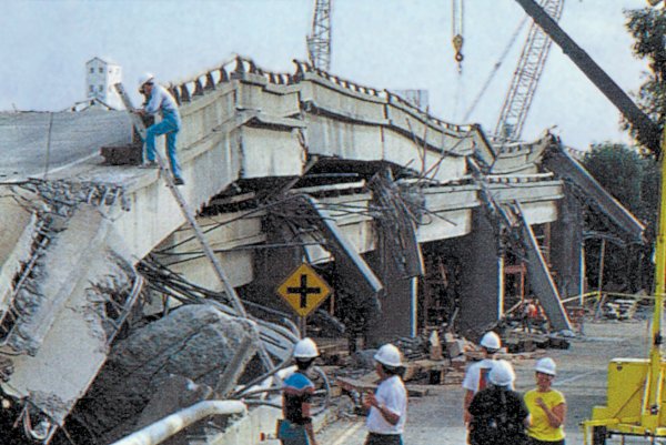
Fig. Collapsed freeway
Building damage is also greatest in areas of soft sediments, and multi-story buildings tend to be more seriously damaged than smaller ones. Buildings can be designed to withstand most earthquakes, and this practice is increasingly applied in earthquake-prone regions. Turkey is one such region, and even though Turkey had a relatively strong building code in the 1990s, adherence to the code was poor, as builders did whatever they could to save costs, including using inappropriate materials in concrete and reducing the amount of steel reinforcing. The result was that there were over 17,000 deaths in the 1999 M7.6 Izmit earthquake (Figure 4.29). After two devastating earthquakes that year, Turkish authorities strengthened the building code further, but the new code has been applied only in a few regions, and enforcement of the code is still weak, as revealed by the amount of damage from an M7.1 earthquake in eastern Turkey in 2011.
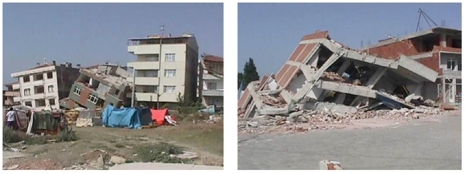
Fig. Buildings damaged by the 1999 earthquake in the Izmit area, Turkey
Fires are commonly associated with earthquakes because fuel pipelines rupture and electrical lines are damaged when the ground shakes (Fig 4.30). Most of the damage in the great 1906 San Francisco earthquake was caused by massive fires in the downtown area of the city (Fig 4.31). Some 25,000 buildings were destroyed by those fires, which were fuelled by broken gas pipes. Fighting the fires was difficult because water mains had also ruptured. The risk of fires can be reduced through P-wave early warning systems if utility operators can reduce pipeline pressure and close electrical circuits.
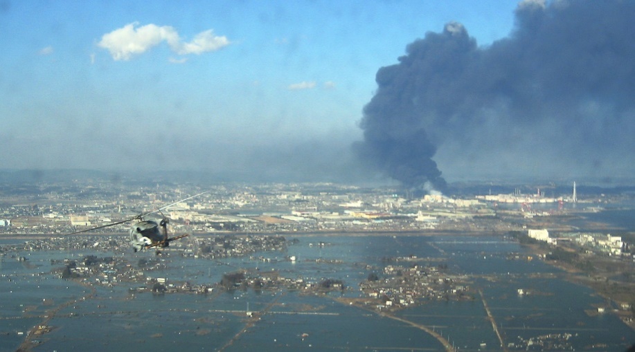
Fig. An oil refinery is on fire, and a vast area has been flooded by a tsunami.

Fig. Fires in San Francisco
Earthquakes are important triggers for failures on slopes that are already weak. An example is the Las Colinas slide in the city of Santa Tecla, El Salvador, which was triggered by an M7.6 offshore earthquake in January 2001 (Fig).
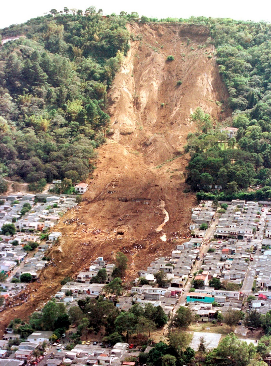
Fig. The Las Colinas debris flow at Santa Tecla
Ground shaking during an earthquake can be enough to weaken rock and unconsolidated materials to the point of failure, but in many cases, the shaking also contributes to a process known as liquefaction, in which an otherwise solid body of sediment is transformed into a liquid mass that can flow. When water-saturated sediments are shaken, the grains become rearranged to the point where they are no longer supporting one another. Instead, the water between the grains is holding them apart and the material can flow. Liquefaction can lead to the collapse of buildings and other structures that might be otherwise undamaged. A good example is the collapse of apartment buildings during the 1964 Niigata earthquake (M7.6) in Japan (Fig 4.33). Liquefaction can also contribute to slope failures and to fountains of sandy mud (sand volcanoes) in areas where there is loose saturated sand beneath a layer of more cohesive clay.
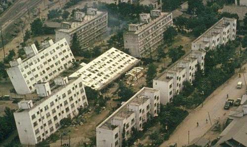
Fig. Collapsed apartment buildings
Q12) Explain the strength of igneous rock structure.
A12)
Strength of Igneous rock structures.
The uniaxial compressive strength of a rock material constitutes the highest strength limit of the rock mass of which it forms a part. It is determined following the standard laboratory procedures. For rock mass classification, the use of the well-known point load strength index can be useful as the index can be determined in the field on rock core retrieved from borings and the core does not require any specimen preparation. Knowing the rock type and rock material hardness, it is possible for the experienced engineer or engineering geologist to make fairly accurate estimates of rock material strength. These can be readily verified by uniaxial compressive strength or point load tests. A simple estimate can be made from the field test in Table 1. The hammer tests should be made with a 2-lb hammer on pieces about 4 in. (10 cm) thick placed on a solid, hard surface, and tests with the hands should be made on pieces about 1.5 in. (4 cm) thick. The pieces must not have incipient fractures, and therefore several should be tested. The sound tests, which are the only accessory, should be made on solid outcrops or fragments thicker than 1 ft (0.3 m).

Table: Field classification of rock hardness

Table: The classification of rock strength used by Bieniawski
It should be noted that the boundary between rock and soil is defined in terms of the uniaxial compressive strength and not in terms of weathering. A material with a strength ≤ of 1 MPa is considered a rock.
A SCALE OF STRENGTH
- Loose. Sediment flows when dry and thus cannot be sampled in aggregate.
- Very friable. Sediment crumbles so easily that pieces are difficult to collect intact.
- Friable. Sediment crumbles under light pressure in the hands.
- Somewhat friable. Rock breaks in the hands under moderate pressure.
- The firm, slightly friable. Rock breaks with difficulty in the hands but readily by hammer blows, sounding a dull "whop"
- Weak, nonfriable. Rock cannot be broken in the hands but breaks under the light hammer blow, sounding "whop"
- Moderately strong. Rock breaks under the moderate hammer blow, sounding "whap"
- Strong. Rock breaks under the hard hammer blow, sounding "whack," with a ring.
- Very strong. Rock difficult to break with a hammer, sounding "boink."
- Unusually strong. Rock impossible to break with a hammer, sounding like steel.
A SCALE OF ROCK HARDNESS
- Soft. All rocks weaker than 5 on the scale-of-strength above.
- Moderately hard. Slightly friable or nonfriable rocks consisting mainly of soft minerals, like carbonates, sulfates, micas, and clays.
- Hard. Nonfriable rocks consisting almost entirely of minerals with hardnesses of 4, 5, or 6 on the Mohs scale, and quartz-rich rocks with the strength of 6 or 7.
- Very hard. Rocks stronger than 7 on the scale above and consisting mainly of minerals harder than 6 on the Mohs scale.

Q13) Explain evidence of movement on faults, fold and metamorphic foliation, inlier and outlier in detail with example.
A13) Evidence of Movement on Faults
Since movement on a fault involves rocks sliding past each other there may be left evidence of movement in the area of the fault plane.
- Fault Breccias are crumbled-up rocks consisting of angular fragments that were formed as a result of grinding and crushing movement along a fault. When the rock is broken into clay or silt size particles as a result of slippage on the fault, it is referred to as fault gouge.
- Slickensides are scratch marks that are left on the fault plane as one block moves relative to the other. Slickensides can be used to determine the direction and sense of motion on a fault.
- Mylonite - Along some faults rocks are sheared or drawn out by ductile deformation along the fault. This results in a type of localized metamorphism called dynamic metamorphism (also called cataclastic metamorphism. The resulting rock is a fine-grained metamorphic rock show evidence of shear, called a mylonite. Faults that show such ductile shear are referred to as shear zones.
Folds and Metamorphic Foliation
As we saw in our discussion of metamorphic rocks, foliation is a planar fabric that develops in rocks subject to compressional stress during metamorphism. It may be present as flattened or elongated grains, with the flattening occurring perpendicular to the direction of compressional stress. It also results from the reorientation, recrystallization, or growth of sheet silicate minerals so that their sheets become oriented perpendicular to the compressional stress direction. Thus, we commonly see a foliation that is parallel to the axial plane of the fold.
The Shearing of rock during metamorphism can also draw out grains in the direction of shear.
Inlier and Outlier
An inlier is an area of older rocks surrounded by younger rocks. Inliers are typically formed by the erosion of overlying younger rocks to reveal a limited exposure of the older underlying rocks. Faulting or folding may also contribute to the observed outcrop pattern. A classic example from Great Britain is that of the inlier of folded Ordovician and Silurian rocks at Horton in Ribblesdale in North Yorkshire which is surrounded by the younger flat-lying Carboniferous Limestone. The location has long been visited by geology students and experts. Another example from South Wales is the Usk Inlier in Monmouth shire where Silurian age rocks are upfolded amidst Old Red Sandstone rocks of Devonian age.
A similar outcrop pattern that results from movement on a thrust fault followed by erosion may be termed a window.
Conversely, an outlier is an area of younger rock surrounded by older rocks. An outlier is typically formed when sufficient erosion of surrounding rocks has taken place to sever the younger rock's original continuity with a larger mass of the same younger rocks nearby.
Q13) What do you mean by dip? Explain their types. What is strike and outcrop and width of outcrop.
A14) Types of Dip
There are two types of Dips, namely:
(i). True Dip and
(ii). Apparent Dip
(i). True Dip – It is the maximum amount of slope along a line perpendicular to the strike, in other words, it is the maximum slope for the horizontal. It may also be stated as the geographical direction along which the line of quickest descent slopes down.
(ii). Apparent Dip – Along any direction other than that of the true dip, the gradient is scheduled to be much less, and therefore it is defined as the apparent dip. The apparent dip of any bed towards any direction must always be less than its true dip.
Strike
The direction of the line along which an inclined bed intersects a horizontal plane is known as the strike of the bed. It is a scalar quantity, as it has only one component, i.e., direction but not magnitude. The strike of the bed is independent of its amount of dip.
Importance of Dip and Strike
In structural geology, Strike and Dip are quite important for the following purposes:
(a) To determine the younger bed of formation. It is well known that younger beds will always be found in the direction of Dip. If we go in the direction of dip, relatively beds of a younger age will be found to out-crop and older rocks in the opposite direction.
(b) In the classification, and nomenclature of folds, faults, joints, and unconformities, the nature of dip and strike is of paramount significance. Thus the attitude, which refers to the three-dimensional orientation of some geological structures, is defined by their dip and strike.
Outcrop and width of outcrop
In the mountainous and sub-mountainous tracts and also in shallow plains, exposures of rocks may be easily seen forming sides of valleys or caps of hills or even uplands and slopes in level fields.
An outcrop is simply defined as an exposure of solid rock on the surface of the earth.
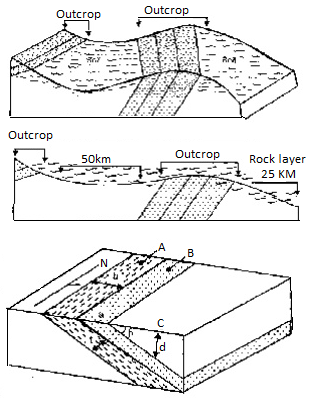
Outcrop Dimensions
The width or breadth of the outcrop of a particular bed is given by the distance between the top and bottom edges of the bed as measured on the surface of the ground in a direction perpendicular to the strike of that particular bed
Many variations are induced in the breadth of an outcrop of a rock by the topography of the area.
The thickness of a particular layer or bed is the perpendicular distance between the top and bottom surface of the same layer as seen in a vertical section at right angles to the strike of the layer
The depth to a particular layer or bed at any place from the surface, if believed to be present based on general geology and dip of the formation, is given by the perpendicular distance between the ground surface and the top surface of that particular layer.
When the ground surface is horizontal, depth d to the bedrock of the known dip may be obtained by the relationship
D = aC x tan b
Where is the angle of true dip of the bed exposed at a place, say at B and C is the distance from that exposure to the place C where it is desired to find out the depth to that bedrock.
Q14) What is Unconformity?
A15)
An unconformity is a buried erosion or non-depositional floor keeping apart rock loads or strata of various ages, indicating that sediment deposition become now no longer continuous. The rocks above an unconformity are more youthful than the rocks beneath (except the series has been overturned).
N unconformity is a buried erosional or non-depositional floor keeping apart rock hundreds or strata of various ages, indicating that sediment deposition became now no longer continuous. In general, the older layer became uncovered to erosion for an c programming language of time earlier than deposition of the more youthful layer, however the time period is used to explain any destroy within side the sedimentary geologic document. The importance of angular unconformity (see below) became proven with the aid of using James Hutton, who located examples of Hutton's Unconformity at Jedburgh in 1787 and at Siccar Point in 1788.[1][2] The rocks above an unconformity are more youthful than the rocks beneath (until the collection has been overturned). An unconformity represents time at some point of which no sediments had been preserved in a location or had been in the end eroded earlier than the subsequent deposition. The nearby document for that point c programming language is lacking and geologists have to use different clues to find out that a part of the geologic records of that area. The c programming language of geologic time now no longer represented is known as a hiatus. It is a sort of relative dating.
Types Disconformities
Disconformity
A disconformity is an unconformity among parallel layers of sedimentary rocks which represents a duration of abrasion or non-deposition. Disconformities are marked through functions of subaerial erosion. This sort of erosion can go away channels and paleosols within side the rock record. Nonconformity Non conformity A nonconformity exists among sedimentary rocks and metamorphic or igneous rocks whilst the sedimentary rock lies above and changed into deposited at the pre-current and eroded metamorphic or igneous rock. Namely, if the rock underneath the smash is igneous or has misplaced its bedding because of metamorphism, the aircraft of juncture is a nonconformity.
Angular unconformity
An angular unconformity is an unconformity in which horizontally parallel strata of sedimentary rock are deposited on tilted and eroded layers, generating an angular discordance with the overlying horizontal layers. The entire series may also later be deformed and tilted through in addition orogenic activity. A regular case records is offered through the paleo tectonic evolution of the Brian çonnais realm (Swiss and French Prealps) in the course of the Jurassic.
Para conformity
Para conformity: A para conformity is a sort of unconformity wherein the sedimentary layers above and underneath the unconformity is parallel, however there's no apparent erosional smash among them. A smash in sedimentation is indicated, for example, through fossil evidence. It is likewise known as non-depositional unconformity or pseudo conformity. Short para conformities are known as diastems. Buttress unconformity A buttress unconformity takes place whilst more youthful bedding is deposited towards older strata for this reason influencing its bedding structure. Blended unconformity A mixed unconformity is a sort of disconformities or nonconformity without a wonderful separation aircraft or contact, now and again along with soils, pale sols, or beds of pebbles derived from the underlying rock
An unconformity is a buried erosional or non-depositional floor that separates different-age rock loads or strata, indicating that the deposition of sediments changed into now no longer continuous. The older layer changed into usually uncovered to erosion for an c language of time earlier than the more youthful layer changed into deposed, however the time period is used to explain any wreck within side the sedimentary geological record.
Q15) What is Consequences of failure as land sliding?
A16)
Landslides are down slope movements of masses of soil and/or rock. They can cause some of the most spectacular damage attributable to earth movement or ground movement. Landslides include mudflows ("mudslides"), earth slumps, rock falls, and other types of slope failures. Landslides can be fast or slow, wet or dry, small or large, shallow or deep, and reactivated or brand new. Triggering mechanisms can include rainstorms, landscape irrigation, broken pipelines, grading, inadequate surface drainage, erosion, earthquakes, and other natural phenomena and human activities. Fast-moving mudflows and debris flows are of particular concern in wildfire burn areas. Slope instability is a complex phenomenon that includes not only landslides but more subtle processes such as soil creep.
Buildings and infrastructure such as transportation facilities and pipelines located within the boundaries of a landslide or in the path of a landslide can be damaged or destroyed. Slope movements do not need to be large to be destructive. Slope creep or small, early-stage landslide movements can cause substantial structural damage to critical facilities such as dams and pipelines, potentially resulting in major economic damage and loss of life. Conversely, earth movements initially suspected to be caused by landslides might be determined to be the result of other processes such as fill settlement, a heave of expansive soil or bedrock, or hydro compaction of collapsible soil upon wetting.
Erosion is the movement of individual grains, rather than masses, of soil by water or wind. Cumulatively, this persistent grain-by-grain movement can also cause significant damage. Rapid coastal erosion during a period of high surf or a hurricane storm surge can undermine buildings, roads, and other coastal facilities. River scour is riverbed erosion that typically occurs during periods of high flow, deepening river channels. This can uncover bridge pier foundations and buried pipelines, or undermine levee slopes, risking potential failure. Erosion can also occur underground, creating linear cavities by a process known as “piping” in which soil particles are carried away by seeping groundwater. This hidden threat is a particular concern in the siting, design, construction, and failure analysis of dams.