Unit – 4
Torsion
Q1) Derive the Torsion equation.
A1) Torsion equation derivation
Following are the assumptions made for the derivation of torsion equation:
- The material is homogeneous (elastic property throughout)
- The material should follow Hook’s law
- The material should have shear stress proportional to shear strain
- The cross-sectional area should be plane
- The circular section should be circular
- Every diameter of the material should rotate through the same angle
- The stress of the material should not exceed the elastic limit
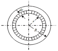
Consider a solid circular shaft with radius R that is subjected to a torque T at one end and the other end under the same torque.
T = Maximum twisting torque or twisting moment
D = Diameter of shaft
R = Radius of shaft
J = Polar moment of Inertia
τ= Maximum Permissible Shear stress (Fixed for given material)
G = Modulus of rigidity
θ= Angle of twist (Radians) = angle D'OD L = Length of shaft.
 = Angle D'CD = Angle of Shear strain

Then, Torsion equation is: T/J = τ/R = G. θ /L
Let the shaft is subjected to a torque or twisting moment 'T'. And hence every C.S. Of this shaft will be subjected to shear stress.
Now distortion at the outer surface = DD'
Shear strain at outer surface = Distortion/Unit length tan = DD'/CD
i.e. shear stress at the outer surface
(tan =) = DD'/L or = DD'/L ...(i)
Now
DD' = R.θ or  = = R .θ /L ...(ii)
Now G = Shear stress induced/shear strain produced
G = τ / (R. θ /L);
Or; τ/R = G. θ /L …..(A);
This equation is called Stiffness equation.
Hear G, θ, L are constant for a given torque 'T'. That is proportional to R
If τ r be the intensity of shear stress at any layer at a distance 'r' from canter of the shaft, then;

 of elementary ring about an axis perpendicular to the plane passing
Through center of circle.
 Polar Moment of Inertia
Now from equation (ii) T = (τ/R) J or
τ/R = T/J; ..(B)
This equation is called as strength equation
The combined equation A and B; we get
T/J = τ/R = G. θ /L
This equation is called as Torsion equation.
From the relation T/J = τ/R
We have
T = τ .J/R = τ .ZP
For the given shaft IP and Rare constants and IP/R is thus constant and is called as polar modulus (ZP) of the shaft section.
Polar modulus of section is thus measure of strength of shaft in the torsion.
Q2) What is buffer spring? Differentiate between close coiled and open coiled helical springs.
A2) Buffer spring:
Buffer spring is mostly used in Railway wagons. The shock between two colliding bodies may be softened or cushioned by means of buffers.
Close-coiled spring
a) Adjacent coils are very close to each other
b) Only tensile load can carry
c) Helix angle is negligible
Open- coiled spring
a) Large gap between adjacent coils
b) Tensile and compressive loads can carry.
c) Helix angle considerable
Q3) Derive the expression for close coiled helical spring-under axial force.
A3)

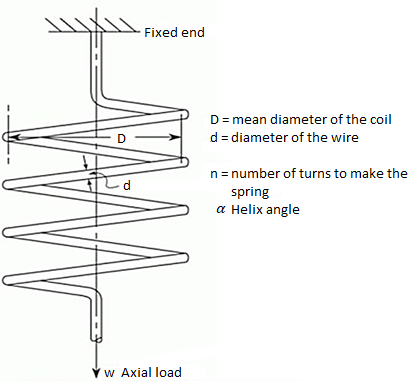
As the helix angle (angle of the turn with the horizontal) is small, axial load only causes twist in the wire of the spring. It is similar to a shaft under pure torsion. It is considered only in pure torsion and the torsion equation is used to analyze it.
Actually, stresses present will be
- Torsion shear stress
- Bending stress
- Direct shear stress
Bending stress and direct shear stresses have been found to be negligible. However, their small effect has been accounted for by Wahl stress concentration factor.
T = W x R=WxD/2
T/J = ԏ/r = Gϴ/L
J = (π/64)d4
R =radius of wire = d/2
G = Modulus of rigidity
ϴ= Angle of twist in radians
L= length of wire = 2πrn
Using T/J = ԏ /r
(WD/2)/ (π/64)d4 = ԏ /(d/2)
Α = angle of helix = 0 in a closed coil spring
Stress = ԏ= 8WD/πd3
Stress concentration factor accounts for two things
(i) Direct shear stress consideration
(ii) Stress concentration due to change in curvature
Wahl’s stress concentration factor is given by
K = (4C-1)/(4C-4)+ 0.615/C
Where C is spring index=D/d
Now actual shear stress becomes = kԏ= k 8WD/πd3
(1/2)Wδ = (1/2) Tϴ,
δ = 64 WR3n/Gd4
Stiffness = k= W/δ = Gd4/64R3n
Resilience = u = ԏ2/2G
Solid length = nd
Q4) A solid shaft of 150mm diameter is used to transmit torque. Find the maximum torque transmitted by the shaft If the maximum shear stress induced to the shaft is 45 N/mm^2.
A4)
Given:
Diameter of the shaft, D=150mm
Maximum shear stress, =45 N/mm2
Let T = Maximum torque transmitted by the shaft.
Using equation (16.4), 

Q5) The shearing stress in the solid shaft is not to exceed 40N/mm^2 when the torque transmitted is 20000N-m. Determine the minimum diameter of the shaft.
A5)
Given:
Maximum shear stress, 
Torque transmitted, 
Let  Minimum diameter of the shaft in mm.


Q6) A solid steel shaft has to transmit 75KW at 200 rpm. Taking allowable shear stress as 70 N/mm2, find suitable diameter of the shaft, if the maximum torque transmitted at each revolution exceeds the mean by 30%.
A6)
Given:
Power transmitted, 
R.P.M of the shaft, 
Shear stress, 
Let  Mean torque transmitted
 Maximum torque transmitted =1.3T
 Suitable diameter of the shaft
Power is given by the relation,


Maximum torque transmitted by a solid shaft is given by equation (16.4) as


Q7) A hollow shaft is to transmit 300 KW power at 80 r.p.m. If the shear stress is not to exceed 60N/mm2 and internal diameter is 0.6 of the external diameters, find the external and internal diameter assuming that the maximum torque is 1.4 times the mean.
A7)
Given:
Power transmitted, 
Speed of the shaft, 
Maximum shear stress, 
Internal diameter, 
Maximum torque,  times the mean torque =1.4×T
Power is given by the relation,


Now maximum torque transmitted by hollow shaft is given as-


Q8) Determine the diameter of the solid steel shaft which will transmit 90KW at 160 r.p.m. Also determine the length of the shaft if the twist must not exceed with 1 degree over the entire length. The maximum shear stress is limited to 60 N/mm^2. Take C = 8 * 10^4 N/mm^2.
A8)
Given:
Power,
Speed, 
Angle of twist, 
Maximum shear stress, =60 N/
Modulus of rigidity, 
Let  Diameter of the shaft and
 Length of the shaft
(i) Diameter of the shaft
Using equation


Now using equation


(ii) Length of the shaft
Using equation, 


Q9) A circular solid shaft transmits 75 KW power at 200 r.p.m. Calculate the shaft diameter, if the twist in the shaft is not to exceed 1 degree in 2m length of shaft and shear stress is limited to 50N/mm^2. Take) Modulus rigidity, 
A9)
Given:
Power transmitted, 
Speed of the shaft, 
Twist in the shaft, 
Length of shaft, 
Maximum shear stress, 
Modulus of rigidity, 


(i) Diameter of the shaft when maximum shear stress is limited to 50


(ii) Diameter of the shaft when the twist in the shaft is not to exceed 1


The suitable diameter of the shaft is the greater value of the diameter given by equation (i) and (ii) i.e., 80.4mm say 81 mm.
Q10) Determine the diameter of the solid shaft which transmit power of 30KW at 250 r.p.m. The maximum shear stress should not exceed 30  and twist should not be more that 1 degree in a shaft length of 2 m.
A10)
Given:
Power,
Speed, 
Maximum shear stress, =30 N/
Twist in the shaft, 
Length of shaft, 
Modulus of rigidity, 


(i) Diameter of the shaft when maximum shear stress

Maximum torque transmitted by a solid shaft is given by equation


 …….(i)
(ii) Diameter of the shaft when the twist in the shaft is not be more than 1

Where J =Polar moment of inertia of solid shaft


The suitable diameter of the shaft is the greater* of the two values given by equations (i) and (ii).
 Diameter of the shaft =124.5mm say 125 mm.
*If diameter is taken smaller of the two values say 107.5mm, then from equation.
 , the value of shear stress will be
 , the value of shear stress will be


Which is more than the given value of 30N/mm2).