Unit – 5
Axial and hoop stresses in cylinders subjected to internal pressure
Q1) Derive the expression for circumferential stress or Hoop stress developed in the wall of cylindrical shell.
A1)
Let us consider here following terms:
P = Internal fluid pressure
d = Internal diameter of thin cylindrical shell
t = Thickness of the wall of the cylinder
L = Length of the cylindrical shell
σH = Circumferential stress or hoop stress developed in the wall of the cylindrical shell.
Cylindrical shell bursting will take place if force due to internal fluid pressure will be more than the resisting force due to circumferential stress or hoop stress developed in the wall of the cylindrical shell.
In order to secure the expression for circumferential stress or hoop stress developed in the wall of the cylindrical shell, we will have to consider the limiting case i.e. force due to internal fluid pressure should be equal to the resisting force due to circumferential stress or hoop stress.
Force due to internal fluid pressure = Internal fluid pressure x Area on which fluid pressure will be acting
Force due to internal fluid pressure = P x (d x L)
Resisting force due to circumferential stress = σH x 2 L t
As we have seen above, we can write following equation as mentioned here.
Force due to internal fluid pressure = Resisting force due to circumferential stress
P x d x L = σH x 2 L t
σH = P x d / (2 t)
σH= P x d/ 2t
Longitudinal (Axial) Stress
For a cylinder closed in both ends the internal pressure creates a force along the axis of the cylinder. The longitudinal stress caused by this force can be calculated as
σL = p d / (4 t)
Where,
σl = longitudinal stress (MPa, psi)
P = Internal fluid pressure
d = Internal diameter of thin cylindrical shell
t = Thickness of the wall of the cylinder

The stresses σz in the axial direction of a cylindrical pressure vessel with closed ends are found using this same approach as seen in Fig. 3, and yielding the same A)
P (πr2) = σz(2πr) t
σz=pr/2t

However, a different view is needed to obtain the circumferential or “hoop” stresses σθ. Considering an axial section of unit length, the force balance gives 2σθ (t x 1) = p* (2r x 1)
σθ=pr/t
Q2) Derive the expression for the condition when a thin cylinder is closed at both ends and subjected to internal pressure.
A2)
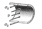
Consider a thin cylinder closed at both ends and subjected to internal pressure ‘p’ as shown in the figure. Let d=Internal diameter, t = Thickness of the wall L = Length of the cylinder.
Consider a small length ‘dl’ of the cylinder and an elementary area ‘dA’ as shown in the figure.
Consider a small length ‘dl’ of the cylinder and an elementary area ‘dA’ as shown in the figure.
Force on the elementary area,


Horizontal component of this force

Vertical component of this force

∴ Total diametrical bursting force 


∴ Resisting force (due to circumferential stress  )=2
)=2
Under equilibrium, Resisting force=Bursting force
i.e., 2
 Circumferential stress
Force due to fluid pressure= p × area on which p is acting =  (bursting force)
Force due to circumferential stress = is acting

∴ Circumferential stress,  …… (1)
Q3) Derive the expression for the thick cylinder.
A3)
Consider a thick cylinder of external radius r1 and internal radius r2, containing a fluid under pressure ‘p’ as shown in the fig.
Let ‘L’ be the length of the cylinder.
Consider an elemental ring of radius ‘r’ and thickness ‘δr’ as shown in the above figures. Let pr and (pr+ δpr) be the intensities of radial pressures at inner and outer Consider the longitudinal section XX of the ring as shown in the fig. The bursting force is evaluated by considering the projected area,
 for the inner face and
  for the inner face and
  for the outer face.
The net bursting force, 
 ×
×
Bursting force is resisted by the hoop tensile force developing at the level of the strip

Thus, for equilibrium 


Longitudinal strain is constant. Hence we have

Since  is compressive

Since  , E and μ are constants
  should be constant. Let it be equal to 2a. Thus


From (1), 


Integrating,

Where c is constant of integration. Let it be taken as  , where b is another constant.
Thus, 
 or radial stress,
Substituting it in equation 2, we get
Hoop stress, 

The equation (4) and (5) are known as “Lame’s Equations” for radial pressure and hoop stress at any specified point on the cylinder wall.
Thus  .
.
Q4) Derive the expression when sphere subjected to internal pressures.
A4)
Sphere subjected to internal pressures.
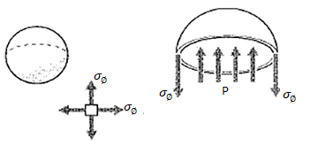
Consider a simple spherical vessel of radius r and wall thickness t, such as a round balloon. An internal pressure p induces equal biaxial tangential tensile stresses in the walls, which can be denoted using spherical rθφ coordinates as σθ and σφ.

The magnitude of these stresses can be determined by considering a free body diagram of half the pressure vessel, including its pressurized internal fluid (see Fig. 2).
The fluid itself is assumed to have negligible weight. The internal pressure generates a force of pA= p (πr2) acting on the fluid, which is balanced by the force obtained by multiplying the wall stress times its area,
σφ(2πrt) Equating these:
P (πr2) = σφ (2πrt)
σφ = pr/2t
Note that this is a statically determined result, with no dependence on the material properties. Further, note that the stresses in any two orthogonal circumferential directions are the same;
I.e., σφ= σθ.
The accuracy of this result depends on the vessel being “thin-walled,” i.e. r>>t. At the surfaces of the vessel wall, a radial stress σrmust be present to balance the pressure there. But the inner-surface radial stress is equal to p, while the circumferential stresses are p times the ratio (r/2t). When this ratio is large, the radial stresses can be neglected in comparison with the circumferential stresses.
Q5) A vessel in the shape of the spherical shell of 1.20 m internal diameter and 12 mm shell thickness is subjected to pressure of 1.6 N/mm^2. Determine the stress induces in the material of the vessel.
A)5
Given:
Internal diameter, d=1.2m=1.2×103mm
Shell thickness, t=1.2mm
Fluid pressure, p=1.6 N/mm2
The stress induced in material of spherical shell is given by

Q6) A spherical vessel 1.5 m diameter is subjected to an internal pressure of 2 N/mm^2. Find the thickness of the plate required if maximum stress is not exceed 150 N/mm^2 and joint efficiency is 75%.
A6)
Given: Diameter of shell, 
Fluid pressure, 
Stress in material, 
Joint efficiency, 
Let 
The stress induced is given by,


Q7) Find the speed of rotation of a wheel of diameter 750 mm, if the hoop stress is not exceed 120 N/mm^2. The wheel has a thin rim and density of wheel is 7200 Kg/m^3.
A7)
Given: Diameter 

Max. Hoop stress, 
Density, 


Q8) A thick spherical shell of 20 mm internal diameter is subjected to an internal fluid pressure of 7 N/mm^2. If the permissible tensile stress in the shell /material is 8 N/mm^2, find the thickness of the shell.
A8)
Given: Internal diameter =200 mm
Internal radius 
Internal fluid pressure 
Permissible tensile stress 
The radial pressure and hoop stress at any radius of spherical shell are given by

Th hoop stress,  will be maximum at the internal radius. Hence permissible tensile stress of 8 N/mm2 is the interval radius.
At x=100 mm, 
Substituting these values in equation (i), we get

At x=100 mm, 
Substituting the values in equation (iii), we get

Adding equation (iii) and (iv), we get


Substituting the value in equation (iv), we get


Substituting the values of a and b in equation (i), we get

Let  External radius of the shell.
At outside, the pressure

Substituting these values in equation (v), we get


 Thickness of the shell,
Q9) Determine the maximum and minimum hoop stress across the section of the pipe of 400 mm internal diameter and 10 mm thick, when pipe contain a fluid in the pressure of 8 N/mm^2.
A9)
Given:
Internal diameter = 400 mm
Internal radius, 
Thickness =100 mm
External diameter = 400+2×100=600 mm
External radius, 
Fluid pressure, 
At 

Now apply the boundary conditions to the above equaitons. The booundary conditions
1. At 
2. At 
Substituting these boundary conditions in equation (i), we get


Subtracting equation (iii) from (ii), we get


Substituting this value in equation (iii), we get

The values of a and b are substituted in the hoop stress.
Now hoop stress at any radius x is given by equation

At 
At 