Unit - 4
Shear strength and Stability of Slope
Q1) What is Shear strength?
A1)
- In most of the problems in soil mechanics such as those concerning the foundations of structures, earthwork engineering etc., the soil mass has to withstand shearing stresses, which are unlike in nature than the compressive stresses.
- Shearing stresses tend to displace part of the soil mass relative to rest of the soil mass, Shear strength of a soil is the capacity of the soil to resist shearing stress.
- It can be defined as the maximum value of shear stress that can be mobilized within a soil mass. If this value is equalled by the shear stress on any plane or surface at a point, failure will occur in the soil because of movement of a portion of the soil mass along that plane or surface.
- The soil is then said to have failed in shear.
- The shear strength depends upon:
- Type of soil
- Cohesion
- Compaction.
- Water content
- Internal friction
Q2) What is Mohr’s Strength and Stress Circles?
A2)
- The circle on which the co-ordinates of points showing the normal and shearing stresses on inclined planes at a given point is termed as mohr circle of stress.
- Fig. Shows a cylindrical specimen of soil subjected to normal stresses a, and o, where a major principal stress and d, minor principal stress.
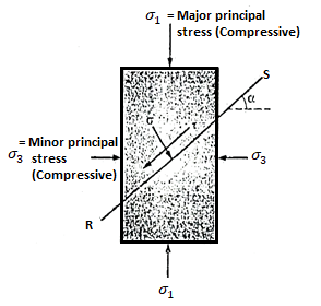
Fig.: Soil Specimen
- By taking as radius as
 and centre at C at a distance of
  on the abscissa from origin 'O' .In mohr circle of stress for soil specimen can be drawn as shown in Fig.
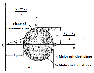
Fig.: Mohr’s stress circle for cylindrical specimen
- From the pole P a line PP1 is drawn parallel to the plane RS as shown in Fig. The co-ordinates of the point P, gives the stress and
 i.e. P, (
 ,
,  ) fm the stress circle,<P1 CB=2
- In Fig. The major principal plane is horizontal and therefore pre P is located by drawing a horizontal line through "B" and OB presents the major principal stress. The circle draws inserts at A and hence OA repents minor principal stress. Point B shows the major principal s
 ,
,  ), whereas point A shows the minor principal trees
  ,
,  )
)
Q3) Explain Mohr’s Envelope?
A3)
- As soil is a complex material, it is very difficult to give a criterion of failure and also to define the plane of failure. For a given value of
 and
and  , a Mohr's circle can be drawn by finding the stress,
  and
and  .
. - This is shown in Fig.(a). For a series of tests on the same soil, different Mohr's circles can be drawn. This is shown in Fig. (b).
- If a common tangent is drawn to all the Mohr's circles, it will represent the values of T as a function of
 , at failure condition. This common tangent is known as the strength envelope of the soil. See Fig.(b).
 - Further, if a perpendicular is drawn from the point of tangency, it will give the failure shear stress corresponding to a particular normal stress.
- The angle shown as
 , will give the angle of the failure plane. There will be two mutually perpendicular failure planes.
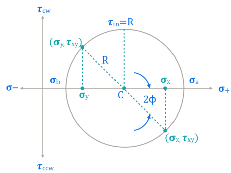
Fig.: Mohr’s Circle

Fig.: Strength envelope
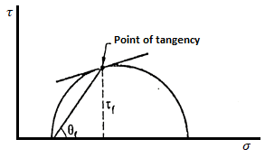
Fig.: Failure plane and Failure stress
Q4) Explain Mohr Coulomb Strength theory?
A4)
- Mainly shear failure in soil occurs by slippage of particle due to shear stress.
- Shear stress at failure normally depend upon normal stresses on the potential failure plane.
- According to Mohr soil failure is a function of normal stress applied on the soil.
i.e.  f=f(
f=f( )
)
 f = shear stress
 = normal stress
- The shear stress at failure is called as shear strength .
Equation (i) becomes,
 f =s= f(
 )
)
S =shear strength.
- A curve as shown is obtained when normal and shear stress corresponding to failure are plotted are called as strength envelope.
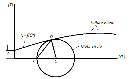
Fig.: Mohr’s Theory
Columb later modified Mohr’s equations and gave the following equation.
S=c+ 
∴Thus Mohr envelope is replaced by straight Line

Fig.: Mohr’s coulomb envelope
We can say that c is intercept on c axis and is angle made by envelope with  axis. The component 'c' of shear strength is called as cohesion which is independent of normal stress which hold soil particle together and d-represent angle of internal friction. Failure occurs when Mohr circle touches failure envelope or one can say at a maximum obliquin (Bmax) in which resultant touches Mohr circle and when
  and c gives a critical combination failure occurs.
Incase where c=0 the graph starts from origin and equation becomes.
S= 
In case where =0 i.e. friction less or fully cohesive soil the line will be horizontal. Later it will be found that c and depends upon number of factor like water content drainage conditions and lesting condition. Thus terzaghi shows that the effective stress control the shear strength and hence the equation gets modified
:. s = c’+tan
c' =Effective cohesion intercept
 Effective angle of shearing resistance
 = Effective stress
This above equation is called as Mohr Coulomb equation for shear strength of soil.
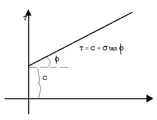
Fig.: Soil with internal friction and cohesion
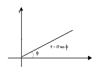
Fig.: Cohesionless soil
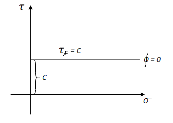
Fig.: Frictionless soil
Q5) Explain Direct test?
A5)
- This is the oldest shear test method in use and still most common because of its simplicity. It is also known as shear box test.
- The soil specimen is confined in a metal box that is split horizontally.
- If the specimen is fully or partially saturated, perforated metal plates and porous stones are placed above and below the specimen for drainage.
- If the specimen is dry, solid metal plates are used.
- A pressure pad is placed on top and the entire box is placed in a trolley.
- The upper half of the box is fixed to a support through a proving ring and the lower half of the box is pushed at a constant rate of strain. A vertical load is applied on the pressure pad. At time of failure, shear stress is measured by the proving ring.
- Then the test is repeated for another sample of the same soil, for a different vertical load on the pressure pad.
- 4-5 repeatitions are made for 4-5 different normal loads. By dividing normal load and corresponding shear load at failure by the internal horizontal area of the shear box, the normal and shear stress values can be obtained.
- These values are plotted and a best fit straight line through these points gives the strength envelope. From this C and
 can be determined.
 - The arrangement is shown in Fig.

Fig.: Test arrangement
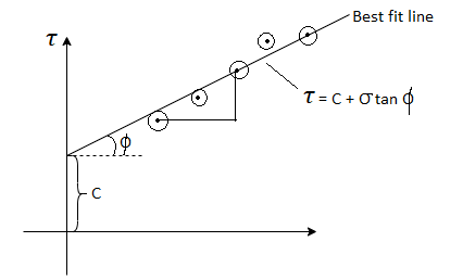
Fig.: Graph of direct shear test
Q6) Explain Advantages and Disadvantages of Direct Shear Test?
A6)
Advantages and Disadvantages of Direct Shear Test are as follows:
Advantages:
- Test is simple and fast.
- Drainage is quick due to less thickness of sample.
- CD and CU tests takes relatively small period, because of quick drainage and rapid dissipation of pore water pressure.
- Test is ideally suited for drained tests on cohesionless soils.
- The direct shear test apparatus is relatively cheap.
Disadvantages:
- Failure of soil specimen is always along a horizontal plane, which may not be very realistic.
- If any large soil particles or stones etc. are present at failure plane, it will give wrong results.
- Actual field condition is not simulated in the set up.
- Measurement of pore pressure is not possible.
Q7) Explain Triaxial test?
A7)
- A Casagrande invented the triaxial compression test so as to remove the disadvantages of the direct shear test. The triaxial compression test is most efficient and versatile of all the shearing testing methods of any type of soil. In this method, drainage condition can be controlled. Pore water pressure can be measured accurately and also volume changes can be measured with the help of triaxial test.
- Fig. Shows the triaxial cell in which the soil sample is subjected to confining pressure (
 ) by applying pressure to water in the cell. Note that there is no rotation of the principal stresses during the test and the failure plane is not forced. The soil sample can fail on any weak plane or can simply bulge. In short, the soil sample may subject to brittle failure or plastic failure.
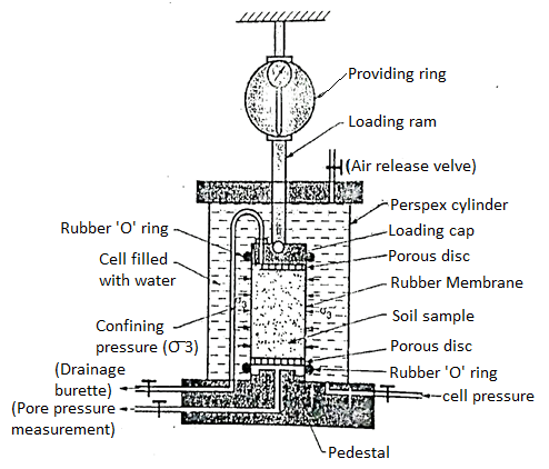
Fig.: Triaxial cell
- The triaxial test is carried out on a cylindrical sample er specimen of soil which is being taken securely in the rubber membrane. Cylindrical specimen of soil having a length to diameter ratio as 2. The usual sizes of specimen of soil are 76 x 38 mm or 100 x 50 mm.
- The traixal test apparatus consists of the following components:
- Loading frame
- Proving ring
- Pressure apparatus
- Loading arm
- Porous disc
- Triaxial cell
- Pressure chambers
- Sample trimmer
- Rubber 'O' ring
- Air release value
- Triaxial cell is a perspex cylinder which is attached to the base with rubber seals so as to make the cell water tight. The pressure cylinder controls the constant pressure in the triaxial cell. Sometime a separate compressor is used to apply fluid pressure in the cell. There is a separate pore pressure measg equipment which measure the pore pressure developed in the soil specimen during test. Cylindrical soil specimen is enclosed in a rubber membrane.
- A stainless-steel piston running through the centre of the top from which the vertical compressive load (deviator stress) can be applied on the soil specimen under test.
- Porous discs are placed on the top and bottom of the soil specimen and rubber membrane is sealed by rubber 'O' ring depending upon the drainage conditions of the test.
Test procedure:
Following are the various points which explains the test procedure.
- The cylindrical specimen is kept on a saturated porous disc resting on the pedestal of the triaxial cell.
- The cylindrical specimen is enclosed by a rubber membrane and sealed at the top and bottom by rubber 'O' ring. The rubber membrane prevents the penetration of water into the soil specimen.
- The triaxial cell is filled with water at the required pressure through cell pressure unit. This water pressure is subjected to the soil specimen to all-around. This water pressure is called as cell pressure or the confining pressure (
 )). Cell pressure acts radially on the vertical surface of the specimen and axially at the top and bottom.
 - By keeping constant cell pressure, additional axial stress is applied through the ram gradually until the soil specimen fails. This t additional axial stress is also called as deviator stress produces shear stresses within the soil sample on all planes except the horizontal and vertical planes.
Fig. Shows the principal stresses on the triaxial specimen
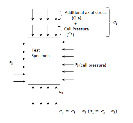
Fig.: Principal stress on the triaxial specimen
In the first stage, cell pressure ( )) is applied on the test specimen and in the second stage, deviator stress (ie. Additional axial stress,
  ) is applied on the sample until the failure of the soil specimen.
 =deviator stress (
 )+cell pressure (
 )
)
 =
= -
-
5. During triaxial loading, outlet valve of drainage burette is kept open so as to have the result for drained loading. This outlet valve is kept closed for an undrained loading.
6. The drainage burette or drainage outlet is connected to the pore pressure apparatus by which pore pressure can be measured.
7. The drainage burette is also connected to the volume measuring apparatus so as to measure change in volume for drained loading.
Q8) What are the advantages and disadvantages of Triaxial test?
A8)
Advantages of Triaxial Test:
Following is the various advantage of triaxial test
- A Casagrade developed the triaxial test in his research and removed the disadvantages of direct shear test.
- There is a complete control during conducting the shear test under all the three drainage conditions.
- Porewater pressure and volume change are precisely measured during the test.
- There is uniform stress distribution on the failure plane.
- State of stress within the soil sample during any stage of the test and at the failure of soil sample is completely determinate.
Disadvantages of Triaxial Test:
- The apparatus in triaxial test is bulky, costly and elaborate.
- Triaxial test takes longer period in case of drained test as compared with that in a direct shear test.
Q9) Explain Unconfined Compression test?
A9)
- This test is especially useful for homogenous cohesive clayey soils. It cannot be used for dry.
- In this test, a cylindrical soil specimen is fitted between two plates, with slight conical projections for firm grip on the specimen, and a compressive axial stress is applied on it till it fails.
- Since the test is quick, water is not allowed to drain out from the specimen, hence it is an undrained test. If qu, is the stress at failure, then the shear strength is given as,
 f=Cu=qu/2
- The arrangement is shown in Fig. The Mohr's circle in this case is drawn and the various parameters are shown.
- Internal friction is assumed to be zero as this test can be used only for purely cohesive soils.
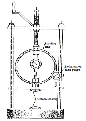
Fig.: Test arrangement
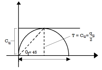
Fig.: Mohr’s circle
Advantages of Unconfined Compression Test:
- It is quick and convenient for meaning shear strength.
- It is useful for homogeneous cohesive clayey soil.
- It is suitable for measuring unconsolidated, undrained shear strength of saturated class
- It is used to measure insitu strength and very useful for field test.
Disadvantages of Unconfined Compression Test:
- This test cannot be carried out on coarse grained soils like sands and gravels and also not carried out on fissured clays.
- The test result may be misleading for the soils for which
 0.
0.
Q10) Explain Drainage conditions?
A10)
There are three types of drainage conditions for shear tests as explained follows:
Consolidated-undrained conditions (CU condition):
- Before shear, the specimen or soil sample is allowed to consolidate and the drainage is allowed until the consolidation is completed in first stage.
- During shear, no drainage is allowed or drainage is stopped in second stage this test is also termed as CU test or 'R' test.
Consolidated drained conditions (CD condition):
- Before shear, the specimen is allowed to consolidate during drainage conditions in first stage.
- During shear; drainage is allowed in second stage. Note that rate of shearing is kept very low to ensure that a fully drained condition exists such that excess pore water is zero.
- This test is also termed as CD test.
Unconsolidated-undrained condition (UU condition):
- Before and after shear, no drainage and consolidation is allowed; that means before application of axial stress or shear in first stage, drainage and consolidation is not allowed and after shear or application of axial stress, no drainage and consolidation of soil sample is permitted in second stage of test.
- Due to unconsolidated and undrained condition, the test can be carried out quickly in a less time and therefore this test is also called as 'quick test' or 'UU test'.
Q11) Explain Vane Shear tests?
A11)
- This is a test preferred when shear strength of soil in the undisturbed state is required.
- For some soils, it is very difficult to get undisturbed sample. In that case, the field vane shear test is very useful.
- In this test, a shaft to which 4 vanes are welded is slowly penetrated in the ground (in an undisturbed large sample brought to the laboratory) and by turning the shaft slowly, the torque required for failure of soil is measured.
- At the time of failure, a cylindrical portion of soil is sheared off from rest of the soil mass.

Fig.: Vane shear test
- By using following formula, shear strength Tf can be found out.
 =
=
- When the vanes penetrate well below the top surface of the soil, or,
 =
=
- When the vanes are flush with the top surface of soil.
Where, = shear strength,
T = torque applied,
H =height of vanes,
d =diameter of circle formed on rotating vanes.
The arrangement is shown in Fig.
Plotting Strength Envelope:
- In all the shear tests, plotting of strength envelopes is done with the help of Mohr's circle. Two or more samples must be tested for drawing the strength envelope.
- Only in unconfined test, only one Mohr's circle is drawn and a horizontal tangent to it gives strength envelope.
- In case of other tests, two or more Mohr's circles corresponding to the results are drawn and a best-fit common tangent to these circles, gives the strength envelope.
Determining Shear Strength Parameters of Soil:
- The cohesion 'C' measured in N/mm² and the angle o are called the parameters of the shear strength Tf measured in N/mm². As shown in Fig.after plotting any test results, the shear strength parameters C and
 can be directly measured from the graph.
 - In case of direct and triaxial tests (triaxial test is not in the syllabus), C and
 can be determined without plotting the values simply by solving simultaneous equations generated by putting different values of
  and
and  in the equation
  =c+
=c+ 
Q12) What is Stability of slopes?
A12)
- Stability of slopes plays an important role in the earth embankments or in cuttings required for railways roadways, earthen dams, river training , levees, highways Slopes may be artificial or may also natural as in Hillside and valleys, coastal, river clifts etc. Hence in case of slopes may be artificial or natural, the force exist which tend to cause the soil to move from high points to low points.
- If actual movement of soil mass occurs, it is a slop failure Force of gravity and seepage force are mainly responsible to cause the instability of Lipes in the areas of seismic activity, the earthquake forces is also an important factor causing instability of slope.
- Stability analysis is made commonly by using a Lit equilibrium approach. In this method, the shearing resistance required to maintain a limiting equilibrium condition is compared with the available shearing strength of the soil.
Actuating force
- The forces causing the instability induces the shearing stresses throughout the soil muss is termed as actuating force. Gravity force, seepage force and earthquake force are actuating forces.
Slip surface
- The surface along which the failure occurs in the form of mass movement of soil due to larger shearing stress is called as slip surface.
- Analysis of stability of slopes requires the determination of the actuating forces such a gravity forces, seepage forces and earthquake forces.
Q13) Explain the classification of slopes?
A13)
Slopes are classified as follows:
- Infinite slopes
- Finite slopes
- Homogeneous slopes
- Non-homogeneous slopes
- Slopes can be a natural slopes or man-made slopes. When the stope are formed with a continuous process of erosion and deposition of soil caused by natural agencies, then it is called as natural slopes.
- Examples of natural slopes: River banks, hill sides or mountain sides are the examples of natural slopes.
- When the slope of earth structures is made by or constructed by human, then it is called as manmade slopes.
- Example of man-made slopes: Slopes of embankment of dam, canals, roads, highways, railways, cutting for roads and rails, filling for reclamation trench excavations etc are the examples of manmade slopes.
1. Infinite slope:
- The boundary surface of a semi-infinite soil mass having the constant soil properties for all identical depths below the surface is called as infinite slope.
- The Fig. Shows a infinite slope with its traverse extent large as compared to the depth of its failure zone.
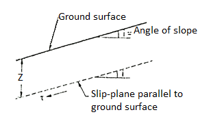
Fig: An infinite slope
- Slopes extending to infinity do not exist in nature.
2. Finite slopes:
- When the slope is having the limited extent, then it is called as finite slopes. Most man-made embankments and road or railway, cuts etc. are finite in extent.
- Examples of finite slopes: Inclined faces of earth dam, embankments, cuts etc are the examples of finite slopes.
- Fig. Shows the finite slopes.
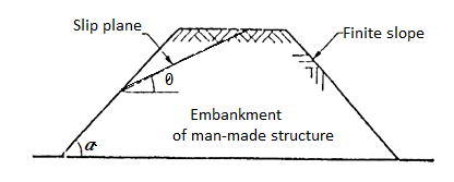
Fig.: Embankment
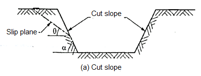
Fig.: Cut slope
3. Homogeneous slopes:
- When the slopes are made up of same material: I more or less within the failure zone, then it is termed as homogeneous slopes.
4. Non-Homogenous slopes:
- When the slopes are made up of different earth material or when the failure surface goes through two or more zones of different soil properties, then it is termed as non-homogenous slopes.
Q14) What is slope failure?
A14)
- When the failure occurs along a surface of sliding interests the slope above the toe, then slide is termed as slope failure or face failure.
- This type of failure occurs due to very high slope angle (i) and soil close to the toe is quite strong or the soil the upper part of the slope is comparatively weak.
- Fig. Shows plane slide and rotational slide respectively in case of slope failure, face failure.
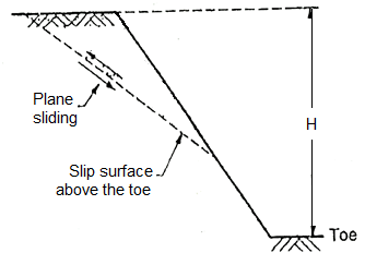
Fig.: Plane side of Face failure
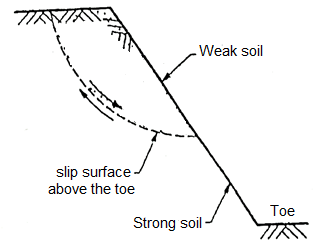
Fig.: Rotational side of face failure
Q15) What is Base failure?
A15)
When the failure surface passes below the toe of slope, then it is termed as base failure. This type of failure occurs due to the weaker material or relatively weak and soft soil at the base than that of slope. Fig. Shows the base failure.

Fig.: Modes of base failure
Q16) What is Toe failure?
A16)
- When the failure surface passes through the toe of slope, then it is termed as toe failure. Toe failure is most common mode of failure and occurs in steep slope consisting of the homogeneous solid mass above and below the base.
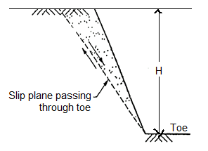
Fig.: Plane side of Toe failure

Fig.: Rotational side of toe failure
Q17) What is Swedish circle method?
A17)
- The Swedish Slip Circle approach assumes that the friction perspective of the soil or rock is same to zero, i.e., tau =c.
- In different words, while friction perspective is taken into consideration to be zero, the powerful strain time period is going to zero, hence equating the shear power to the brotherly love parameter of the given soil.
- The Swedish slip circle approach assumes a round failure interface, and analyzes strain and power parameters the use of round geometry and statics.
- The second due to the inner riding forces of a slope is as compared to the instant due to forces resisting slope failure.
- If resisting forces are more than riding forces, the slope is thought stable.
Q18) What is Friction Circle method?
A18)
- The balance of earth slopes in keeping with the friction circle approach, as generally employed, is primarily based totally at the circumstance of equilibrium of forces, and at the circumstance that at restriction equilibrium the actuating and resisting forces are concurrent at one factor. This specific circumstance, assumed in area of the overall one in all equilibrium of moments on the stated balance restriction, isn't according with the essential hypotheses of the kinematics of motion; it offers upward thrust as nicely to the indetermination of the couple of values of the soil resistance parameters c (cohesion) and ϕ (friction) at restriction equilibrium.
- Therefore the trouble is taken up once more and resolved on the premise of rational equilibrium situations and assuming that at failure in any factor alongside the sliding circle the maximal electricity of the cloth is evolved and consequently restriction values of c and ϕ right to failure of the specific soil are uniformly reached alongside the circle itself.
- On this foundation the circumstance of equilibrium of forces determines one parameter of the distribution sample of the everyday additives of stresses alongside the circle; the price of a 2d parameter of the stated distribution, concerned withinside the circumstance of equilibrium of moments, may be without problems decided in an approximate way.
- It is consequently viable to decide without problems and swiftly the arm of the whole actuating pressure which realizes the restriction circumstance of the intended sliding motion alongside the taken into consideration circle. The contrast of this arm with the actual one of the aforesaid pressure suggests the diploma of balance for any taken into consideration circle.
- The extension of the approach to an embankment made of zones of various substances is likewise examined.
Q19) What is Taylor’s Stability Number and Stability Charts?
A19)
- The slipping along the slip are at critical equilibrium is resisted by the total cohesive force (CL). This force is proportional to the cohesion C and the height H of the slope.
- The force responsible for instability of i se slope is the weight of the wedge which is equal to the unit weight
 .
.
∴Weight of the wedge  H2
H2
- Let (F.S)c be the factored of safety for cohesion.
We know,
=
= =Sn ….(1)
- Here
 is the dimensionless quantity which is called as Tayler's stability number (Sn).
 - Consider Cm be mobilised unit cohesion which is essential so as to have the equilibrium of a slope having height H.
Cm= …(2)
…(2)
Where C= Cohesion:
(F.S)c= Factor of safety with respect to cohesion
Hence the Equation (1) can be written as follows:
Sn = =
= ….(3)
….(3)
- Also, for critical height H the factor of safety with respect to height (H) is equal to the factor of safety with respect to cohesion (C)
∴(F.C)c =Hc/H…(4)
Where (F.C)c = Factor of safety with respect to cobesion
There Equation (3) becomes as
Sn = =
= …(5)
…(5)
- Taylor analysed the friction circle method and determined the values of stability number (Sn) for finite slopes and prepared the table as shown in Table gives the values of Sn for the various values of and slope angle (i).
- When a dangerous circle passing below the toe occurs, then stability numbers such as (0.145). (0.068) and (0.023) mentioned in Table indicates the most dangerous circle through toe.
- The Fig. Shows Taylor's stability number charts for
 =0
=0
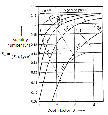
Fig.: Taylor’s stability number charts, =0 with respect to depth factor
Q20) What are the Principle stresses?
A20)
- There are two principal stresses like major and minor principal stresses are to be considered and third principal stress in the third direction is not much relevance.
- Major principal stress (
 1): The normal stress without shear stress acting on the major principal plane is called as major principal stress (
 ).
). - Minor principal stress (
 ): the normal stress without shear stress acting on the minor principal plane is called as minor principal stress (
 .
. - The intermediate principal stress (
 ) is not much relevant, hence not considered in the many problems in geotechnical engineering, only major principal stress (
 ) and minor principal stress (
 ) are important.
 - Following equation shows the equation of circle,
 +
+ 2 =
2 = 2
2
Where,  = Normal stress
 = Shear stress
 1= Major principal stress
 = Minor principal stress
The co-ordinates of centre of circle are  =0 and
 =
= and its radius is