Unit - 1
Highway Development & Planning
Q1) Discuss the Optimum Road Length using Lucknow Road Plan.
A1)
Optimum Road Length using Lucknow Road Plan
- Length of NH = Area (km2)/50
- Length of SH = maximum of
Area (km2)/25
OR
(62.5 x number of towns) – Length of NH
3. Length of MDR = maximum of
Area (km2)/12.5
OR
90 x number of towns
4. Total Road Length = 4.74 x number of towns x number of villages
5. Length of (ODR + VR) = Total Road Length – Length of (NH + SH + MDR)
6. If number of towns/ villages are not given,
Total Road Length = Road Density x Area where,
Road Density = 82 km/ 100 km2 and Area is in km2
Q2) Discuss the Optimum Road Length using Nagpur Road Plan.
A2)
NH + SH + MDR = [ + D – R
ODR + VR = [0.32V + 0.8Q + 1.6P + 3.2S] + D
Here, NH = National Highway
SH = State Highway
MDR = Major District Roads
ODR = Other District Roads
VR = Village Roads
A = agricultural area, km2
B = non-agricultural area, km2
N = number of towns & villages with population range 2001-5000
T = number of towns & villages with population > 5000
D = development allowance of 15% for next 20 years
R = existing length of railway track
V = number of villages with population 500 or less
Q = number of villages with population 501-1000
P = number of villages with population 1001-2000
S = number of villages with population 2001-5000
Q3) Discuss the Optimum Road Length using Bombay Road Plan.
A3)
NH = [ + [32K + 8M] + D
NH + SH = [ + [48K + 24M + 11.2N + 1.6P] + D
NH + SH + MDR = [ + [48K + 24M + 11.2N + 9.6P + 4.6Q + 2.4R] + D
NH + SH + MDR + ODR = [ + [48K + 24M + 11.2N + 9.6P + 4.6Q + 2.4R] + D
NH + SH + MDR + ODR + VR = [ + [48K + 24M + 11.2N + 9.6P + 12.8Q + 5.9R + 1.6S + 0.64T + 0.2V] + D
Here, NH = National Highway
SH = State Highway
MDR = Major District Roads
ODR = Other District Roads
VR = Village Roads
A = developed & agricultural area, km2
B = semi-developed area, km2
C = undeveloped area, km2
K = number of towns with population > 100000
M = number of towns with population 50000 - 100000
N = number of towns with population 20000 - 50000
P = number of towns with population 10000 - 20000
Q = number of towns with population 5000 - 10000
R = number of towns with population 2000 - 5000
S = number of towns with population 1000 - 2000
T = number of towns with population 500 - 1000
V = number of towns with population 500 or less
D = development allowance of 5% for next 20 years
Q4) Discuss the Optimum Road Length using Maximum Utility System.
A4)
Maximum Utility System for Optimum Road Length
Various studies are made to assess the road length requirements, including economic studies, financial studies, traffic or road use studies and engineering studies.
However, one of the most commonly used method for deciding the Optimum Road Length is the Maximum Utility System. In this system, the optimum road length for an area is calculated on the basis of maximum utility per unit length of the road. This system is also known as Saturation System. Factors for obtaining the utility per unit length of road are:
- Population served by the road
- Agricultural & Industrial productivity served by the road network
A utility unit is assigned to towns/ villages on the basis of population, as given in the table below:
Population | Utility Unit |
< 500 | 0.25 |
501 - 1000 | 0.50 |
1001 - 2000 | 1.00 |
2001 - 5000 | 2.00 |
This is followed by phasing of the road development plan by fixing the priorities for construction of different road links.
Q5) Discuss the Order of Road Development and state the features of different road types.
A5)
Order of Road Development
- Roman Roads (312 B.C.)
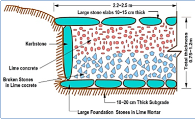
- These roads were built straight regardless of gradients.
- Total thickness = 0.75 – 1.2 metres
- Top or wearing course was made up of large stone blocks set in lime mortar.
Ii. Tresaguet Construction (1764 A.D.)
- Drainage of water & subgrade moisture was given due consideration.
- Top or wearing course had a cross-slope of 1 in 45 while shoulder sloping was 1 in 30.
- Total thickness = 0.3 metres
Iii. Metcalf Construction (1717-1810 A.D.)
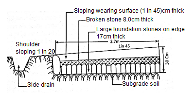
- Drainage of water & subgrade moisture was given due consideration.
- Top or wearing course had a cross-slope of 1 in 45 while shoulder sloping was 1 in 30.
- Total thickness = 0.3 metres
Iv. Telford Construction (1751-1834 A.D.)
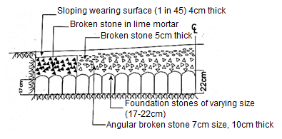
- Subgrade was horizontal and drainage was not considered.
- Thickness of foundation stone varied from 17 cm at edges to 22 cm at the centre.
- Wearing course of 4 cm thickness was provided with a cross slope of 1 in 45.
v. Macadam Construction (1827 A.D.)
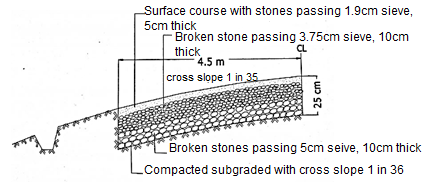
- First method based on scientific thinking.
- Macadam provided stones of size less than 5 cm to a uniform thickness of 10 cm for foundation.
- Sub-grade drainage was given consideration and hence, cross slope of 1 in 36 was provided.
Vi. Water Bound Macadam (W.B.M.)
- Broken stones of the base course and surface course are bound by stone dust in presence of moisture.
- Total Thickness = 8-30 cm
- Cross slope = 1 in 36 to 1 in 48
Q6) Briefly state the projects under NHDP.
A6)
The National Highways Development Project (NHDP) is a project to upgrade, rehabilitate and widen major highways in India to a higher standard. The project was started in 1998 under the leadership of former Prime Minister, Atal Bihari Vajpayee. National Highways account for only about 2% of the total length of roads, but carry about 40% of the total traffic across the length and breadth of the country. This project is managed by the National Highways Authority of India (NHAI) under the Ministry of Road, Transport and Highways.
Projects under NHDP (Phase 1 to Phase 7)
a) Golden Quadrilateral
GQ connects the four major cities of Delhi, Mumbai, Chennai and Kolkata. This project connecting four metro cities is 5,846 km in length.
b) North South Corridor & East West Corridor
N-S corridor connects Srinagar in the north to Kanyakumari in the south, while E-W corridor connects Silchar in the east to Porbandar in the west. Total length of the network is 7,142 km.
c) Improvements to city road networks by adding ring roads to enable easier connectivity with national highways to important cities.
Q7) Explain highway alignment and project preparation.
A7)
Engineering Surveys for Highway Alignment
The following steps are involved in finalizing the Highway alignment & preparing the project:
a) Map Study:
- It is the very first step of highway survey.
- In this, we use a topographic map of the area under consideration, which can be availed from the Survey of India. Using the map, we can propose different alternatives of the road alignment.
- The topographic map usually has contour intervals of around 30 m to 40 m.
- We can get the details of the natural as well as man-made land features of the area using this map, and based on this we can then suggest a number of options for the road alignment.
- These alternative route options are further studied in detail in the later steps.
b) Reconnaissance Survey:
- This is done to examine the general character of the area for deciding the most feasible routes for detailed studies.
- Basic surveying instruments are used in the reconnaissance survey.
- Following data is obtained from Reconnaissance Survey:
Valley, pond, lakes and other features that may not be present on the topographical map.
A number of cross drainage structures, High Flood Level (HFL), Natural Ground Level etc.
Values of the gradient, the length of gradients and radius of the circular curve.
Soil type along the routes from field identification tests and observation of the geological features.
Sources of construction materials.
c) Preliminary Survey:
This is carried out to collect all the physical information which is necessary in connection with the proposed highway alignment. This work consists of:
- Primary traverse survey
- Study of topographical features
- Leveling work
- Drainage studies & hydrological data
- Soil survey
- Material survey
- Determination of final centre line
This may be done using:
- Conventional Approach: This includes using conventional survey instruments.
- Modern Rapid Approach: This is done by aerial photography.
d) Final Location & Detailed Survey:
- Final Location: The centre line of the road which is finalized in the preliminary survey is located in the field by establishing the centre line. Major and minor control points are set on the ground and the central pegs are driven.
- Detailed Survey: Temporary Bench Marks (TBMs) are fixed and leveling work is done for vertical alignment, earthwork calculation and drainage details.
Q8) What are the various road patterns adopted in India?
A8)
A road network can be laid in various patterns. These are discussed as follows:
a) Rectangular or Block Pattern:
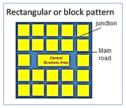
- The whole area is divided into rectangular blocks of plots, with streets intersecting at right angles.
- The main road which passes through the center of the area should be sufficiently wide and other branch roads may be comparatively narrow.
- The main road is provided a direct approach to outside the city.
Advantages:
The rectangular plots may be further divided into small rectangular blocks for construction of buildings placed back to back, having roads on their front.
In this pattern has been adopted for the city roads.
The construction and maintenance of roads of this pattern is comparatively easier.
Limitations:
This pattern is not very much convenient because at the intersections, the vehicles face each other.
b) Radial or Star and Block Pattern:
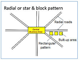
- The entire area is divided into a network of roads radiating from the business outwardly.
- In between radiating main roads, the built-up area may be planned with rectangular block.
Advantages:
Reduces level of congestion at the primary bottleneck location.
Prevents traffic from accessing local flow routes in the direction of the event venue that operate in favor of egress traffic flow.
If one is block then other side traffic can move.
Vehicles face each other less than block pattern.
Limitations:
Proves particularly effective if two-lane ramp traffic does not have to merge at downstream end of ramp.
Safety appurtenances such as guide rail transitions, crash attenuators, and post support bases have not been designed to provide adequate protection at hazardous locations from the opposite direction of travel.
c) Radial or Star and Circular Pattern:
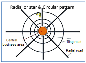
- Radial network of road radiates from the centre outwardly.
- Main radial streets are connected by concentric rings.
Advantages:
Safer as vehicles travel in the same direction.
Reduces possibility of crashes.
Roundabouts improve flow efficiency and reduce fuel consumption.
Limitations:
Providing a good curve is difficult.
Traffic signs, pavement markings, and lighting should be adequate so that drivers are aware that they should reduce their travel speed while approaching the roundabout.
Islands separating the approach and exit lanes, known as splitter islands, should extend far enough.
d) Radial or Star and Grid Pattern:
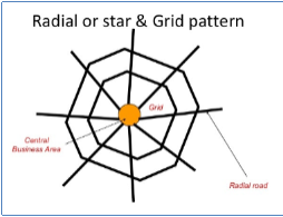
- Radial network of road radiates from the centre outwardly.
- Main radial streets are connected by providing a grid pattern.
Advantages:
Improves traffic flow.
Reduce cut-through traffic.
Improve land use efficiency and unit density.
Limitations:
Islands separating the approach and exit lanes, known as splitter islands, should extend far enough.
Traffic signs, pavement markings, and lighting should be adequate so that drivers are aware that they should reduce their travel speed.
e) Hexagonal Pattern:
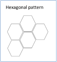
- In this pattern, the entire area is provided with a network of roads formatting hexagonal figures.
- At each corner of the hexagon, three roads meet the built-up area boundary by the sides of the hexagons is further divided in suitable sizes.
Advantages:
Three roads meet the built-up area boundary by the sides of the hexagons.
Limitations:
Traffic signs, pavement markings, and lighting should be adequate so that drivers are aware that they should reduce their travel speed.
f) Minimum Travel Pattern:
- In this road pattern, city is connected to suburban centre and neighbourhood centre by the short, straight roads.
Advantages:
These types of potentially serious crashes essentially are eliminated.
Limitations:
Traffic signs, pavement markings, and lighting should be adequate so that drivers are aware that they should reduce their travel speed.
Intersections can be especially challenging for older drivers.
Q9) What are the types of failures that can occur in a Cement Concrete Pavement?
A9)
The types of failures that may occur in a cement concrete pavement are, as follows:
Cracking of corner slabs
Longitudinal cracking of pavements
Settlement of slabs
Widening of Joints
Mud pumping: ejection of soil slurry through the joints & cracks
The causes of failures are, as follows:
Deficiency in pavement materials
Creep
Structural Inadequacy
Q10) Discuss about Reinforced Concrete Pavements.
A10)
Reinforcement used in cement concrete pavements is in the form of welded wire fabric or bar mats. The function of reinforcement is to hold the cracked slab portions together and thus not allow them to open up any more. It does not provide any additional flexural strength.
It is suggested that greater quantity of reinforcement should be placed in longitudinal direction and should be placed in the mid-depth or towards the top of the pavement for better functioning.
Reinforcement Requirements:
For moderate traffic = 3.5 kg/m2
For heavy traffic = 7.0 kg/m2
Q11) Classify roads.
A11)
Classification of Roads
- Primary, secondary & tertiary road system
Primary: Expressways & National Highways (NH)
Secondary: State Highways (SH) & Major District Roads (MDR)
Tertiary: Other District Roads (ODR) & Village Roads (VR)
2. On the basis of usage during different seasons
All-weather Roads: negotiable during all weathers
Fair-weather Roads: negotiable during all weathers except monsoon season where streams may overflow across the road
3. On the basis of road pavement
Paved Roads: provided with hard pavement surface which should be at least a Water Bound Macadam
Unpaved Roads: earth roads and gravel roads
4. On the basis of pavement surfacing
Surface Roads: provided with bituminous or cement concrete surfacing
Un-surfaced Roads: not provided with bituminous or cement concrete surfacing
5. Classification of rural & urban roads
Rural Roads: classified on the following basis –
a) Traffic Volume – Heavy, medium or light
b) Load Transport – Class A, Class B etc
c) Location & Function
Urban Roads: classified into the following types –
a) Arterial Roads
b) Sub-arterial Roads
c) Collector Streets
d) Local Streets
Q12) Explain Current Road Projects in India.
A12)
Indian road network is the third largest road network in the world, after United States and European Union. A road network consists of urban roads and rural roads including expressways, highways, bridges, local roads, arterial roads etc.
As we have seen and heard lately, these expressways are the highest class of road in India. These are well-equipped with latest technologies like CCTVs, temperature and speed measurement equipments, SOS booths, restaurants, washrooms etc. Currently, the Yamuna Expressway connecting Delhi to Agra is the longest 6-lane controlled-access expressway highway in India.
Some of the current & upcoming important road projects in India are discussed as follows:
- Bharatmala Project
- NHDP-funded with a focus on optimizing the efficiency of freight and passenger movement across the country
- Includes development of National Corridors, Economic Corridors, Feeder Routes, Border Roads, International connectivity roads, Coastal and Port connectivity roads, expressways etc all across the country, with a total road length of 34,800 km.
- It is one of the important road projects in India and was announced by the Transport Minister himself, Shri Nitin Gadkari.
2. International North South Transport Corridor
- The International North–South Transport Corridor (INSTC) is the water, rail, and road route between India, Russia, Iran, Europe and Central Asia.
- The current INSTC project was initiated by Russia, India and Iran in September 2000 in St. Petersburg.
- It is a multi-modal transportation route that links Indian Ocean and Persian Gulf to the Caspian Sea via Iran, and then moves onward to northern Europe via St. Petersburg in Russia.
- The route primarily involves moving freight from India, Iran, Azerbaijan and Russia via ship, rail and road.
- The objective of the corridor is to increase trade connectivity between Mumbai, Tehran, Moscow, Baku, Astrakhan etc.
3. Char Dham Expressway
- Char Dham Expressway National Highway is a proposed two-lane (each direction) National Highway with a minimum width of 10 metres in the state of Uttarakhand.
- It will connect the four major holy places in India: Badrinath, Kedarnath, Gangotri and Yamunotri.
- The project includes 900 km of national highway that will connect the entire Uttarakhand state.
4. Ganga Expressway
- The Ganga Expressway is an eight-lane access controlled project with express highway of length 1,047 km along the Ganga River.
- The Project aims to connect Greater Noida to Ballia in Uttar Pradesh state via Varanasi, Allahabad, RaeBareli, Kanpur, Farrukhabad and Bulandshahr.
- The expressway will be equipped with all the possible facilities.
5. Delhi-Jaipur Expressway
- The Delhi-Jaipur Expressway is proposed six-lane expressway that connects Delhi to Jaipur via a 235 km long road length.
- It will run through the Rajasthan, Haryana and Delhi.
6. Outer Ring Road Expressway
- The Outer Ring Road Expressway of Hyderabad is an eight-lane controlled-access expressway that aims to connect NH 9, NH-7, and NH-4 with other state highways.
- The 158 km expressway is road encircling the Hyderabad City of Andhra Pradesh.
7. Mumbai Nashik Expressway
- The Mumbai Nashik Expressway is a 150 km long expressway that connects the financial capital of Mumbai to the holy city of Nashik.
- It is a major gateway that aims to connect Mumbai to the rest of the Indian cities.