Unit - 4
Electrical Machines
Q1) A 1200V 50Hz delta connected IM has a star connected slip ring rotor with phase transformation ratio of 3.6. The rotor resistance and standstill leakage reactance are 0.012 and 0.25 ohm per phase. Find the rotor current with slip ring shorted. The power factor at start with slip ring shorted.
A1) In this case the primary phase voltage is same as line voltage.
The rotor phase standstill voltage = 1200 x [1/3.6] = 333.3V
a) Rotor impedance/phase =  = 0.2503Ω
b) Rotor phase current at start = 333.3/0.2503=1331.8A
Power Factor = 0.012/0.2503=0.048 lagging
Q2) A rotor of 6-pole 50Hz IM is rotated by some means at 1000 rpm. Find i) Rotor voltage. Ii) rotor frequency iii) rotor slip.
A2) N=1000rpm
F=50Hz
The synchronous speed Ns=120f/P=120x50/6=1000rpm
i) Rotor voltage Er=sE
S=Ns-N/Ns x100 = {[1000-1000]/1000} x 100 = 0
Since, s=0 Er=0
Ii) Rotor Frequency fr=sfs
Since, s=0
fr=0
Iii) Rotor slip s=0
Q3) A star connected rotor of an IM has a standstill impedance of 0.2+j3 ohm per phase and the rheostat impedance per phase of 6+j2 ohm. The motor has induced emf of 80V. Find the rotor current at standstill with the rheostat in the circuit.
A3) For standstill condition
Voltage/Rotor phase= 80/ = 46.2V
Starter impedance/phase = 6.2+j5=7.96
Rotor current/phase= 46.2/7.96=5.8
p.f= cos 38.88=0.778
Q4) A 3-phase 50Hz 6-pole IM has full load slip of 2%. The rotor resistance and standstill rotor reactance per phase is 0.002 and 0.048 ohm. Find the ratio of maximum full load torque and the speed at which the maximum torque occurs.
A4) Ns=120f/P=120 x 50/6=1000rpm
Slip at max. Torque ( smT) = rotor resistance/standstill rotor reactance=0.002/0.048=0.042
Now the speed becomes = (1-0.042) x 1000=958rpm

 = 15.5 x 10⁻³
Q5) A 6-pole 50 Hz 3-phase IM develops a maximum torque of 158.7 N-m at 1335 rpm. The resistance of the star connected rotor is 0.2 ohm/phase. Calculate the value of resistance that must be inserted I series with each rotor phase to produce a starting torque equal to half the maximum torque.
A5) Ns=120f/P=120 x 50/6= 1000rpm
N=1335rpm
Slip corresponding to maximum torque = (1335-1000)/1335= 0.25
Maximum Torque Tmax = 
X2=R2/slip corresponding maximum torque = 0.2/0.25=0.8ohm
Let H= 
Tmax =  = H/(2x0.8)=0.625H
Let r be the external resistance introduced per phase in the rotor circuit
Tsh =  =
= =
= 
But it’s given that Tsh =  Tmax
Tmax
 =
= 
0.625r2-1.75r+0.025=0
r=0.02Ω
Above r is the required resistance aa per the given conditions.
Q6) The power input to a rotor of 440V, 50Hz, 6-pole, 3-phase, induction motor is 60kW. The rotor force is observed to make 80 alterations per minute. Calculate i) slip ii) rotor speed iii) rotor cu loss per phase?
A6) 80 alterations per minute=80/60 cycles per second=1.333Hz=sf
i)slip=1.333/50=0.027 P.u.=2.7%
Ii)Rotor speed N=(1-s) Ns=(1-0.027) x 1000=973.33rpm
Ns=120f/P=120 x 50/6=1000rpm
Iii)rotor cu loss/phase= =
= =0.54kW
Q7) The power input to a 3-phase induction motor is 80kW. The stator loss is total 1kW. Find the mechanical power developed and the rotor cu loss per phase if the slip is 3%?
A7) P2= stator input – stator losses=80-1=79kW
Pm=(1-s)P2==(1-0.03) x 79=76.63kW
Total rotor cu loss=sP2=0.03 x 79=2.37kW
Rotor cu loss per phase=2.37x1000/3=790W
Q8) The power input to a rotor of a 400V, 50hz,6-pole, 3-phaseinduction motor is 15kW. The slip is 4%. Calculate i) frequency of rotor current. i)rotor speed. Iii)rotor cu loss iv) rotor resistance/phase if rotor current is 50A?
A8) i) frequency of rotor current=sf=0.04 x 50=2Hz
Ii) Rotor speed N=(1-s) Ns=(1-0.04) x 1000=960rpm
Ns=120f/P=120 x 50/6=1000rpm
Iii) rotor cu loss=s x rotor input=0.04 x 15=0.6kW
Iv)rotor cu loss/phase=0.6 x 1000/3=200W
602R2=200
R2=0.055Ω
Q9) Explain speed control of separately excited dc motor?
A9) In Separately excited DC motor field windings are used to excite the field flux. Armature current is supplied to the rotor through brush and commutator. When the motor is excited by a field current if and armature current ia flows, the motor develops a back emf and a torque to balance the load torque at a particular speed. The current if is independent of ia. The armature current has no effect on te field current. The current if is less than ia.
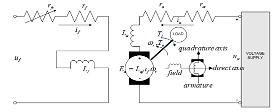
The speed can be controlled by varying voltage in the constant torque region. In the constant power region, field flux should be reduced to achieve speed above the rated speed.
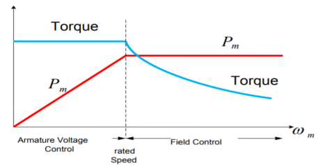
Fig: Armature voltage and field current control
Q10) Explain the working of IM?
A10) The fundamental principle of induction machine is the creation of rotating and sinusoidally distributed magnetic field in the air gap. Three phase balanced power supply is fed to the three-phase stator winding creates a synchronously rotating magnetic field. Due to relative speed between rotating flux and stationary conductors, an emf is induced. The frequency to induced emf is same as supply frequency.
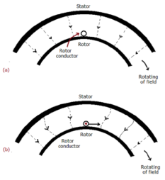
As shown in below fig. a, the stator field is assumed to clockwise. The relative motion of rotor w.r.t stator is anticlockwise. From Right-hand rule, the direction of induced emf in rotor is outwards. By the effect of combined field as shown in fig b the rotor experiences a force tending to rotate it in clockwise direction. Hence rotor rotates in the same direction as the stator field.
The speed of this rotating field is called synchronous speed. If the rotor is initially stationary, its conductors will be subjected to a changing magnetic field, inducing current in the short-circuited rotor at the same frequency. The interaction of air gap flux and rotor mmf produces torque. At synchronous speed rotor cannot have any torque.
Q11) Explain speed control of IM?
A11) The speed can be controlled by the following methods.
i) Changing stator Pole: This can be done by Multiple stator windings. In stator two windings are provided which are isolated and have different number of poles. By switching we can control the supply to one winding and hence control the speed.
Ii) Supply voltage control: The torque produced is proportional to  . The value of
  is very small and R2 is also constant so T α
 . But E2α V therefore, T α sV2. This equation shows that if supply voltage is decreased the torque also decreases.
Iii) Adding rheostat in the stator: As we already know Tα . The value of
  is very small and E2 is also constant soTα
 . Now if we increase rotor resistance, R2 torque decreases but to supply the same load torque must remain constant. So, we increase slip, which will further result in the decrease in rotor speed. Thus, by adding additional resistance in the rotor circuit, we can decrease the speed of the three-phase induction motor.
Iv) v/f control: There is no direct relation in the speed and torque. At, full load the motor runs at a speed N. When mechanical load increases motor speed decreases till the motor torque again becomes equal to the load torque.
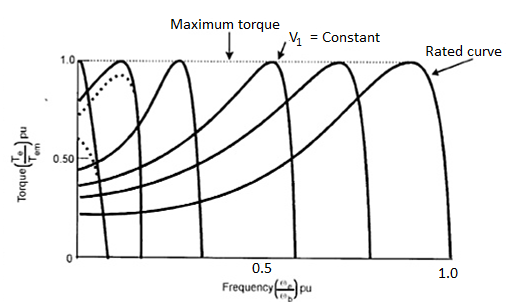
As long as two torques are equal the motor runs at constant speed. When the supply frequency increases the speed increases and reduces the maximum torque of motor. So,
i) F increases, N increases, Tmax decreases.
Ii) V increases, Tmax increases.
Q12) Explain DOL starter and list its advantages?
A)12 In this induction motor is directly connected to the 3-phase supply. The DOL starter applies full line voltage to the motor terminals.
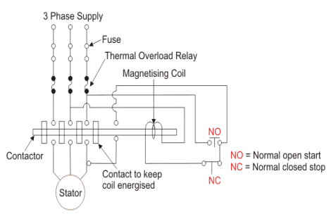
Fig: D.O.L Starter
If the high input current does not cause any excess voltage drop in circuit than only this starter can be used. The value of armature current in motor is given as
Ia=
The expression for starting torque is given as
Ts starting torque
Tf Full load torque
If per phase rotor current at full load
Is per phase rotor current at starting
sf full load slip
ss starting slip
R2 rotor resistance
Ws synchronous speed of motor
In induction motor torque is given as
T=
The ratio of starting torque to full load torque is given as
 x sf
x sf
The wiring diagram for a DOL starter is shown above. The working principle of a DOL starter begins with the connection to the 3-phase main with the motor. The control circuit is connected to any two phases and energized from them only. When we press the start button, the current flows through magnetizing coil and control circuit also.
The current energises the contactor coil and leads to close the contacts, and hence 3-phase supply becomes available to the motor. When we stop it, the current discontinues. As the supply to motor breaks the machine stops. . The contactor coil (Magnetizing Coil) gets supply even though we release start button because when we release start button, it will get supply from the primary contacts as illustrated in the diagram of the Direct Online Starter.
The advantages of a DOL starter include:
- Simple and most economical starter.
- More comfortable to design, operate and control.
- Provides nearly full starting torque at starting.
- Easy to understand and troubleshoot.
- DOL starter connects the supply to the delta winding of the motor.
Q13) Why 1-phase induction motor can be self started? Explain its working in detail?
A13) A Single-Phase Induction Motor consists of a single-phase winding which is mounted on the stator of the motor and a cage winding placed on the rotor. A pulsating magnetic field is produced, when the stator winding of the single-phase induction motor shown below is energized by a single-phase supply.
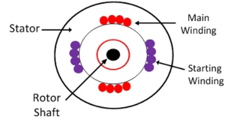
Fig: 1-phase IM
The word Pulsating means that the field builds up in one direction falls to zero and then builds up in the opposite direction. Under these conditions, the rotor of an induction motor does not rotate. Hence, a single-phase induction motor is not self-starting. It requires some special starting means.
If the 1 phase stator winding is excited and the rotor of the motor is rotated by an auxiliary means and the starting device is then removed, the motor continues to rotate in the direction in which it is started.
The performance of the single-phase induction motor is analysed by the two theories. One is known as the Double Revolving Field Theory, and the other is Cross Field Theory. Both the theories are similar and explain the reason to produce torque when the rotor is rotating.
Working of 1-phase IM
Double Revolving Field Theory of Single- Phase Induction Motor
The double revolving field theory of a single- phase induction motor states that a pulsating magnetic field is resolved into two rotating magnetic fields. They are equal in magnitude but opposite in directions. The induction motor responds to each of the magnetic fields separately. The net torque in the motor is equal to the sum of the torque due to each of the two magnetic fields.
The equation for an alternating magnetic field is given as
b(α) = β max sin w t cos α -----------------------(1)
Where βmax is the maximum value of the sinusoidally distributed air gap flux density produced by a properly distributed stator winding carrying an alternating current of the frequency ω, and α is the space displacement angle measured from the axis of the stator winding.
SinA cosB = ½ sin(A-B) + ½ sin(A+B)
So, the equation (1) becomes
b(α) =1/2 β max sin (w t- α) + ½ β max sin (w t+ α) ------------(2)
The first term of the right-hand side of the equation (2) represents the revolving field moving in the positive α direction. It is known as a Forward Rotating field. Similarly, the second term shows the revolving field moving in the negative α direction and is known as the Backward Rotating field.
The direction in which the single -phase motor is started initially is known as the positive direction. Both the revolving field rotates at the synchronous speed. ωs = 2πf in the opposite direction. Thus, the pulsating magnetic field is resolved into two rotating magnetic fields. Both are equal in magnitude and opposite in direction but at the same frequency.
At the standstill condition, the induced voltages are equal and opposite as a result; the two torques are also equal and opposite. Thus, the net torque is zero and, therefore, a single- phase induction motor has no starting torque.
Q14) A 230 volt 50 HZ, 4 pole single-phase induction motor has the following equivalent circuit impedances.

Friction windage and core loss =40W
For a slip of 0.03 pu, calculate
a) Input current
b) Power factor
c) Developed power
d) Output power
e) Efficiency
A14)


For the forward field circuit


For the backward field circuit


a) Input current 

b) Power factor=Cos(-60.95°)=0.4856 lagging
c) Developed power 

=479.65W
d) Output power=
=479.65-40=439.65 watt
Input power= 
=230×5.685×0.4856
=6349W
e) Efficiency=


Q15) A 230 volt 50 HZ, 4 pole single-phase induction motor has the following equivalent circuit parameters  Friction and windage, core losses are 50 Watt and slip is 0.025. Calculate
a) input current
b) power factor
c) developed power
d) output power
e) efficiency
A15)


For the forward field


For the backward field


a) Input current=

b) Power factor=cos(-66.0865)
=0.4053 lagging
c) Developed power 

=347.49 watt
d) Output power= 


Input power=VI


e) Efficiency= 

=56.17%
Q16) Compare single phase induction motor and three phase induction motor.
A16)
Single phase induction motors are constructed in fractional kilowatt capacity and are used in places where three phase supply is not readily available.
Sr. No | Single phase induction motor | Three phase induction motor |
1 | Single phase induction motor develops about 50% of the output of that of three phase Motors for the same size and temperature rise. | Output of three phase induction motor is more compare two single phase induction motor for the same size and temperature rise |
2 | Single phase induction motor have lower power factor | Better power factor |
3 | The starting torque is low in single phase induction motor | Starting torque is high, Also maximum torque can be obtained at starting condition |
4 | Single phase Motors are costly than 3 phase Motors of the same rating | Less costly |
5 | They are generally available up to 1 kW rating. | They are available up to 50000 kW |
Q17) A 3-phase, 50Hz, 8 pole alternator has a star connected winding with 120 slots, and 8 conductors per slot. The flux per Pole is 0.05 WB. Sinusoidally distributed. Determine the phase and line voltages.
A17)
The full pitch coil


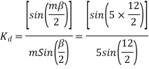
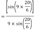
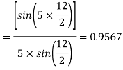
=0.9567
Total number of conductors=conductor per slot × number of slots
Z=8×120=960
Conductors per phase 

Generated voltage per phase


Generated voltage line


Q18) A 3 phase 6 pole star connected alternator revolves at 1000 r.p.m. The stator has 90 slots and 8 conductors per slot. The flux per Pole is 0.05 wb (Sinusoidally distributed). Calculate the voltage generated by the machine if the winding factor is 0.96.
A18)

Total number of stator conductors=conductors per slots × number of slots
=8×90=720
Stator conductors per phase


Generated voltage per phase


Generated line voltage=


Q19) A 3 phase, 16 Pole synchronous generator has a resultant air-gap flux of 0.06 wb per pole. The flux is distributed sinusoidally over the pole. The stator has two slots per pole per phase, and 4 conductors per slot are accommodated in two layers. The coil span is 150° electrical. Calculate the phase, and line induced voltage when the machine runs at 375 r.p.m.
A19)
m=Slots per pole per phase=2
Total slots=2×16×3=96
Total number of conductors=slots × conductors per slot
=96×4
=384
Number of conductors per phase


The angular displacement between adjacent slots


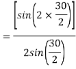
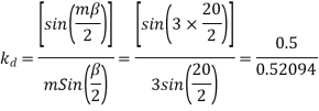
=0.9659
Since the flux is sinusoidally distributed

The generated voltage per phase is given by


Q20) A 3 phase, 50 hertz, 2 pole star connected turbo alternator has 54 slots with 4 conductors per slot the pitch of the coils is two slots less than the pole pitch. If the machine gives 3300V between lines on the open circuit with sinusoidal flux distribution, determine the useful flux per pole.
A20)


Coil pitch=25 slot angles


=0.95547
Total number of conductors per phase=

=72


Q21) A 4 pole, 3 phase, 50-hertz star connected alternator has 60 slots with two conductors per slot and having armature winding of two-layer type quasar short-pitched in such a way that if one coil sides lie in slot number one of the other lies in slot number 13. Determine the useful flux purple required to generate line voltage of 6000 volt.
A21)


Coil Span=12




Q22) A 3 phase 16 pole alternator has a star connected winding with 144 slots, and 10 conductors per slot. The flux per pole=0.03 Wb sinusoidally distributed, and speed is 375 rpm.
Find
1) Frequency
2) Phase voltage
3) Line voltage
A22)

Total conductors= 144×10=1440


For  as coil pitch is not mentioned take full pitched coil.
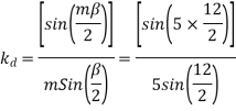
 =1
=1




For star connection,

Q23) A 3 phase 4 pole alternator has 60 slots, two conductors per slot. The pitch of the coils is 3 slots less than full pitch. Find 
A23)
Pole pitch=
Now 15 slots=180




Q24) Compare Salient pole and non-salient pole type synchronous machine?
A24)
Sr.No. | Salient pole type synchronous machine | Non-salient pole type synchronous machine |
1 | Diagram 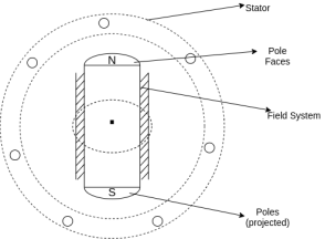
| Diagram 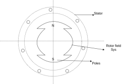 |
2 | Projected out poles | Merged in polls |
3 | Rotor surface is projected | Smooth rotor surface |
4 | The diameter of the machine is large | The small diameter of the machine |
5 | The axial length of the machine is small | The axial length of the machine is large |
6 | Speed is slow | Speed is high |
7 | Air gap is non uniform | Air gap is uniform |
8 | Damper bars/winding is used | Damper bar/winding not used |
9 | The air gap between stator and rotor is non-uniform | The air is uniform between stator and rotor |
10 | Centrifugal stress is more | Centrifugal stress is less |
11 | Aerodynamic resistance is more | Aerodynamic resistance is less |
Q25) Explain armature reaction and its effect under different load power factors.
A25)
Armature reaction
The effect of armature flux  on the flux produced by the field poles or the main flux
  is called armature reaction.
This effect is different for different nature of p.f. Of the load.
1) The effect may be cross magnetizing i.e.
2) It may be strong magnetizing or magnetizing i.e. is in the same direction as
  , So both are added, and the resultant field becomes stronger.
3) It may be demagnetizing i.e.  , and hence
  weakens.
Different nature of p.f.
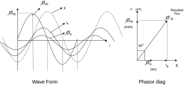
1) Unity PF
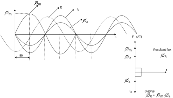
2) Zero PF lagging
3) Zero PF leading
Unity PF-: in this case  is in phase with E.
Phasors relations: -
1) E lag 
2)  in phase with E
3) Field ampere-turns i.e. F and 
4) Flux produced by  in phase with
  that is
The armature flux  crosses the main flux
  from the winding field, and vector diagram or Phasors.
Also, the armature flux crosses the resultant flux so for the unit PF the armature reaction is such that the main flux  is crossed or distorted. It is a cross magnetizing effect.
Zero lagging PF
It is seen that for lagging PF the armature flux is in direct opposition to flux  Hence it is demagnetizing, and resultant flux
Hence in the case of lagging PF, the effect of armature reaction is demagnetizing.
Q26) Explain armature reaction as per Blondel’s two-reaction theory for salient-pole machines.
A26)
Two reaction theory
Two reaction theory was proposed by, Andre Blondel. The theory proposes to resolve the given armature mmfs into two mutually perpendicular components, with one located along the axis of the rotor salient pole. It is known as the Direct axis component. The other component is located perpendicular to the axis of the rotor salient pole. It is known as the quadrature axis component. The d axis component of the armature MMF  is denoted by
  , and the q axis component by
  The component
  is either magnetizing or demagnetizing. The component
  results in a cross-magnetizing effect.
If  is the angle between the armature current
  , and the excitation voltage
  is the amplitude of the armature MMF, then

And 
Salient pole synchronous machine two reaction model
In the cylindrical rotor synchronous machine, the air gap is uniform. The protruding pole structure of the rotor of a salient pole machine makes the air gap highly non-uniform. Consider a two-pole rotor rotating in the anticlockwise direction within a two-pole stator.
The Axis along the axis of the rotor is called the d axis, and the axis perpendicular to the d axis is called the quadrature axis.
It is seen that the direct Axis flux path involves too small air gaps, and is the path of minimum reluctance. The path denoted by has too large air gaps, and is the path of maximum reluctance.
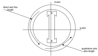
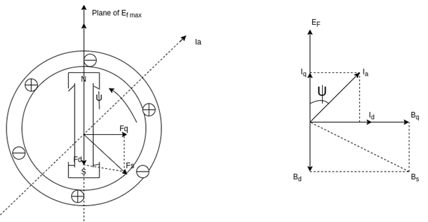
The rotor flux  is shown vertically upwards, this rotor flux induces a voltage
  in the stator.
If a lagging p.f. The load is connected to the synchronous generator, a stator current  will flow, and it lags behind the generated voltage
  by an angle
  .
.
The armature current produces stator mmf  which will lags behind
  by 90°. The stator MMF
  produces a magnetic field
  along its direction, and it can be resolved into two components the Direct axis component
  , and the quadrature axis component
Q27) A single 50 Hz synchronous generator on droop control was delivering 100 MW power to a system. Due to increase in load, generator power had to be increased by 10 MW, as a result of which, system frequency dropped to 49.75 Hz. Further increase in load in the system resulted in a frequency of 49.25 Hz. At this condition, the power in MW supplied by the generator is _______.
A27)
Given
f=50 Hz
Using f=-RP (i)
For 1st case:

P=+!0MW
f=
Using equation (i)
For 2nd case:


Using equation (i)

Dividing equation (iii) by equation (ii)
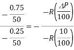


Q28) A cylindrical rotor synchronous generator has steady state synchronous reactance of 0.7 pu and sub transient reactance of 0.2 pu. It is operating at (1 + j0) pu terminal voltage with an internal emf of (1 + j0.7) pu. Following a three-phase solid short circuit fault at the terminal of the generator, the magnitude of the subtransient internal emf is ________ pu.
A28)


For a solid 3- fault,


Now subtransient internal emf


Q29) A cylindrical rotor synchronous generator with constant real power output and constant terminal voltage is supplying 100 A current to a 0.9 lagging power factor load. An ideal reactor is now connected in parallel with the load, as a result of which the total lagging reactive power requirement of the load is twice the previous value while the real power remains unchanged. The armature current is now_______ A.
A29)
Given I=100A
Cos =0.9

Real power =VI  constant
So

 [Terminal voltage remains constant]

 and
and


From equation (i)

Q30) Two parallel connected, three-phase, 50Hz, 11kV, star-connected synchronous machines A and B, are operating as synchronous condensers. They together supply 50 MVAR to a 11 kV grid. Current supplied by both the machines are equal. Synchronous reactance of machine A and machine B are and respectively. Assuming the magnetic circuit to be linear, the ratio of excitation current of machine A to that of machine B is ________.
A30)
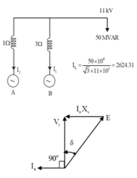

 current’s supplied both the machines are same

As the two motors, supplying reactive power only, the phasor diagram will be


Consider magnitudes 


Q31) A 3-phase, 2-pole, 50 Hz, synchronous generator has a rating of 250 MVA, 0.8 pf lagging. The kinetic energy of the machine at synchronous speed is 1000 MJ. The machine is running steadily at synchronous speed and delivering 60 MW power at a power angle of 10 electrical degrees. If the load is suddenly removed, assuming the acceleration is constant for 10 cycles, the value of the power angle after 5 cycles is ________ electrical degrees.
A31)


 cycles

New ratio δ = 10+2.7 = 
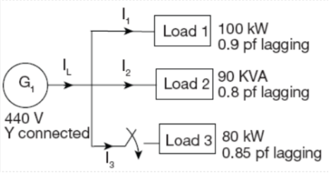
Q32) For the circuit given below, what real and reactive power are provided by the generator when the switch is closed?
A32)


Total real power =252 kW
Total reactive power =52.8 KVAr
Q33) A 25 kVA, 400 V, - Δ-connected, 3-phase, cylindrical rotor synchronous generator requires a field current of 5A to maintain the rated armature current under short-circuit condition. For the same field current, the open-circuit voltage is 360V. Neglecting the armature resistance and magnetic saturation, its voltage regulation (in % with respect to terminal voltage), when the generator delivers the rated load at 0.8 pf leading, at rated terminal voltage is _________.
A33)


Q34) A 30MVA, 3-phase, 50Hz 13.8kV, star-connected synchronous generator has positive, negative and zero sequence reactance, 15%, 15% and 5% respectively. A reactance (Xn ) is connected between the neutral of the generator and ground. A double line to ground fault takes place involving phases ‘b’ and ‘c’, with a fault impedance of j0.1 p.u. The value of Xn (in p.u) that will limit the positive sequence generator current to 4270 A is ________.
A34)


