Unit - 1
Data Communication Components
Q1) Differences b/w Simplex, Half-duplex and Full-duplex mode
A1)
Basis for comparison | Simplex mode | Half-duplex mode | Full-duplex mode |
Direction of communication | In simplex mode, the communication is unidirectional. | In half-duplex mode, the communication is bidirectional, but one at a time. | In full-duplex mode, the communication is bidirectional. |
Send/Receive | A device can only send the data but cannot receive it or it can only receive the data but cannot send it. | Both the devices can send and receive the data, but one at a time. | Both the devices can send and receive the data simultaneously. |
Performance | The performance of half-duplex mode is better than the simplex mode. | The performance of full-duplex mode is better than the half-duplex mode. | The Full-duplex mode has better performance among simplex and half-duplex mode as it doubles the utilization of the capacity of the communication channel. |
Example | Examples of Simplex mode are radio, keyboard, and monitor. | Example of half-duplex is Walkie-Talkies. | Example of the Full-duplex mode is a telephone network. |
Q2) Explain Bus topology in detail with advantages and disadvantages
A2) Bus Topology
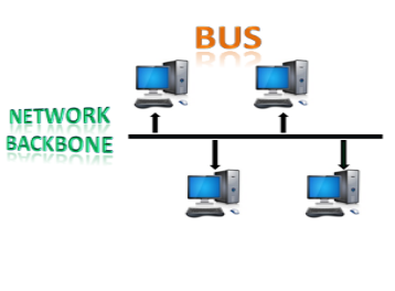
The bus topology is designed in such a way that all the stations are connected through a single cable known as a backbone cable.
Each node is either connected to the backbone cable by drop cable or directly connected to the backbone cable.
When a node wants to send a message over the network, it puts a message over the network. All the stations available in the network will receive the message whether it has been addressed or not.
The bus topology is mainly used in 802.3 (ethernet) and 802.4 standard networks.
The configuration of a bus topology is quite simpler as compared to other topologies.
The backbone cable is considered as a "single lane" through which the message is broadcast to all the stations.
The most common access method of the bus topologies is CSMA (Carrier Sense Multiple Access).
CSMA: It is a media access control used to control the data flow so that data integrity is maintained, i.e., the packets do not get lost. There are two alternative ways of handling the problems that occur when two nodes send the messages simultaneously.
CSMA CD: CSMA CD (Collision detection) is an access method used to detect the collision. Once the collision is detected, the sender will stop transmitting the data. Therefore, it works on "recovery after the collision".
CSMA CA: CSMA CA (Collision Avoidance) is an access method used to avoid the collision by checking whether the transmission media is busy or not. If busy, then the sender waits until the media becomes idle. This technique effectively reduces the possibility of the collision. It does not work on "recovery after the collision".
Advantages of Bus topology:
Low-cost cable: In bus topology, nodes are directly connected to the cable without passing through a hub. Therefore, the initial cost of installation is low.
Moderate data speeds: Coaxial or twisted pair cables are mainly used in bus-based networks that support upto 10 Mbps.
Familiar technology: Bus topology is a familiar technology as the installation and troubleshooting techniques are well known, and hardware components are easily available.
Limited failure: A failure in one node will not have any effect on other nodes.
Disadvantages of Bus topology:
Extensive cabling: A bus topology is quite simpler, but still it requires a lot of cabling.
Difficult troubleshooting: It requires specialized test equipment to determine the cable faults. If any fault occurs in the cable, then it would disrupt the communication for all the nodes.
Signal interference: If two nodes send the messages simultaneously, then the signals of both the nodes collide with each other.
Reconfiguration difficult: Adding new devices to the network would slow down the network.
Attenuation: Attenuation is a loss of signal leads to communication issues. Repeaters are used to regenerate the signal.
Q3) Explain Hybrid Topology write its advantages and disadvantages
A3) Hybrid Topology
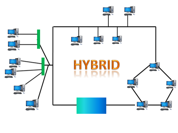
The combination of various different topologies is known as Hybrid topology.
A Hybrid topology is a connection between different links and nodes to transfer the data.
When two or more different topologies are combined together is termed as Hybrid topology and if similar topologies are connected with each other will not result in Hybrid topology. For example, if there exist a ring topology in one branch of ICICI bank and bus topology in another branch of ICICI bank, connecting these two topologies will result in Hybrid topology.
Advantages of Hybrid Topology
Reliable: If a fault occurs in any part of the network will not affect the functioning of the rest of the network.
Scalable: Size of the network can be easily expanded by adding new devices without affecting the functionality of the existing network.
Flexible: This topology is very flexible as it can be designed according to the requirements of the organization.
Effective: Hybrid topology is very effective as it can be designed in such a way that the strength of the network is maximized and weakness of the network is minimized.
Disadvantages of Hybrid topology
Complex design: The major drawback of the Hybrid topology is the design of the Hybrid network. It is very difficult to design the architecture of the Hybrid network.
Costly Hub: The Hubs used in the Hybrid topology are very expensive as these hubs are different from usual Hubs used in other topologies.
Costly infrastructure: The infrastructure cost is very high as a hybrid network requires a lot of cabling, network devices, etc.
Q4) What are the seven layers of OSI model?
A4) These are the seven layers of the OSI model −
Physical layer −It is the first layer that physically connects the two systems that need to communicate. It transmits data in bits and manages simplex or duplex transmission by modem. It also manages Network Interface Card’s hardware interface to the network, like cabling, cable terminators, topography, voltage levels, etc.
Data link layer − It is the firmware layer of Network Interface Card. It assembles datagrams into frames and adds start and stop flags to each frame. It also resolves problems caused by damaged, lost or duplicate frames.
Network layer − It is concerned with routing, switching and controlling flow of information between the workstations. It also breaks down transport layer datagrams into smaller datagrams.
Transport layer − Till the session layer, file is in its own form. Transport layer breaks it down into data frames, provides error checking at network segment level and prevents a fast host from overrunning a slower one. Transport layer isolates the upper layers from network hardware.
Session layer − This layer is responsible for establishing a session between two workstations that want to exchange data.
Presentation layer − This layer is concerned with correct representation of data, i.e. syntax and semantics of information. It controls file level security and is also responsible for converting data to network standards.
Application layer − It is the topmost layer of the network that is responsible for sending application requests by the user to the lower levels. Typical applications include file transfer, E-mail, remote logon, data entry, etc.
 |
It is not necessary for every network to have all the layers. For example, network layer is not there in broadcast networks.
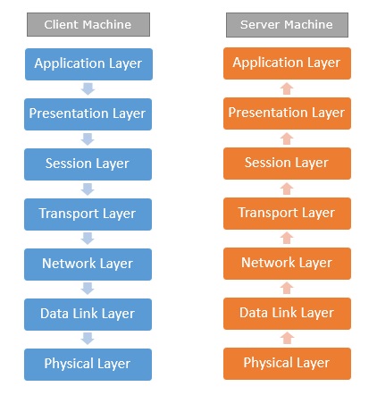
When a system wants to share data with another workstation or send a request over the network, it is received by the application layer. Data then proceeds to lower layers after processing till it reaches the physical layer.
At the physical layer, the data is actually transferred and received by the physical layer of the destination workstation. There, the data proceeds to upper layers after processing till it reaches application layer.
At the application layer, data or request is shared with the workstation. So each layer has opposite functions for source and destination workstations. For example, data link layer of the source workstation adds start and stop flags to the frames but the same layer of the destination workstation will remove the start and stop flags from the frames.
Q5) What is OSI Model and what are its characteristics?
A5) OSI stands for Open System Interconnection is a reference model that describes how information from a software application in one computer moves through a physical medium to the software application in another computer.
OSI consists of seven layers, and each layer performs a particular network function.
OSI model was developed by the International Organization for Standardization (ISO) in 1984, and it is now considered as an architectural model for the inter-computer communications.
OSI model divides the whole task into seven smaller and manageable tasks. Each layer is assigned a particular task.
Each layer is self-contained, so that task assigned to each layer can be performed independently.
Characteristics of OSI Model:
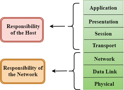 |
The OSI model is divided into two layers: upper layers and lower layers.
The upper layer of the OSI model mainly deals with the application related issues, and they are implemented only in the software. The application layer is closest to the end user. Both the end user and the application layer interact with the software applications. An upper layer refers to the layer just above another layer.
The lower layer of the OSI model deals with the data transport issues. The data link layer and the physical layer are implemented in hardware and software. The physical layer is the lowest layer of the OSI model and is closest to the physical medium. The physical layer is mainly responsible for placing the information on the physical medium.
Q6) What are the different functions of OSI layers explain each layer in detail?
A6) Functions of the OSI Layers
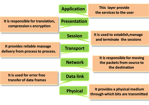
There are the seven OSI layers. Each layer has different functions. A list of seven layers is given below:
Physical Layer
Data-Link Layer
Network Layer
Transport Layer
Session Layer
Presentation Layer
Application Layer
 |
Physical layer
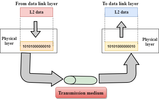 |
The main functionality of the physical layer is to transmit the individual bits from one node to another node.
It is the lowest layer of the OSI model.
It establishes, maintains and deactivates the physical connection.
It specifies the mechanical, electrical and procedural network interface specifications.
Functions of a Physical layer:
Line Configuration: It defines the way how two or more devices can be connected physically.
Data transmission: It defines the transmission mode whether it is simplex, half-duplex or full-duplex mode between the two devices on the network.
Topology: It defines the way how network devices are arranged.
Signals: It determines the type of the signal used for transmitting the information.
Data-Link Layer
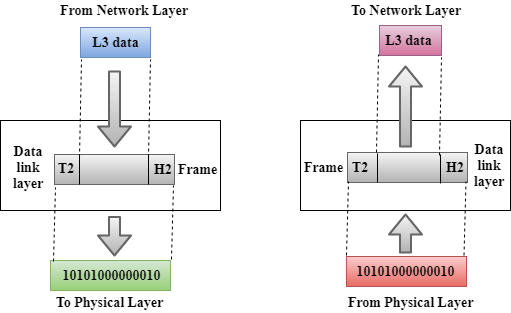 |
This layer is responsible for the error-free transfer of data frames.
It defines the format of the data on the network.
It provides a reliable and efficient communication between two or more devices.
It is mainly responsible for the unique identification of each device that resides on a local network.
It contains two sub-layers:
Logical Link Control Layer
It is responsible for transferring the packets to the Network layer of the receiver that is receiving.
It identifies the address of the network layer protocol from the header.
It also provides flow control.
Media Access Control Layer
A Media access control layer is a link between the Logical Link Control layer and the network's physical layer.
It is used for transferring the packets over the network.
Functions of the Data-link layer
Framing: The data link layer translates the physical's raw bit stream into packets known as Frames. The Data link layer adds the header and trailer to the frame. The header which is added to the frame contains the hardware destination and source address.
 |
Physical Addressing: The Data link layer adds a header to the frame that contains a destination address. The frame is transmitted to the destination address mentioned in the header.
Flow Control: Flow control is the main functionality of the Data-link layer. It is the technique through which the constant data rate is maintained on both the sides so that no data get corrupted. It ensures that the transmitting station such as a server with higher processing speed does not exceed the receiving station, with lower processing speed.
Error Control: Error control is achieved by adding a calculated value CRC (Cyclic Redundancy Check) that is placed to the Data link layer's trailer which is added to the message frame before it is sent to the physical layer. If any error seems to occurr, then the receiver sends the acknowledgment for the retransmission of the corrupted frames.
Access Control: When two or more devices are connected to the same communication channel, then the data link layer protocols are used to determine which device has control over the link at a given time.
Network Layer
 |
It is a layer 3 that manages device addressing, tracks the location of devices on the network.
It determines the best path to move data from source to the destination based on the network conditions, the priority of service, and other factors.
The Data link layer is responsible for routing and forwarding the packets.
Routers are the layer 3 devices, they are specified in this layer and used to provide the routing services within an internetwork.
The protocols used to route the network traffic are known as Network layer protocols. Examples of protocols are IP and Ipv6.
Functions of Network Layer:
Internetworking: An internetworking is the main responsibility of the network layer. It provides a logical connection between different devices.
Addressing: A Network layer adds the source and destination address to the header of the frame. Addressing is used to identify the device on the internet.
Routing: Routing is the major component of the network layer, and it determines the best optimal path out of the multiple paths from source to the destination.
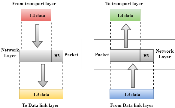
Packetizing: A Network Layer receives the packets from the upper layer and converts them into packets. This process is known as Packetizing. It is achieved by internet protocol (IP).
Transport Layer
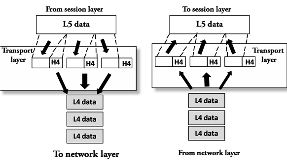 |
The Transport layer is a Layer 4 ensures that messages are transmitted in the order in which they are sent and there is no duplication of data.
The main responsibility of the transport layer is to transfer the data completely.
It receives the data from the upper layer and converts them into smaller units known as segments.
This layer can be termed as an end-to-end layer as it provides a point-to-point connection between source and destination to deliver the data reliably.
The two protocols used in this layer are:
Transmission Control Protocol
It is a standard protocol that allows the systems to communicate over the internet.
It establishes and maintains a connection between hosts.
When data is sent over the TCP connection, then the TCP protocol divides the data into smaller units known as segments. Each segment travels over the internet using multiple routes, and they arrive in different orders at the destination. The transmission control protocol reorders the packets in the correct order at the receiving end.
User Datagram Protocol
User Datagram Protocol is a transport layer protocol.
It is an unreliable transport protocol as in this case receiver does not send any acknowledgment when the packet is received, the sender does not wait for any acknowledgment. Therefore, this makes a protocol unreliable.
Functions of Transport Layer:
Service-point addressing: Computers run several programs simultaneously due to this reason, the transmission of data from source to the destination not only from one computer to another computer but also from one process to another process. The transport layer adds the header that contains the address known as a service-point address or port address. The responsibility of the network layer is to transmit the data from one computer to another computer and the responsibility of the transport layer is to transmit the message to the correct process.
Segmentation and reassembly: When the transport layer receives the message from the upper layer, it divides the message into multiple segments, and each segment is assigned with a sequence number that uniquely identifies each segment. When the message has arrived at the destination, then the transport layer reassembles the message based on their sequence numbers.
Connection control: Transport layer provides two services Connection-oriented service and connectionless service. A connectionless service treats each segment as an individual packet, and they all travel in different routes to reach the destination. A connection-oriented service makes a connection with the transport layer at the destination machine before delivering the packets. In connection-oriented service, all the packets travel in the single route.
Flow control: The transport layer also responsible for flow control but it is performed end-to-end rather than across a single link.
Error control: The transport layer is also responsible for Error control. Error control is performed end-to-end rather than across the single link. The sender transport layer ensures that message reach at the destination without any error.
Session Layer
 |
It is a layer 3 in the OSI model.
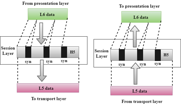
The Session layer is used to establish, maintain and synchronizes the interaction between communicating devices.
Functions of Session layer:
Dialog control: Session layer acts as a dialog controller that creates a dialog between two processes or we can say that it allows the communication between two processes which can be either half-duplex or full-duplex.
Synchronization: Session layer adds some checkpoints when transmitting the data in a sequence. If some error occurs in the middle of the transmission of data, then the transmission will take place again from the checkpoint. This process is known as Synchronization and recovery.
Presentation Layer
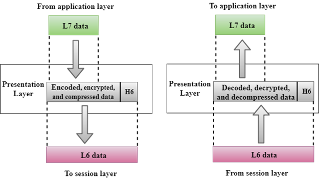 |
A Presentation layer is mainly concerned with the syntax and semantics of the information exchanged between the two systems.
It acts as a data translator for a network.
This layer is a part of the operating system that converts the data from one presentation format to another format.
The Presentation layer is also known as the syntax layer.
Functions of Presentation layer:
Translation: The processes in two systems exchange the information in the form of character strings, numbers and so on. Different computers use different encoding methods, the presentation layer handles the interoperability between the different encoding methods. It converts the data from sender-dependent format into a common format and changes the common format into receiver-dependent format at the receiving end.
Encryption: Encryption is needed to maintain privacy. Encryption is a process of converting the sender-transmitted information into another form and sends the resulting message over the network.
Compression: Data compression is a process of compressing the data, i.e., it reduces the number of bits to be transmitted. Data compression is very important in multimedia such as text, audio, video.
Application Layer
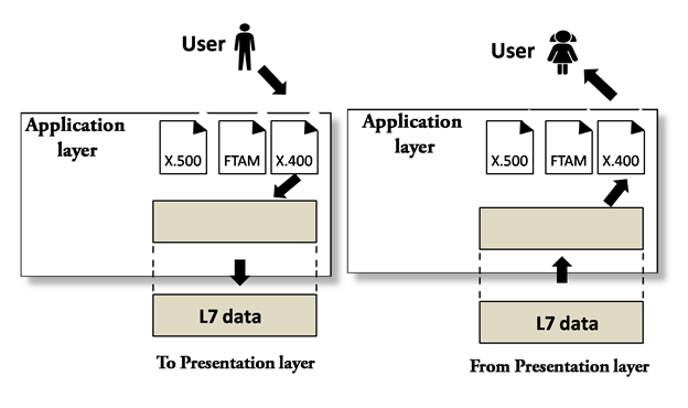 |
An application layer serves as a window for users and application processes to access network service.
It handles issues such as network transparency, resource allocation, etc.
An application layer is not an application, but it performs the application layer functions.
This layer provides the network services to the end-users.
Functions of Application layer:
File transfer, access, and management (FTAM): An application layer allows a user to access the files in a remote computer, to retrieve the files from a computer and to manage the files in a remote computer.
Mail services: An application layer provides the facility for email forwarding and storage.
Directory services: An application provides the distributed database sources and is used to provide that global information about various objects.
Q7) What is Transmission media?
A7) Transmission media is a communication channel that carries the information from the sender to the receiver. Data is transmitted through the electromagnetic signals.
The main functionality of the transmission media is to carry the information in the form of bits through LAN(Local Area Network).
It is a physical path between transmitter and receiver in data communication.
In a copper-based network, the bits in the form of electrical signals.
In a fibre based network, the bits in the form of light pulses.
In OSI(Open System Interconnection) phase, transmission media supports the Layer 1. Therefore, it is considered to be as a Layer 1 component.
The electrical signals can be sent through the copper wire, fibre optics, atmosphere, water, and vacuum.
The characteristics and quality of data transmission are determined by the characteristics of medium and signal.
Transmission media is of two types are wired media and wireless media. In wired media, medium characteristics are more important whereas, in wireless media, signal characteristics are more important.
Different transmission media have different properties such as bandwidth, delay, cost and ease of installation and maintenance.
The transmission media is available in the lowest layer of the OSI reference model, i.e., Physical layer.
Q8) What are some of the factors need to be considered for designing the transmission media?
A8) Some factors need to be considered for designing the transmission media:
Bandwidth: All the factors are remaining constant, the greater the bandwidth of a medium, the higher the data transmission rate of a signal.
Transmission impairment: When the received signal is not identical to the transmitted one due to the transmission impairment. The quality of the signals will get destroyed due to transmission impairment.
Interference: An interference is defined as the process of disrupting a signal when it travels over a communication medium on the addition of some unwanted signal.
Causes of Transmission Impairment:
 |
Attenuation: Attenuation means the loss of energy, i.e., the strength of the signal decreases with increasing the distance which causes the loss of energy.
Distortion: Distortion occurs when there is a change in the shape of the signal. This type of distortion is examined from different signals having different frequencies. Each frequency component has its own propagation speed, so they reach at a different time which leads to the delay distortion.
Noise: When data is travelled over a transmission medium, some unwanted signal is added to it which creates the noise.
Classification of Transmission Media:
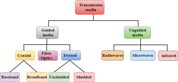 |
Guided Transmission Media
Unguided Transmission Media
Q9) What are the advantages and disadvantages of WLANs?
A9) Advantages of WLANs
Flexibility: Within radio coverage, nodes can communicate without further restriction. Radio waves can penetrate walls, senders and receivers can be placed anywhere (also non-visible, e.g., within devices, in walls etc.).
Planning: Only wireless ad-hoc networks allow for communication without previous planning, any wired network needs wiring plans.
Design: Wireless networks allow for the design of independent, small devices which can for example be put into a pocket. Cables not only restrict users but also designers of small notepads, PDAs, etc.
Robustness: Wireless networks can handle disasters, e.g., earthquakes, flood etc. whereas, networks requiring a wired infrastructure will usually break down completely in disasters.
Cost: The cost of installing and maintaining a wireless LAN is on average lower than the cost of installing and maintaining a traditional wired LAN, for two reasons. First, after providing wireless access to the wireless network via an access point for the first user, adding additional users to a network will not increase the cost. And second, wireless LAN eliminates the direct costs of cabling and the labor associated with installing and repairing it.
Ease of Use: Wireless LAN is easy to use and the users need very little new information to take advantage of WLANs.
Disadvantages of WLANs
Quality of Services: Quality of wireless LAN is typically lower than wired networks. The main reason for this is the lower bandwidth due to limitations is radio transmission, higher error rates due to interference and higher delay/delay variation due to extensive error correction and detection mechanisms.
Proprietary Solutions: Due to slow standardization procedures, many companies have come up with proprietary solutions offering standardization functionality plus many enhanced features. Most components today adhere to the basic standards IEEE 802.11a or 802.11b.
Restrictions: Several govt. And non-govt. Institutions world-wide regulate the operation and restrict frequencies to minimize interference.
Global operation: Wireless LAN products are sold in all countries so, national and international frequency regulations have to be considered.
Low Power: Devices communicating via a wireless LAN are typically power consuming, also wireless devices running on battery power. Whereas the LAN design should take this into account and implement special power saving modes and power management functions.
License free operation: LAN operators don't want to apply for a special license to be able to use the product. The equipment must operate in a license free band, such as the 2.4 GHz ISM band.
Robust transmission technology: If wireless LAN uses radio transmission, many other electrical devices can interfere with them (such as vacuum cleaner, train engines, hair dryers, etc.).Wireless LAN transceivers cannot be adjusted for perfect transmission is a standard office or production environment.
Q10) What is Virtual LAN and also write its features and types?
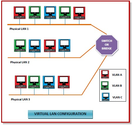
A10) Virtual Local Area Networks or Virtual LANs (VLANs) are a logical group of computers that appear to be on the same LAN irrespective of the configuration of the underlying physical network. Network administrators partition the networks to match the functional requirements of the VLANs so that each VLAN comprise of a subset of ports on a single or multiple switches or bridges. This allows computers and devices in a VLAN to communicate in the simulated environment as if it is a separate LAN.
 |
Features of VLANs
A VLAN forms sub-network grouping together devices on separate physical LANs.
VLAN's help the network manager to segment LANs logically into different broadcast domains.
VLANs function at layer 2, i.e. Data Link Layer of the OSI model.
There may be one or more network bridges or switches to form multiple, independent VLANs.
Using VLANs, network administrators can easily partition a single switched network into multiple networks depending upon the functional and security requirements of their systems.
VLANs eliminate the requirement to run new cables or reconfiguring physical connections in the present network infrastructure.
VLANs help large organizations to re-partition devices aiming improved traffic management.
VLANs also provide better security management allowing partitioning of devices according to their security criteria and also by ensuring a higher degree of control connected devices.
VLANs are more flexible than physical LANs since they are formed by logical connections. This aids is quicker and cheaper reconfiguration of devices when the logical partitioning needs to be changed.
Types of VLANs
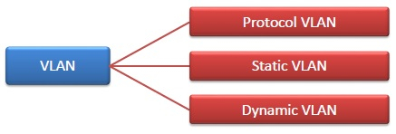 |
Protocol VLAN − Here, the traffic is handled based on the protocol used. A switch or bridge segregates, forwards or discards frames the come to it based upon the traffics protocol.
Port-based VLAN − This is also called static VLAN. Here, the network administrator assigns the ports on the switch / bridge to form a virtual network.
Dynamic VLAN − Here, the network administrator simply defines network membership according to device characteristics.