Unit - 3
Network Layer
Q1) What are Internetworking devices?
A1)
Internetworking is the technique of interconnecting myriad networks together, using connecting devices like routers and gateways. The different networks are owned by different entities that widely vary in terms of network technologies. These networks may be public, private, government, business or academic in nature, whose sizes may vary from small LANs to large WANs. The resulting network of networks is generally termed as internetwork or simply internet.
To enable efficient data communication among multiple networks, the connected networks decide upon a common protocol stack or communication methodology. The two architectural models that define the protocols used for communication are −
- Open System Interconnections model (OSI model)
- TCP/IP model or the Internet Protocol Suite.
Examples of internetworking
- The most widely used internetwork is the Internet (capitalization implies one specific internet), that uses the TCP/IP suite for interconnections. Its biggest service is the World Wide Web. The modern Internet in its present form came in the early 1990s. Since then it has been growing and is presently used by a few billion people all over the world.
- The predecessor of the Internet was ARPANET that was developed in the late 1960s and early 1970s. It was a packet switched network that developed protocols for internetworking.
Network Devices (Hub, Repeater, Bridge, Switch, Router, Gateways and Brouter)
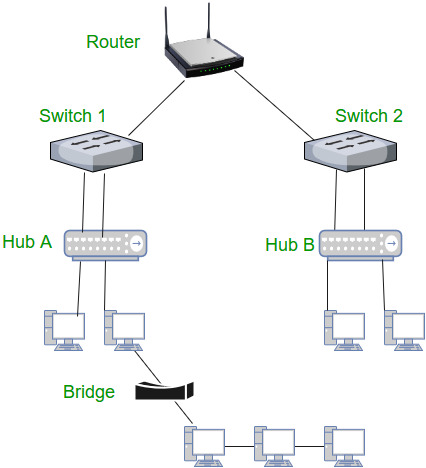
1. Repeater – A repeater operates at the physical layer. Its job is to regenerate the signal over the same network before the signal becomes too weak or corrupted so as to extend the length to which the signal can be transmitted over the same network. An important point to be noted about repeaters is that they do not amplify the signal. When the signal becomes weak, they copy the signal bit by bit and regenerate it at the original strength. It is a 2 port device.
2. Hub – A hub is basically a multiport repeater. A hub connects multiple wires coming from different branches, for example, the connector in star topology which connects different stations. Hubs cannot filter data, so data packets are sent to all connected devices. In other words, collision domain of all hosts connected through Hub remains one. Also, they do not have intelligence to find out best path for data packets which leads to inefficiencies and wastage.
Types of Hub
- Active Hub:- These are the hubs which have their own power supply and can clean, boost and relay the signal along with the network. It serves both as a repeater as well as wiring centre. These are used to extend the maximum distance between nodes.
- Passive Hub:- These are the hubs which collect wiring from nodes and power supply from active hub. These hubs relay signals onto the network without cleaning and boosting them and can’t be used to extend the distance between nodes.
3. Bridge – A bridge operates at data link layer. A bridge is a repeater, with add on the functionality of filtering content by reading the MAC addresses of source and destination. It is also used for interconnecting two LANs working on the same protocol. It has a single input and single output port, thus making it a 2 port device.
Types of Bridges
- Transparent Bridges: These are the bridge in which the stations are completely unaware of the bridge’s existence i.e. whether or not a bridge is added or deleted from the network, reconfiguration ofthe stations is unnecessary. These bridges make use of two processes i.e. bridge forwarding and bridge learning.
- Source Routing Bridges: In these bridges, routing operation is performed by source station and the frame specifies which route to follow. The hot can discover frame by sending a special frame called discovery frame, which spreads through the entire network using all possible paths to destination.
4. Switch – A switch is a multiport bridge with a buffer and a design that can boost its efficiency(a large number of ports imply less traffic) and performance. A switch is a data link layer device. The switch can perform error checking before forwarding data, that makes it very efficient as it does not forward packets that have errors and forward good packets selectively to correct port only. In other words, switch divides collision domain of hosts, but broadcast domain remains same.
5. Routers – A router is a device like a switch that routes data packets based on their IP addresses. Router is mainly a Network Layer device. Routers normally connect LANs and WANs together and have a dynamically updating routing table based on which they make decisions on routing the data packets. Router divide broadcast domains of hosts connected through it.
6. Gateway – A gateway, as the name suggests, is a passage to connect two networks together that may work upon different networking models. They basically work as the messenger agents that take data from one system, interpret it, and transfer it to another system. Gateways are also called protocol converters and can operate at any network layer. Gateways are generally more complex than switch or router.
7. Brouter – It is also known as bridging router is a device which combines features of both bridge and router. It can work either at data link layer or at network layer. Working as router, it is capable of routing packets across networks and working as bridge, it is capable of filtering local area network traffic.
Q2) Explain IP Addressing.
A2)
- Network Addressing is one of the major responsibilities of the network layer.
- Network addresses are always logical, i.e., software-based addresses.
- A host is also known as end system that has one link to the network. The boundary between the host and link is known as an interface. Therefore, the host can have only one interface.
- A router is different from the host in that it has two or more links that connect to it. When a router forwards the datagram, then it forwards the packet to one of the links. The boundary between the router and link is known as an interface, and the router can have multiple interfaces, one for each of its links. Each interface is capable of sending and receiving the IP packets, so IP requires each interface to have an address.
- Each IP address is 32 bits long, and they are represented in the form of "dot-decimal notation" where each byte is written in the decimal form, and they are separated by the period. An IP address would look like 193.32.216.9 where 193 represents the decimal notation of first 8 bits of an address, 32 represents the decimal notation of second 8 bits of an address.
Let’s understand through a simple example
.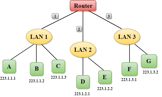
- In the above figure, a router has three interfaces labeled as 1, 2 & 3 and each router interface contains its own IP address.
- Each host contains its own interface and IP address.
- All the interfaces attached to the LAN 1 is having an IP address in the form of 223.1.1.xxx, and the interfaces attached to the LAN 2 and LAN 3 have an IP address in the form of 223.1.2.xxx and 223.1.3.xxx respectively.
- Each IP address consists of two parts. The first part (first three bytes in IP address) specifies the network and second part (last byte of an IP address) specifies the host in the network.
Classful Addressing
An IP address is 32-bit long. An IP address is divided into sub-classes:
- Class A
- Class B
- Class C
- Class D
- Class E
An ip address is divided into two parts:
- Network ID: It represents the number of networks.
- Host ID: It represents the number of hosts.
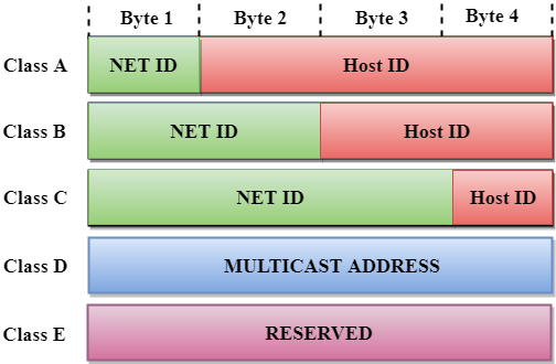
In the above diagram, we observe that each class have a specific range of IP addresses. The class of IP address is used to determine the number of bits used in a class and number of networks and hosts available in the class.
Class A
In Class A, an IP address is assigned to those networks that contain a large number of hosts.
- The network ID is 8 bits long.
- The host ID is 24 bits long.
In Class A, the first bit in higher order bits of the first octet is always set to 0 and the remaining 7 bits determine the network ID. The 24 bits determine the host ID in any network.
The total number of networks in Class A = 27 = 128 network address
The total number of hosts in Class A = 224 - 2 = 16,777,214 host address

Class B
In Class B, an IP address is assigned to those networks that range from small-sized to large-sized networks.
- The Network ID is 16 bits long.
- The Host ID is 16 bits long.
In Class B, the higher order bits of the first octet is always set to 10, and the remaining14 bits determine the network ID. The other 16 bits determine the Host ID.
The total number of networks in Class B = 214 = 16384 network address
The total number of hosts in Class B = 216 - 2 = 65534 host address

Class C
In Class C, an IP address is assigned to only small-sized networks.
- The Network ID is 24 bits long.
- The host ID is 8 bits long.
In Class C, the higher order bits of the first octet is always set to 110, and the remaining 21 bits determine the network ID. The 8 bits of the host ID determine the host in a network.
The total number of networks = 221 = 2097152 network address
The total number of hosts = 28 - 2 = 254 host address

Class D
In Class D, an IP address is reserved for multicast addresses. It does not possess subnetting. The higher order bits of the first octet is always set to 1110, and the remaining bits determines the host ID in any network.

Class E
In Class E, an IP address is used for the future use or for the research and development purposes. It does not possess any subnetting. The higher order bits of the first octet is always set to 1111, and the remaining bits determines the host ID in any network.

Rules for assigning Host ID:
The Host ID is used to determine the host within any network. The Host ID is assigned based on the following rules:
- The Host ID must be unique within any network.
- The Host ID in which all the bits are set to 0 cannot be assigned as it is used to represent the network ID of the IP address.
- The Host ID in which all the bits are set to 1 cannot be assigned as it is reserved for the multicast address.
Rules for assigning Network ID:
If the hosts are located within the same local network, then they are assigned with the same network ID. The following are the rules for assigning Network ID:
- The network ID cannot start with 127 as 127 is used by Class A.
- The Network ID in which all the bits are set to 0 cannot be assigned as it is used to specify a particular host on the local network.
- The Network ID in which all the bits are set to 1 cannot be assigned as it is reserved for the multicast address.
Classful Network Architecture
Class | Higher bits | NET ID bits | HOST ID bits | No. Of networks | No. Of hosts per network | Range |
A | 0 | 8 | 24 | 27 | 224 | 0.0.0.0 to 127.255.255.255 |
B | 10 | 16 | 16 | 214 | 216 | 128.0.0.0 to 191.255.255.255 |
C | 110 | 24 | 8 | 221 | 28 | 192.0.0.0 to 223.255.255.255 |
D | 1110 | Not Defined | Not Defined | Not Defined | Not Defined | 224.0.0.0 to 239.255.255.255 |
E | 1111 | Not Defined | Not Defined | Not Defined | Not Defined | 240.0.0.0 to 255.255.255.255 |
Q3) What is subnetting? Write its advantages and disadvantages.
A3)
Subnetting
- Subnetting is the act of dividing a network into subnetworks, and supernetting is the process of joining small networks into a large network. Subnetting increases the number of bits in network addresses, while supernetting increases the number of bits in host addresses. Supernetting is a technique for making the routing process easier. It decreases the size of routing table data, which means it takes up less memory in the router. For subnetting, FLSM and VLSM are utilized, while CIDR is used for supernetting.
- Subnetting is a technique for dividing a single physical network into smaller sub-networks. A subnet is a collection of subnetworks. The small networks section and the host segment combine to form an internal address. A subnetwork is created by accepting the bits from the IP address host component and using them to create a number of mini subnetworks within the original network.
- Network bits are turned into host bits during the subnetting process. The process of subnetting is used to slow down the depletion of IP addresses. It enables the administrator to divide a single class A, B, or C into smaller portions. VLSM (Variable Length Subnet Mask) and FLSM (Fixed Length Subnet Mask) are used in subnetting (Fixed Length Subnet Mask). A Variable Length Subnet Mask is a method of dividing the IP address space into subnets of varying sizes. Memory waste is reduced with VLSM. A Fixed Length Subnet Mask is a method of dividing the IP address space into subnets of the same size.
Advantages
- The number of authorized hosts in a local area network can be increased via subnetting.
- Subnetting reduces the amount of broadcast traffic and thus the amount of network traffic.
- Subnetworks are simple to set up and manage.
- Subnetting increases the address's versatility.
- Rather than using network security across the entire network, subnetwork security can be easily implemented.
Disadvantages:
- Subnetting is a time-consuming and costly operation.
- A trained administrator is required to carry out the subnetting operation.
Q4) Explain Routing algorithms.
A4)
Routing algorithm
- In order to transfer the packets from source to the destination, the network layer must determine the best route through which packets can be transmitted.
- Whether the network layer provides datagram service or virtual circuit service, the main job of the network layer is to provide the best route. The routing protocol provides this job.
- The routing protocol is a routing algorithm that provides the best path from the source to the destination. The best path is the path that has the "least-cost path" from source to the destination.
- Routing is the process of forwarding the packets from source to the destination but the best route to send the packets is determined by the routing algorithm.
Classification of a Routing algorithm
The Routing algorithm is divided into two categories:
- Adaptive Routing algorithm
- Non-adaptive Routing algorithm
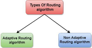
Fig – Types of routing algorithm
Adaptive Routing algorithm
- An adaptive routing algorithm is also known as dynamic routing algorithm.
- This algorithm makes the routing decisions based on the topology and network traffic.
- The main parameters related to this algorithm are hop count, distance and estimated transit time.
An adaptive routing algorithm can be classified into three parts:
- Centralized algorithm: It is also known as global routing algorithm as it computes the least-cost path between source and destination by using complete and global knowledge about the network. This algorithm takes the connectivity between the nodes and link cost as input, and this information is obtained before actually performing any calculation. Link state algorithm is referred to as a centralized algorithm since it is aware of the cost of each link in the network.
- Isolation algorithm: It is an algorithm that obtains the routing information by using local information rather than gathering information from other nodes.
- Distributed algorithm: It is also known as decentralized algorithm as it computes the least-cost path between source and destination in an iterative and distributed manner. In the decentralized algorithm, no node has the knowledge about the cost of all the network links. In the beginning, a node contains the information only about its own directly attached links and through an iterative process of calculation computes the least-cost path to the destination. A Distance vector algorithm is a decentralized algorithm as it never knows the complete path from source to the destination, instead it knows the direction through which the packet is to be forwarded along with the least cost path.
Non-Adaptive Routing algorithm
- Non Adaptive routing algorithm is also known as a static routing algorithm.
- When booting up the network, the routing information stores to the routers.
- Non Adaptive routing algorithms do not take the routing decision based on the network topology or network traffic.
The Non-Adaptive Routing algorithm is of two types:
Flooding: In case of flooding, every incoming packet is sent to all the outgoing links except the one from it has been reached. The disadvantage of flooding is that node may contain several copies of a particular packet.
Random walks: In case of random walks, a packet sent by the node to one of its neighbors randomly. An advantage of using random walks is that it uses the alternative routes very efficiently.
Q5) What is ICMP?
A5)
The ICMP stands for Internet Control Message Protocol. The ICMP protocol is a network layer protocol that hosts and routers use to notify the sender of IP datagram problems. The echo test/reply method is used by ICMP to determine if the destination is reachable and responding.
ICMP can handle both control and error messages, but its primary purpose is to record errors rather than to fix them. An IP datagram includes the source and destination addresses, but it does not know the address of the previous router it passed through.
As a result, ICMP can only send messages to the source, not to the routers in the immediate vicinity. The sender receives error messages via the ICMP protocol. The errors are returned to the user processes via ICMP messages.
ICMP messages are sent as part of an IP datagram.
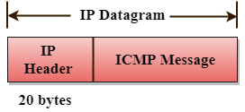
Fig: ICMP
Format of ICMP

Fig: ICMP format
- The message's form is defined in the first sector.
- The reason for a particular message form is specified in the second sector.
- The checksum field is used to verify the integrity of the entire ICMP message.
Key takeaway
The ICMP stands for Internet Control Message Protocol. The ICMP protocol is a network layer protocol that hosts and routers use to notify the sender of IP datagram problems. The echo test/reply method is used by ICMP to determine if the destination is reachable and responding.
Q6) What is IP address and explain IPv4 in detail and its drawbacks?
A6) An IP stands for internet protocol. An IP address is assigned to each device connected to a network. Each device uses an IP address for communication. It also behaves as an identifier as this address is used to identify the device on a network. It defines the technical format of the packets. Mainly, both the networks, i.e., IP and TCP, are combined together, so together, they are referred to as a TCP/IP. It creates a virtual connection between the source and the destination.
We can also define an IP address as a numeric address assigned to each device on a network. An IP address is assigned to each device so that the device on a network can be identified uniquely. To facilitate the routing of packets, TCP/IP protocol uses a 32-bit logical address known as IPv4(Internet Protocol version 4).
An IP address consists of two parts, i.e., the first one is a network address, and the other one is a host address.
There are two types of IP addresses:
IPv4
IPv6
What is IPv4?
IPv4 is a version 4 of IP. It is a current version and the most commonly used IP address. It is a 32-bit address written in four numbers separated by 'dot', i.e., periods. This address is unique for each device.
For example, 66.94.29.13
The above example represents the IP address in which each group of numbers separated by periods is called an Octet. Each number in an octet is in the range from 0-255. This address can produce 4,294,967,296 possible unique addresses.
In today's computer network world, computers do not understand the IP addresses in the standard numeric format as the computers understand the numbers in binary form only. The binary number can be either 1 or 0. The IPv4 consists of four sets, and these sets represent the octet. The bits in each octet represent a number.
Each bit in an octet can be either 1 or 0. If the bit the 1, then the number it represents will count, and if the bit is 0, then the number it represents does not count.
Representation of 8 Bit Octet

The above representation shows the structure of 8- bit octet.
Now, we will see how to obtain the binary representation of the above IP address, i.e., 66.94.29.13
Step 1: First, we find the binary number of 66.

To obtain 66, we put 1 under 64 and 2 as the sum of 64 and 2 is equal to 66 (64+2=66), and the remaining bits will be zero, as shown above. Therefore, the binary bit version of 66 is 01000010.
Step 2: Now, we calculate the binary number of 94.

To obtain 94, we put 1 under 64, 16, 8, 4, and 2 as the sum of these numbers is equal to 94, and the remaining bits will be zero. Therefore, the binary bit version of 94 is 01011110.
Step 3: The next number is 29.

To obtain 29, we put 1 under 16, 8, 4, and 1 as the sum of these numbers is equal to 29, and the remaining bits will be zero. Therefore, the binary bit version of 29 is 00011101.
Step 4: The last number is 13.

To obtain 13, we put 1 under 8, 4, and 1 as the sum of these numbers is equal to 13, and the remaining bits will be zero. Therefore, the binary bit version of 13 is 00001101.
Drawback of IPv4
Currently, the population of the world is 7.6 billion. Every user is having more than one device connected with the internet, and private companies also rely on the internet. As we know that IPv4 produces 4 billion addresses, which are not enough for each device connected to the internet on a planet. Although the various techniques were invented, such as variable- length mask, network address translation, port address translation, classes, inter-domain translation, to conserve the bandwidth of IP address and slow down the depletion of an IP address. In these techniques, public IP is converted into a private IP due to which the user having public IP can also use the internet. But still, this was not so efficient, so it gave rise to the development of the next generation of IP addresses, i.e., IPv6.
Q7) What is IPv6?
A7) IPv4 produces 4 billion addresses, and the developers think that these addresses are enough, but they were wrong. IPv6 is the next generation of IP addresses. The main difference between IPv4 and IPv6 is the address size of IP addresses. The IPv4 is a 32-bit address, whereas IPv6 is a 128-bit hexadecimal address. IPv6 provides a large address space, and it contains a simple header as compared to IPv4.
It provides transition strategies that convert IPv4 into IPv6, and these strategies are as follows:
Dual stacking: It allows us to have both the versions, i.e., IPv4 and IPv6, on the same device.
Tunneling: In this approach, all the users have IPv6 communicates with an IPv4 network to reach IPv6.
Network Address Translation: The translation allows the communication between the hosts having a different version of IP.
This hexadecimal address contains both numbers and alphabets. Due to the usage of both the numbers and alphabets, IPv6 is capable of producing over 340 undecillion (3.4*1038) addresses.
IPv6 is a 128-bit hexadecimal address made up of 8 sets of 16 bits each, and these 8 sets are separated by a colon. In IPv6, each hexadecimal character represents 4 bits. So, we need to convert 4 bits to a hexadecimal number at a time
Address format
The address format of IPv4:

The address format of IPv6:

The above diagram shows the address format of IPv4 and IPv6. An IPv4 is a 32-bit decimal address. It contains 4 octets or fields separated by 'dot', and each field is 8-bit in size. The number that each field contains should be in the range of 0-255. Whereas an IPv6 is a 128-bit hexadecimal address. It contains 8 fields separated by a colon, and each field is 16-bit in size.
Q8) Differences between IPv4 and IPv6
A8)
| Ipv4 | Ipv6 |
Address length | IPv4 is a 32-bit address. | IPv6 is a 128-bit address. |
Fields | IPv4 is a numeric address that consists of 4 fields which are separated by dot (.). | IPv6 is an alphanumeric address that consists of 8 fields, which are separated by colon. |
Classes | IPv4 has 5 different classes of IP address that includes Class A, Class B, Class C, Class D, and Class E. | IPv6 does not contain classes of IP addresses. |
Number of IP address | IPv4 has a limited number of IP addresses. | IPv6 has a large number of IP addresses. |
VLSM | It supports VLSM (Virtual Length Subnet Mask). Here, VLSM means that Ipv4 converts IP addresses into a subnet of different sizes. | It does not support VLSM. |
Address configuration | It supports manual and DHCP configuration. | It supports manual, DHCP, auto-configuration, and renumbering. |
Address space | It generates 4 billion unique addresses | It generates 340 undecillion unique addresses. |
End-to-end connection integrity | In IPv4, end-to-end connection integrity is unachievable. | In the case of IPv6, end-to-end connection integrity is achievable. |
Security features | In IPv4, security depends on the application. This IP address is not developed in keeping the security feature in mind. | In IPv6, IPSEC is developed for security purposes. |
Address representation | In IPv4, the IP address is represented in decimal. | In IPv6, the representation of the IP address in hexadecimal. |
Fragmentation | Fragmentation is done by the senders and the forwarding routers. | Fragmentation is done by the senders only. |
Packet flow identification | It does not provide any mechanism for packet flow identification. | It uses flow label field in the header for the packet flow identification. |
Checksum field | The checksum field is available in IPv4. | The checksum field is not available in IPv6. |
Transmission scheme | IPv4 is broadcasting. | On the other hand, IPv6 is multicasting, which provides efficient network operations. |
Encryption and Authentication | It does not provide encryption and authentication. | It provides encryption and authentication. |
Number of octets | It consists of 4 octets. | It consists of 8 fields, and each field contains 2 octets. Therefore, the total number of octets in IPv6 is 16. |
Q9) What is Address Resolution Protocol (ARP) and what are its types?
A9) Address Resolution Protocol (ARP) is a communication protocol used to find the MAC (Media Access Control) address of a device from its IP address. This protocol is used when a device wants to communicate with another device on a Local Area Network or Ethernet.
Types of ARP
There are four types of Address Resolution Protocol, which is given below:
Proxy ARP
Gratuitous ARP
Reverse ARP (RARP)
Inverse ARP
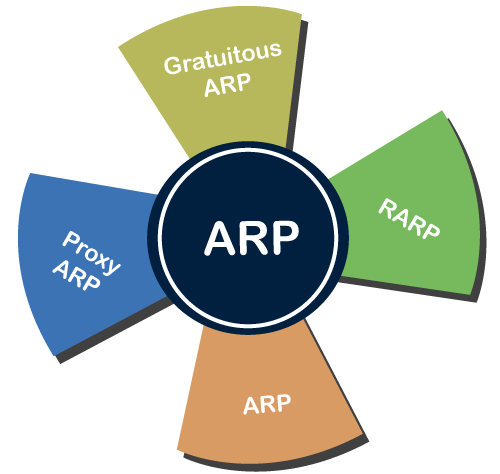
Proxy ARP - Proxy ARP is a method through which a Layer 3 devices may respond to ARP requests for a target that is in a different network from the sender. The Proxy ARP configured router responds to the ARP and map the MAC address of the router with the target IP address and fool the sender that it is reached at its destination.
At the backend, the proxy router sends its packets to the appropriate destination because the packets contain the necessary information.
Example - If Host A wants to transmit data to Host B, which is on the different network, then Host A sends an ARP request message to receive a MAC address for Host B. The router responds to Host A with its own MAC address pretend itself as a destination. When the data is transmitted to the destination by Host A, it will send to the gateway so that it sends to Host B. This is known as proxy ARP.
Gratuitous ARP - Gratuitous ARP is an ARP request of the host that helps to identify the duplicate IP address. It is a broadcast request for the IP address of the router. If an ARP request is sent by a switch or router to get its IP address and no ARP responses are received, so all other nodes cannot use the IP address allocated to that switch or router. Yet if a router or switch sends an ARP request for its IP address and receives an ARP response, another node uses the IP address allocated to the switch or router.
There are some primary use cases of gratuitous ARP that are given below:
The gratuitous ARP is used to update the ARP table of other devices.
It also checks whether the host is using the original IP address or a duplicate one.
Reverse ARP (RARP) - It is a networking protocol used by the client system in a local area network (LAN) to request its IPv4 address from the ARP gateway router table. A table is created by the network administrator in the gateway-router that is used to find out the MAC address to the corresponding IP address.
When a new system is set up or any machine that has no memory to store the IP address, then the user has to find the IP address of the device. The device sends a RARP broadcast packet, including its own MAC address in the address field of both the sender and the receiver hardware. A host installed inside of the local network called the RARP-server is prepared to respond to such type of broadcast packet. The RARP server is then trying to locate a mapping table entry in the IP to MAC address. If any entry matches the item in the table, then the RARP server sends the response packet along with the IP address to the requesting computer.
Inverse ARP (InARP) - Inverse ARP is inverse of the ARP, and it is used to find the IP addresses of the nodes from the data link layer addresses. These are mainly used for the frame relays, and ATM networks, where Layer 2 virtual circuit addressing are often acquired from Layer 2 signaling. When using these virtual circuits, the relevant Layer 3 addresses are available.
ARP conversions Layer 3 addresses to Layer 2 addresses. However, its opposite address can be defined by InARP. The InARP has a similar packet format as ARP, but operational codes are different.
Q10) Explain Dynamic Host Configuration Protocol its components and benefits
A10) Dynamic Host Configuration Protocol (DHCP) is a network management protocol used to dynamically assign an IP address to nay device, or node, on a network so they can communicate using IP (Internet Protocol). DHCP automates and centrally manages these configurations. There is no need to manually assign IP addresses to new devices. Therefore, there is no requirement for any user configuration to connect to a DHCP based network.
DHCP can be implemented on local networks as well as large enterprise networks. DHCP is the default protocol used by the most routers and networking equipment. DHCP is also called RFC (Request for comments) 2131.
DHCP does the following:
DHCP manages the provision of all the nodes or devices added or dropped from the network.
DHCP maintains the unique IP address of the host using a DHCP server.
It sends a request to the DHCP server whenever a client/node/device, which is configured to work with DHCP, connects to a network. The server acknowledges by providing an IP address to the client/node/device.
DHCP is also used to configure the proper subnet mask, default gateway and DNS server information on the node or device.
There are many versions of DCHP are available for use in IPV4 (Internet Protocol Version 4) and IPV6 (Internet Protocol Version 6).
How DHCP works
DHCP runs at the application layer of the TCP/IP protocol stack to dynamically assign IP addresses to DHCP clients/nodes and to allocate TCP/IP configuration information to the DHCP clients. Information includes subnet mask information, default gateway, IP addresses and domain name system addresses.
DHCP is based on client-server protocol in which servers manage a pool of unique IP addresses, as well as information about client configuration parameters, and assign addresses out of those address pools.
The DHCP lease process works as follows:
First of all, a client (network device) must be connected to the internet.
DHCP clients request an IP address. Typically, client broadcasts a query for this information.
DHCP server responds to the client request by providing IP server address and other configuration information. This configuration information also includes time period, called a lease, for which the allocation is valid.
When refreshing an assignment, a DHCP clients request the same parameters, but the DHCP server may assign a new IP address. This is based on the policies set by the administrator.
Components of DHCP
When working with DHCP, it is important to understand all of the components. Following are the list of components:
DHCP Server: DHCP server is a networked device running the DCHP service that holds IP addresses and related configuration information. This is typically a server or a router but could be anything that acts as a host, such as an SD-WAN appliance.
DHCP client: DHCP client is the endpoint that receives configuration information from a DHCP server. This can be any device like computer, laptop, IoT endpoint or anything else that requires connectivity to the network. Most of the devices are configured to receive DHCP information by default.
IP address pool: IP address pool is the range of addresses that are available to DHCP clients. IP addresses are typically handed out sequentially from lowest to the highest.
Subnet: Subnet is the partitioned segments of the IP networks. Subnet is used to keep networks manageable.
Lease: Lease is the length of time for which a DHCP client holds the IP address information. When a lease expires, the client has to renew it.
DHCP relay: A host or router that listens for client messages being broadcast on that network and then forwards them to a configured server. The server then sends responses back to the relay agent that passes them along to the client. DHCP relay can be used to centralize DHCP servers instead of having a server on each subnet.
Benefits of DHCP
There are following benefits of DHCP:
Centralized administration of IP configuration: DHCP IP configuration information can be stored in a single location and enables that administrator to centrally manage all IP address configuration information.
Dynamic host configuration: DHCP automates the host configuration process and eliminates the need to manually configure individual host. When TCP/IP (Transmission control protocol/Internet protocol) is first deployed or when IP infrastructure changes are required.
Seamless IP host configuration: The use of DHCP ensures that DHCP clients get accurate and timely IP configuration IP configuration parameter such as IP address, subnet mask, default gateway, IP address of DND server and so on without user intervention.
Flexibility and scalability: Using DHCP gives the administrator increased flexibility, allowing the administrator to move easily change IP configuration when the infrastructure changes.
Q11) Write differences b/w Adaptive and Non-Adaptive Routing Algorithm
A11)
Basis Of Comparison | Adaptive Routing algorithm | Non-Adaptive Routing algorithm |
Define | Adaptive Routing algorithm is an algorithm that constructs the routing table based on the network conditions. | The Non-Adaptive Routing algorithm is an algorithm that constructs the static table to determine which node to send the packet. |
Usage | Adaptive routing algorithm is used by dynamic routing. | The Non-Adaptive Routing algorithm is used by static routing. |
Routing decision | Routing decisions are made based on topology and network traffic. | Routing decisions are the static tables. |
Categorization | The types of adaptive routing algorithm, are Centralized, isolation and distributed algorithm. | The types of Non Adaptive routing algorithm are flooding and random walks. |
Complexity | Adaptive Routing algorithms are more complex. | Non-Adaptive Routing algorithms are simple. |
Q12) Explain distance vector routing protocol with example.
A12)
A distance-vector routing (DVR) protocol is that it requires that a router should inform its neighbors of topology changes takes place periodically. Historically it is known as the old ARPANET routing algorithm (or it is also known as Bellman-Ford algorithm).
Bellman Ford Basics – Each router maintains its Distance Vector table which contains the distance between itself and all possible destination nodes. Distances is based on a chosen metric and are computed using information from the neighbors’ distance vectors.
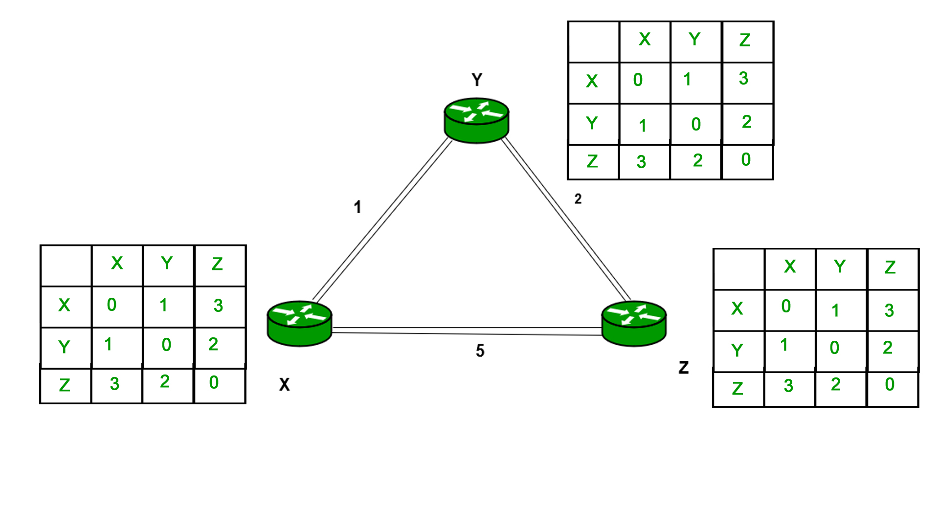
Example - Consider 3-routers X5 Y and Z as shown in figure. Each router have their routing table. Every routing table will contain distance to the destination nodes.
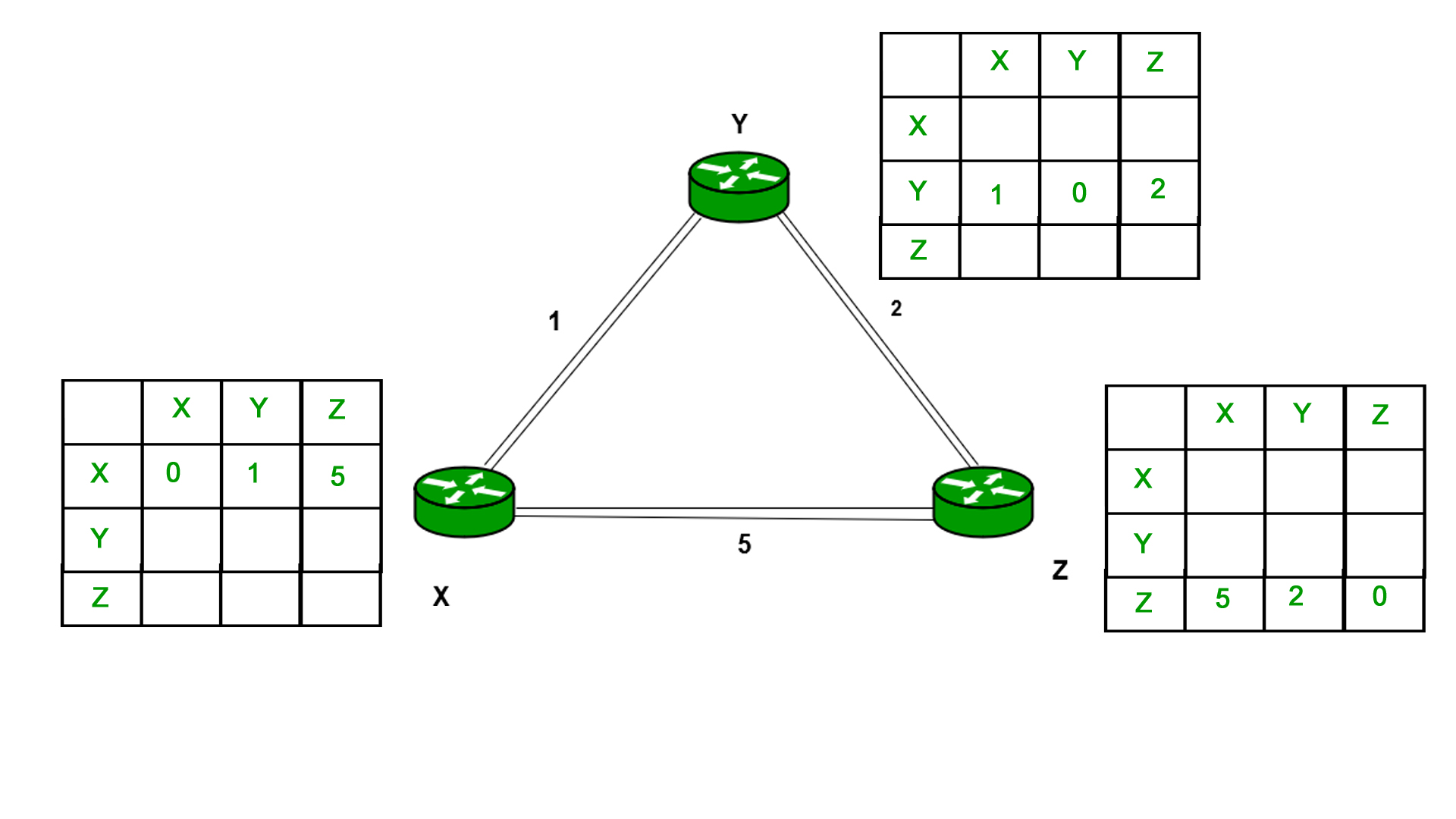
Consider router X 5 X will share it routing table to neighbors and neighbors will share it routing table to it to X and distance from node X to destination will be calculated using bellmen- ford equation.
Dx(y) = min { C(x5v) + Dv(y)} for each node y ∈ N
As we can see that distance will be less going from X to Z when Y is intermediate node (hop) so it will be update in routing table X.
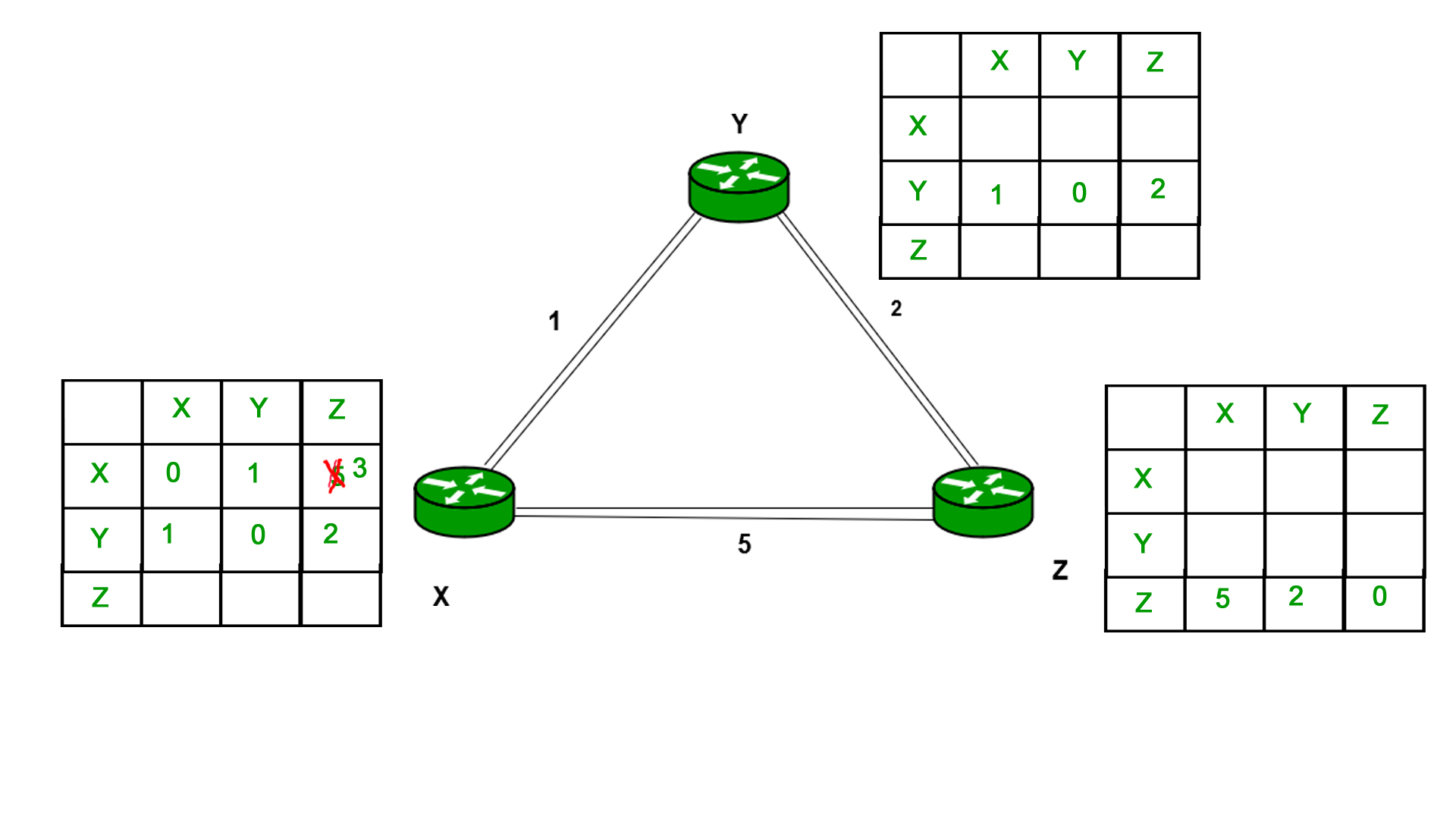
Similarly for Z also –
Finally, the routing table for all is shown above image.
Information which are kept by DV router -
● Each router has its own ID
● IT is associated with each link that are connected to a router,
● There is a cost of the link (static or dynamic).
● Intermediate hops
Distance Vector Table Initialization -
● Distance to itself = 0
● Distance to all other routers = infinity number.
Distance Vector Algorithm –
1. A router transmits its distance vector to that of each of its neighbors in that of a routing packet.
2. Each router receives and then saves the most recently received distance vector from each of its neighbors.
3. A router recalculates its distance vector when the following happens:
○ It receives a distance vector from that of its neighbor containing different information than before.
○ It discovers that a link to a neighbor has slow down.
The DV calculation is based on minimizing the cost to each destination
Dx(y) = Estimate of least cost from x to y
C(x,v) = Node x knows cost to each neighbor v
Dx = [Dx(y): y ∈ N] = Node x maintains distance vector
Node x also maintains its neighbors’ distance vectors
– For each neighbor v, x maintains Dv = [Dv(y): y ∈N ]
Note –
● From time-to-time, each of the node sends its own distance vector which is estimate to its neighbors.
● When a node x receives new DV estimate from any neighbor v, it saves v’s distance vector and it updates its own DV using B-F equation:
● Dx(y) = min { C(x,v) + Dv(y)} for each node y ∈ N
Advantages of Distance Vector routing are as follows –
- It is very simple to configure and it maintains link state routing.
Disadvantages of Distance Vector routing are as follows –
● It is very slow to converge than link state.
● It is at high risk from the count-to-infinity problem.
● It creates more traffic than that of link state since a hop count changes must be propagated to all routers and then processed on each router. Hop count updates take place on periodic basis, even if there are no networks changes in the topology, so bandwidth-wasting broadcasts still occur.
● For the very large networks, distance vector routing results in larger routing tables than link state since each router must know also about all of the other routers. This can also lead to congestion on WAN links.
Note – For UDP (User datagram protocol) transportation it uses Distance Vector routing
Q13) Explain Link state routing in detail.
A13)
Unicast – Unicast is the transmission from single sender to single receiver. It has point to point communication between the sender end and the receivers end. There are various types of unicast protocols for example TCP, HTTP, etc.
● The most commonly used unicast protocol is TCP. It is a connection oriented protocol that will rely on an acknowledgement from that of the receiver side.
● HTTP is HyperText Transfer Protocol. It is an object oriented protocol for communication.
Three major protocols for unicast routing are:
1. Distance Vector Routing
2. Link State Routing
3. Path-Vector Routing
Link State Routing –
The second family of routing protocols is Link state routing. While the distance vector routers uses a distributed algorithm to compute to their routing tables and link-state routing uses its link-state routers for the exchanging of messages that allows each of the router to learn the entire of the network topology. Based on this learned topology, each router is then will able to compute its own routing table by using a shortest path computation.
Link state routing is a mechanism in which each router in the internetwork communicates its knowledge of its neighborhood with all other routers.
Link state routing protocols features –
● Link state packet – It is a small packet which contains routing information.
● Link state database – It is a collection of information gathered from the link state packet.
● Shortest path first algorithm (Dijkstra algorithm) – The calculation performed on the database which results into the shortest path
● Routing table – It is a list of known paths and interfaces.
Calculation of shortest path –
To find the shortest path, each node needs to run the famous Dijkstra algorithm. Following are the steps of this algorithm:
Step-1: The node is taken and then chosen as a root node of the tree, this will creates the tree with a single node, and now set the total cost of each of the node to some value based on the information in the Link State Database
Step-2: Now the node will select one node, among all of the nodes that is not in the tree like structure, which is nearest to that of the root, and then adds this to the tree. Then the shape of the tree gets changed.
Step-3: After this entire node is added to the tree, then the cost of all the nodes which is not in the tree needs to be updated because of the paths may have been changed.
Step-4: The node repeats the Step 2. And Step 3. Until entire nodes are added in the tree
Link State protocols in comparison to Distance Vector protocols have:
1. Large amount of memory is required.
2. Many CPU circles are required for shortest path computations.
3. If the network uses the small bandwidth then it quickly reacts to changes in the topology.
4. All items in the database must be sent to the neighbors to form link state packets.
5. All neighbors must be trusted in the topology.
6. Authentication mechanisms can be used to avoid undesired adjacency and problems.
7. In the link state routing no split horizon techniques are possible.
Advantages:
● This protocol has more information of the inter-network than any other distance vector routing system since it keeps distinct tables for the best and backup routes.
● The concept of triggered updates is used, therefore there is no waste of bandwidth.
● When there is a topology change, partial updates will be triggered, thus the entire routing table will not need to be updated.
Q14) What is the difference between Distance Vector and Link State routing protocols?
A14)
Here are some main difference between Distance Vector and Link State routing protocols:
Distance Vector | Link State |
Distance Vector protocol sends the entire routing table. | Link State protocol sends only link-state information. |
It is susceptible to routing loops. | It is less susceptible to routing loops. |
Updates are sometimes sent using broadcast. | Uses only multicast method for routing updates. |
It is simple to configure. | It is hard to configure this routing protocol. |
Does not know network topology. | Know the entire topology. |
Example RIP, IGRP. | Examples: OSPF IS-IS. |