Unit - 6
Electrical Installations
Q1) What are MCB’s?
A1) MCB is a switch which automatically turns off when the current flowing through it passes the maximum allowable limit. Generally, MCB is designed to protect against over current and over temperature faults. In MCB there are two contacts one movable and other non-movable. When the current exceeds the predefined limit, a solenoid forces the moveable contact to open and the MCB turns off, thereby stopping the current from flowing in the circuits.
It mainly consists of one bi- metallic strip, one trip coil and one hand operated on-off lever. The current in MCB flows from left side of circuit to bimetallic strip further going into the current coil, moving contact and at last through right side of circuit. When circuit is overloaded the bimetallic strip is overheated.

This deformation of bimetallic strip causes displacement in the latch. This displacement releases the spring through which the MCB is connected to the moving contact. This spring makes moving contact to open MCB.
The current coil or trip coil placed in such a manner that during SC faults, the MMF of that coil causes its plunger to hit the same latch point and force the latch to be displaced. Hence, the MCB will open in the same manner.
Q2) List Advantages of MCB?
A2)
i) MCBs are replacing the re-wireable switch i.e., fuse units for low power domestic and industrial applications.
Ii) The disadvantages of fuses, like low SC interrupting capacity (say 3kA), Etc. Are overcome with high SC breaking capacity of 10kA
Iii) MCB is combination of all three functions in a wiring system like switching, overload and short circuits protection. Overload protection can be obtained by using bi-metallic strips whereas shorts circuits protection can be obtained by using solenoid
Q3) Explain Voltage-ELCB and Current ELCB?
A3)
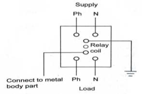
It consists of a relay coil; one end of that coil is connected to the metal body and other to the ground. When voltage on the equipment body rises to 50V (danger level) the current in the relay loop moves the relay contact by disconnecting the supply current and saves from electric shock.
It is mostly commonly used ELCB. It consists of transformer having two primary (neutral and line wire) windings and one secondary winding. In balanced condition there is no current in secondary because the neutral wire balances the current through the phase wire.

During fault a small current flow to ground causing imbalance between line and neutral currents. As a result of which current is induced in secondary winding. The sensing circuit connected to the secondary sends signal to the tripping system and the contact is tripped.
Q4) What are MCCB?
A4) Moulded case circuits breakers are electromechanical devices which protect a circuit from over current and short circuits. They provide over current and short circuits protection for circuits ranging from 63A up to 3000 A. They are used for heavy duty applications as they have high current ratings. They provide electric feeder protection, capacitor bank protection, generator protection, welding applications, low current application that require adjustable trip setting and motor protection.
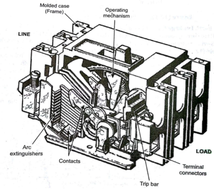
The are made up of heavy duty insulated plastic. MCCB has a bimetallic contact that expands and contacts when there is change in temperature. When current exceeds the adjustable trip value the contact gets heated and expands. The fault currents in MCCB can be interrupted immediately. Whenever a fault occurs, the extremely high current induces a magnetic field in a solenoid coil located inside the breaker – this magnetic induction trips a contact and current it interrupted
Q5) Explain types of wirings?
A5) (i) According to the conductor material used
(a) Copper conductor cables
(b) Aluminium conductor cable
(ii) According to number of cores
(a) Singles core cable (SCC)
(b) Double core or twin core cables (DCC)
(c) Three core cables
(d) four core cables
(e) Two cores with earth continuity conductor cables
(iii) According to type of insulation
(a) Vulcanized Indian rubber (VIR) insulated wires/cables
(b) Tough rubber sheathed (TRS) or cable tyre sheathed (CTS) cables
(c) Polyvinyl chloride (PVC) cables
(b) Lead sheathed cables
(e) Weather proof cables
(f) Flexible cords and cables
(g) XLPE cables
(iv) According to the voltage at which they are manufactured
(a) Low tension (LT) cables – up to 1000V
(b) High tension (HT) cables – up to 11kV
(c) Super tension (ST) cables – from 22-33kV
(d) Extra high tension (EHT) cables – from 33-66kV
(e) Extra super voltage cables – beyond 132 kV
Q6) What is the need for earthing?
A6)
The primary purpose of earthing is to avoid or minimize the danger of electrocution, fire due to earth leakage of current through undesired path and to ensure that the potential of a current carrying conductor does not rise with respect to the earth than its designed insulation.
When the metallic part of electrical appliances (parts that can conduct or allow passage of electric current) comes in contact with a live wire, maybe due to failure of installations or failure in cable insulation, the metal become charged and static charge accumulates on it. If a person touches such a charged metal, the result is a severe shock.
To avoid such instances, the power supply systems and parts of appliances have to be earthed so as to transfer the charge directly to the earth. This is why we need Electrical Earthing or Grounding in electrical installation systems.
i) To protect the operating personnel from the danger of shock.
Ii) To maintain the line voltage constant, under unbalanced load condition.
Iii) To avoid risk of fire due to earth leakage current through unwanted path.
Iv) Protection of the equipment.
v) Protection of large buildings and all machines fed from overhead lines.
Q7) Explain plate earthing and Rod earthing?
A7)
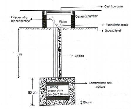
A copper plate of dimension 60cm x 60cm x 3.18 is used for earthing. The plate is buried in ground and layered with coal and salt. Then water is poured to maintain the earth’s electrode resistance below maximum value. The earth wire is bolted to the earth plate.
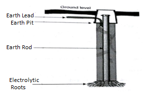
It is similar to pipe earthing method. A copper rod is buried upright in the earth manually or with pneumatic hammer. The length of embedded electrodes in soil reduces earth resistance to a desired level.
Q8) List applications of various types of earthing?
A8)
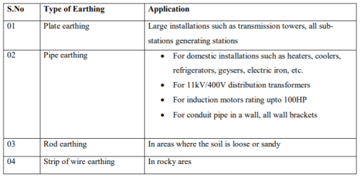
Q9) List the basic steps to be followed for earthing installation?
A9) The usual method of earthing of electric equipments, devices and appliances are as follow:
- First of all, dig a 5x5ft (1.5×1.5m) pit about 20-30ft (6-9 meters) in the ground. (Note that, depth and width depend on the nature and structure of the ground)
- Bury an appropriate (usually 2’ x 2’ x 1/8” (600x600x300 mm) copper plate in that pit in vertical position.
- Tight earth lead through nut bolts from two different places on earth plate.
- Use two earth leads with each earth plate (in case of two earth plates) and tight them.
- To protect the joints from corrosion, put grease around it.
- Collect all the wires in a metallic pipe from the earth electrode(s). Make sure the pipe is 1ft (30cm) above the surface of the ground.
- To maintain the moisture condition around the earth plate, put a 1ft (30cm) layer of powdered charcoal (powdered wood coal) and lime mixture around the earth plate of around the earth plate.
- Use thimble and nut bolts to connect tightly wires to the bed plates of machines. Each machine should be earthed from two different places. The minimum distance between two earth electrodes should be 10 ft (3m).
- Earth continuity conductor which is connected to the body and metallic parts of all installation should be tightly connected to earth lead. Make sure to use the continuity by using continuity test.
- At last (but not least), test the overall earthing system through earth tester. If everything is going about the planning, then fill the pit with soil. The maximum allowable resistance for earthing is 1Ω. If it is more than 1 ohm, then increase the size (not length) of earth lead and earth continuity conductors. Keep the external ends of the pipes open and put the water time to time to maintain the moisture condition around the earth electrode which is important for the better earthing system.
Q10) A consumer uses a 10 kW geezer, a 6 kW electric furnace and five 100 W bulbs for 15 hours. How many units (kWh) of electrical energy have been used?
A10) Given that Load – 1 = 10 kW
Geezer Load – 2 = 6 kW
Electric furnace Load – 3 = 500 watt (five 100 watt bulbs)
Total load = 10kW + 6kW + 0.5kW = 16.5kW
Time taken = 155 hours
Energy consumed = Power in kW × Time in hours = 16.5 × 15 = 247.5 kWh
1 unit = 1kWh.
So, the total energy consumption = 247.5 units If the cost per unit is 2.5, then the total cost of energy consumption ̇=247.5 × 2.5 = 618.75/-
Q11) What is the cost of running a 0.200-kW computer 6.00 h per day for 30.0 d if the cost of electricity is $0.120 per kW⋅h?
A11)
Cost is based on energy consumed; thus, we must find E from E = Pt and then calculate the cost. Because electrical energy is expressed in kW⋅h, at the start of a problem such as this it is convenient to convert the units into kW and hours.
The energy consumed in kW⋅h is
E=Pt=(0.200 kW)(6.00 h/d)(30.0 d)=36.0 kW⋅hE=Pt=(0.200 kW)(6.00 h/d)(30.0 d)=36.0 kW⋅h
And the cost is simply given by
Cost = (36.0 kW ⋅ h)($0.120 per kW ⋅ h) = $4.32 per month.
Q12) What are the basic characteristics of batteries?
A12) The basic characteristics are:
i) Chemistry: Some batteries like lead, nickel and lithium need their own charger. So, the chemistry of the battery is important. It will not be properly charged if exact charger is not used.
Ii) Battery Capacity: It is the charge stored by the battery. y. The battery capacity represents the maximum amount of energy that can be extracted from the battery under certain specified conditions. The energy stored in a battery, called the battery capacity, is measured in either watt-hours (Wh), kilowatt hours (kWh), or ampere-hours (Ahr). The most common measure of battery capacity is Ah, defined as the number of hours for which a battery can provide a current equal to the discharge rate at the nominal voltage of the battery.
Iii) Voltage: Any battery has a nominal voltage. It is important to check the correct nominal voltage before use.
Iv) Cold Cranking Amps(CCA):Every starter battery is marked with cold cranking amps, also abbreviated CCA. The number denotes the amount of amps that the battery is able to provide at -180C.
Q13) What are batteries? List the types of secondary batteries?
A13) It converts chemical energy into electric energy. A combination of two or more voltaic cells is called as battery. Due to chemical reaction inside the cell voltage is produced. Electrodes are immersed in an electrolyte, which forces the electric charge to separate in the form of ions and free electrons.
i) Primary Batteries:
These are basically disposable batteries. They can be used only once. They are not rechargeable. EX. AA, AAA.
Types of Primary Batteries:
(a) Carbon- zinc dry cell: These are AA, AAA. They have zinc electrode as negative electrode and carbon as positive electrode. The output voltage of a single cell is about 1.5 V.
(b) Alkaline cell: It is AA type. It lasts long than carbon-zinc cell. It consists of a zinc anode and manganese dioxide cathode in an alkaline electrolyte
(c) Zinc chloride cell: These are heavy duty cells. It is modified zinc-carbon cell.
(d) Mercury cell: It is not used these days. It consists of zinc anode, mercury compound cathode and potassium or sodium hydroxide electrolyte.
(e) Silver oxide cell: This cell consists of a zinc anode, silver oxide cathode, and potassium of sodium hydroxide electrolyte. Normally used in cameras and watches.
(f) Lithium cell: It is light weight. It offers high output voltage. Two forms of 3V output in widespread use: (a) Lithium-sulfurdioxide(LiSO2 ). (b) Lithium- thionyl chloride.
Ii) Secondary Batteries:
These are rechargeable batteries. These are also called as storage batteries. They are rechargeable because the electric current reverses the chemical reaction inside the batteries that occurred during use. EX used in mobile phones, MP3 players.
Types of Secondary Cells:
(a) Lead-acid cell: It is most commonly used cell. It has porous lead anode and lead-oxide cathode. Used in automobile inverters. The output is of 2.1V.
(b) Nickel cadmium (NiCd) cell: It has Nickel hydroxide anode and cadmium hydroxide cathode. It delivers high current. It is used in cadmium hydroxide electrolyte. Used in alarm systems, TV equipment.
(c) Lithium-ion battery: It has graphite anode and lithium manganese dioxide cathode. The electrolyte used is mixture of lithium salts.
(d) Nickel-metal- hydride (NiMH) cell: They are used in power tools. They only have negative electrode, rest all similar to NiCd cells.
(e) Nickel-iron (Edison) cell: They have Nickel hydroxide anode and iron cathode with potassium hydroxide electrolyte. They are not in use now.
(f) Fuel cell: It converts chemical energy into water and produces electricity. They are used as source of DC power in space program. They are very efficient.
(g) Solar cell: They convert sunlight to electric energy. They are arranged in modules to form an array called solar array. An applied voltage higher than the voltage of one cell can be obtained by connecting cells in series. The total voltage available across the battery of cells is equal to the sum of the individual values for each cell. Parallel cells have the same voltage as one current capacity
Q14) Calculate the electricity bill amount for a month of 31 days, if the following devices are used: 3bulbs of 40W for 6hr, 4 tube-lights of 50W for 8hr and a TV of 120W for 6hr. Given the rate of electricity is Rs.2.50 per unit?
A14) It has been given that the following devices are used as specified 3bulbs of 40W for 6hr, 4 tube-lights of 50W for 8hr and a TV of 120W for 6hr.
Total power consumed by 3 bulbs = 40x3 = 120Wh=0.12kWh
Electrical units for 1 day = 0.12x6=0.72units
Electrical units for 31 days = 0.72 x 31 = 22.32 unis
Total Power the four tube-lights consume in a day = 50x4 = 200Wh=0.2kWh
Electrical units for one day = 0.2 x 8 =1.6 units
Electrical units for 31 days= 1.6 x 31 =49.60 units
Total power the TV consumes in a day = 120x6 =720Wh=0.720kWh
Electrical units for one day = 0.720x6 = 4.32units
Electrical units for 31 days = 4.32x31=133.92units
Total units consumed = Electrical units consumed by bulb for 31 days+ Electrical units consumed by tube-light for 31 days+ Electrical units consumed by TV for 31 days
= 22.32+49.06+133.92
= 205.84units
The rate per unit is given as 2.50 per unit. So, the total bill is = 205.84x2.50 = Rs 514.60
Q15) Calculate the electricity bill amount for a month of April, if 4 bulbs of 40 W for 5 h, 4 tube-lights of 60 W for 5 h, a TV of 100 W for 6 h, a washing machine of 400 W for 3 h are used per day. The cost per unit is Rs 1.80.
A15) Electric energy consumed per day by 4 bulbs = 4x40 x5 = 800Wh
Electric energy consumed per day by 4 lights = 4x60x5 =1200 W-h
Electric energy consumed per day by TV = 100x6 = 600 W-h
Electric energy consumed per day by washing machine = 400x3 =1200 W-h
.’. Total electric energy consumed by all electric appliances = (800+ 1200 + 600+ 1200) W-h = 3800 W-h = 3.8 kWh =3.8 units
Total electric energy consumed in the month of April (30 days) = 3.8 x 30 = 114units
Cost of one unit = Rs. 1.80
Cost of 114 units = 114 x 1.80 =Rs 205.20
Electricity bill amount = Rs 205.20
Q16) A consumer has a maximum demand of 200 kW at 40% load factor. If the tariff is Rs. 100 per kW of maximum demand plus 10 paise per kWh, find the overall cost per kWh?
A16) Units consumed/year = maximum demand x load factor x hours in a year
= (200x0.4) x 8760 = 7,00,800 kWh
Annual charges = Annual M.D charge+ Annual Energy charges
= Rs(100x200+0.1x700800) = Rs. 90,080
Overall cost/kWh = Rs90080/700800 = Rs 0.1285 = 12.85 paise.
Q17) The maximum demand of a consumer is 20 A at 220 V and his total energy consumption is 8760 kWh. If the energy is charged at the rate of 20 paise per unit for 500 hours use of the maximum demand per annum plus 10 paise per unit for additional units, calculate: (i)annual bill (ii) equivalent flat rate.
A17) Let load factor and power factor be unity
Maximum demand = (220x20x1)/1000 = 4.4kW
Units consumed in 500hrs = 4.4 x 500 = 2200kWh
Charges for 2200kWh = Rs 0.2 x 2200 = Rs 440
Remaining Units = 8760-2200 = 6560kWh
Charges for 6560kWh = Rs 0.1 x 6560 =Rs 656
Total annual bill = Rs (440+656) = Rs 1096
Equivalent flat rate = 1096/8760 = Rs 0.125 = 12.5 paise
Q18) What are the basic concepts of household wiring and explain? Basic Concepts of Household?
A18) Wiring up a house electrically can become really easy once we learn few of the fundamental points involved with it. The following simple tips may be memorized by anybody in the field and applied during wiring-up not only small houses but also large houses or apartments: There are basically four components involved in the whole procedure viz.: Power (Mains voltage), load, conductor, and the switch. Normally our domestic mains power includes two paths, the incoming Phase and the outgoing or the return path through the Neutral. Other than these two the third conduction path in an electrical wiring is the “earth" or the ground. Although not required with fixed appliances like lights and fans, this terminal becomes particularly imperative with the AC outlets or the wall sockets. The top pin in a wall socket is where the earth connection is given. The “earthing" is like a huge electrical dumping ground where stray or residual current leakages are absorbed and nullified. The bodies of potentially dangerous appliances like electric irons, geysers, refrigerators, and soldering irons tend to produce electric shock over time on their bodies due to some portion of the phase leakage.
Therefore, these appliances have their bodies connected to their plug’s “earthing" pin which ultimately gets configured with the socket’s earthing terminal once plugged in. It becomes very important that the earthing or grounding connection of every house has optimal absorbing capacity for enabling proper absorption of these appliance body current leakages. If in doubt, consult a qualified electrician and get the main ground source corrected. The path or passage of power from phase to neutral is implemented using conductors or wires and the system constitutes an electrical circuit. However, connecting the phase to neutral directly will cause havoc in the form of a big short circuit and the melting of wires.
Therefore, the right procedure is to connect a load in between these two polarities so that the power flows through the load and operates it, which actually becomes the sole intended purpose of the wiring. But the above procedure will keep the load switched ON permanently, which can become quite undesirable and therefore the introduction of a manually operated circuit breaking or switching device becomes imperative. For this we just need to connect a mechanical switch in line or in series with the load and the phase- that simply solves the issue.
Q19) Explain the various methods of electrical wiring system.
A19) Types of Electrical Wiring Systems
The state electricity board provides the electric supply up to the outside the consumer’s premises. The consumer has to take the connection from that point to the main switchboard at home. From the main switchboard, various types of electrical loads such as fans, lights, room coolers, and refrigerators are connected through the wires. There are different types of wirings used for connecting the loads to the mains which can be used for house electrical wiring as well as industrial electrical wiring. Some of these are discussed below.
Cleat Wiring
In this, porcelain, wood or plastic cleats are fixed to walls or ceilings at regular intervals, i.e., 0.6 m between each cleat. PVC insulated cables are taken through the holes of each cleat and hence cleat support and holds wire. This is an inexpensive method of wiring and is used for temporary installations. Therefore, it is not suitable for home electrical wiring and also it is an outdated method.
Casing and Capping Wiring
In this cable is run through a wood casing having grooves. The wood casing is prepared in such a way that it is of a required fixed length with parallel grooves that accommodates the cables. The wooden casing is fixed to the walls or ceiling with screws. After placing the cables inside the grooves of casing, a wooden cap with grooves is placed on it to cover the cables. This is also a cheap wiring system, but there is a high risk of fire in case of short circuits.
Batten Wiring
In this, insulated wires are run through the straight teak wooden battens. The wooden battens are fixed on the ceilings or walls by plugs and screws. The cables are fitted onto the battens by using tinned brass link clips. These clips are fixed to the battens with rust-resistant nails. This wiring installation is simple and cheap as compared to other electrical wiring systems also takes less time to install. These are mainly used for indoor installations.
Conduit Wiring
In this wiring, PVC cables are taken through either PVC conduit pipes or through steel conduit pipes. This conduit wiring can be either surface conduit wiring or concealed conduit wiring. If the conduit pipes are run on surface of the walls and ceilings, it is called a surface conduit wiring. If the conduits are run inside the surface of the walls and ceilings and are covered with plastering, it is called as concealed conduit wiring.
Surface conduit wiring is used in industries to connect the heavy motors. On the other hand, concealed wiring is the most popular and common method of wiring the residential buildings. The conduit wiring is the safest method of wiring and also looks beautiful (concealed conduit wiring).