Unit - 2
DC Machines
Q1) Explain the process of commutation?
A1) Commutation:
The armature coil has two commutators connected to its ends. When commutators and brushes are in contact current transformation can be attained. In DC machines we use more than one coil. As shown in below figure.
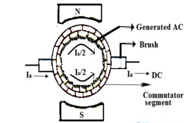
Fig:1 Commutation
Hence, we have more than one pair of commutator segments. The coil is short-circuited for a very short period of time with the help of brushes. This period is known as commutation period.
Reactance voltage: The coil in armature slot has self inductance L. As we already know the direction of current is reversed in commutation. So, due to reversal of current and self-inductance a voltage is induced equal to  . This voltage is also known as Reactance voltage.
Reactance voltage=
Tc= Commutation period.
I is maximum change in current in either direction.
So total change in current = I-(-I)=2I
Reactance voltage=
1.11 is form factor of sinusoidal waveform.
Q2) Describe armature winding and its types?
A2) Armature windings
Simple lap winding –
1) In this type of winding, the back and front pitches are odd and opposite in sign. They have difference of 2 or multiple of 9r.
2) The back and front pitches should be equal to pole pitch.
3) Average pitch, 
4) Commutator pitch, Yc = ±m.
5) Resultant pitch, YR = YB – YF.
6) The number of slots is half the number of coil sides.
7) YB = YF ± 2m (m=1, simplex wave winding)
If YB> YF, YB = YF + 2 (Right handed winding). Yc = +1
If YB< YF, YB = YF – 2 (Left handed winding). Yc = -1.
8) They are useful for low voltage, high current generators.
Simple Wave Winding
1) The back and front pitches both are odd and of same sign.
2) YB and YF are nearly equal to the pole pitches.
3) Resultant pitch, YR = YB + YF
4) Commutator pitch, YC= YA (for lap winding YC = ±1).

5) Average pitch, 
6) The number of coils, 
7) The number of armature parallel paths =2m
m = multiplicity of windings.
8) They are suitable for low current and high voltage generators.
9) It gives more emf than lap winding.
Q3) The armature winding of a 6-pole 250V dc shunt motor is lap connected. There are 100 slots, each slot containing 8 conductors. The flux per pole is 20mW and current taken by the motor is 25A. The resistance of armature and field circuit are 0.1 and 125ohm. If rotational losses are 800W find.i)gross torque ii) useful torque
A3) Ish=250/125=2A
Ia=25-2=23A
Eb=250-(23x0.1)=247.7V
Eb=
247.7=
 )
)
N=928.87rpm
i) Gross torque Ta=9.55  =9.55x
 58.57N-m
Ii) Cu loss in armature= 232 x 0.1=53W
Shunt Cu loss=250x2=500W
Rotational Losses=800
Total motor loss=800+500+53=1353W
Motor input=250x25=6250W
Motor output=6250-1353=4877W
Tsh=9.55 x  = 9.55x
  =50.14 N-m
Iii) Efficiency =  =
=  = 0.78= 78%
Q4) A 230V shunt motor on no load runs at 1000rpm and takes 5A. Armature and shun field resistances are 0.3 and 250ohm. Calculate the speed when load taking a current of 50A. The armature reaction weakens the field by 4%.
A4) Ish= 230/250=0.92A
Ia1=5-0.92=4.08A
Ia2=50-0.92=49.08A
Eb1=230-(4.08 x 0.3) =228.776V
Eb2=230-(49.08 x 0.3) =215.276V
 =
= =940.99rpm
Q5) A 6-pole, 440V wave connected shunt motor has 1000armature conductors and flux/pole of 20mWb. The armature and field resistances are 0.4 and 250ohm. What will be the speed and torque developed by the motor when it draws 20A from supply? If magnetic and mechanical losses are 850W. Find i) useful torque ii) output in kW
A5) The useful torque is given by Tsh=9.55 x 
Ta=
Ish=440/250=1.76A
Ia=20-1.76=18.24A
Eb=440- (18.24 x 0.4) = 432.70V
But we already know Eb=
432.70 =
N= 432.70 rpm
Ta= =
= =174.19 N-m
Ii) For output we need Motor input and total losses
Armature Cu loss = 18.242 x 0.4=133.08W
Field Cu loss = 440 x 1.76=774.4W
Iron and Friction loss= 850W
TOTAL LOSS= 133.08 + 774.4 + 850= 1757.48W
Motor input= 440 x 20=8800 W
Output = 8800-1757.48=7042.52W
Tsh=9.55 x  =9.55 x
  = 155.43 N-m
Q6) A 250V dc shunt motor has an armature resistance of 0.4ohm and field resistance of 250ohm. When driving a load of constant torque at 700rpm, the armature current is 20A. If it is desired to raise the speed from 550 to 650rpm, what resistance should be inserted in the shunt field circuit.
A6) As we already know
 =
=  (1)
(1)
The torque relation is given as
Ta α  Ia
Ia
For load with constant torque we can say
 Ia2 α
Ia2 α  Ia1
Ia1
Ia2 = Ia1 x  = Ia1 x
Ish1= 250/250 = 1A
Ish2= 250/Rt
Rt= Total resistance of shunt field circuit
Ia2= 20 x 
But we also that Eb1= 250- (20 x 0.4) =242V
Eb2 = 250- ( =250-
=250-
From the equation 1 above
 =
=  x
x 
55 – 343.75 x
  + 98.3 x
  = 0
= 0
Solving above equation we get
 =300.4Ω
The value of addition shunt resistance required will be 300.5 – 250=50.5Ω
Q7) A 250V shunt motor has an armature resistance of 0.5 ohm and takes an armature current of 35A on a certain load. What amount the main flux will reduce to raise the speed by 50% if torque is constant.
A7) As we already know
 =
= 
 Ia2 α
Ia2 α  Ia1
Ia1
Ia2 = Ia1 x 
Eb1= 250- (35 x 0.5) = 232.5V
Eb2= 250- (35k x 0.5)
Let 
As we need to raise the speed by 50% then  =
= 
Substituting in above equation we get
 =
=  x k
x k
35k2-500k + 697.5=0
K = 1.56
The other value of k does not hold for this question.
 =1.56
=1.56
So, the percentage reduction in the main flux will be given as

 = 35.89%
Q8) What are the causes of bad commutation. Suggest the remedies.
A8) By saying bad commutation, we only mean Sparking and burning while commutation. It can occur because of following reasons:
1.When Brushes position is not proper.
2. When spaces between brushes is not proper. This may be checked by marking an adding-machine tape around the commutator.
3. Mica should be between bars undercut about 0.063 in below the commutating surface.
4.When commutator is not ground, resulting in rough or burned commutator. Rough or burned commutator.
5. Grooved commutator. This may be prevented by properly staggering the brush sets so that the spaces between the brushes of an arm are covered by brushes of the same polarity of other arms.
6.When it has poor brush contact. It may be due to improper fitting of brush to commutator surface.
7.The brushes are not replaced correctly, i.e of same size or grade.
8.When the brushes do not move freely in their holder, irregularity occurs. This is called sticking brushes.
9.When operated for current density below 35A/in2,may lead to chattering of brushes. This can be corrected by lifting brushes to raise density
10. Due to poor line up or inadequate foundation Vibration occur.
11.The Short-circuited turns on the commutating or compensating fields can be the reason for bad commutation.
12. Because of open or very high resistance joints between the commutator neck and the coil leads can lead to the burning of bar at the bad joint.
13. A broken coil conductor produces an effect similar to that produced by the poor joints. In case of emergency the open coil may be opened at both ends, insulated from the circuit, and a jumper placed across the two affected necks.
14.With the resulting unbalanced air-gap fluxes under the poles, large circulating currents must be expected even with good armature cross connections.
15. Overloading.
Remedies:
There are basically three methods of improving commutation.
i)Resistance Commutation
Ii)Voltage Commutation
Iii)Compensation Windings
Below are explained briefly the methods of improving commutation
i)Resistance Commutation: The Resistance Commutation can be obtained by replacing low resistance copper brushes with high resistance carbon brushes. The use of Carbon brushes makes the contact resistance between commutator segments and brushes high. This high contact resistance has the tendency to force the current in the short-circuited coil to change according to the commutation requirements.
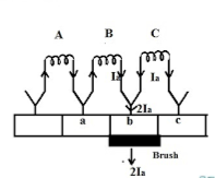
Fig 2: Resistance commutation
As seen from figure above Ia from the coil C cab reach brushes from two paths in commutation period. One path is direct through the commutator segment b and to the brush and the 2nd path is first through the short-circuit coil B and then through the commutator segment a and to the brush. The second path is shorter. When we use high resistance brushes then the contact area of brush with B decreases and contact area with A increases. But the resistance is inversely proportional to the contact area. So, Ra will decrease and Rb will increase according to the movement of brush.
Ii)Voltage Commutation: This method has two ways to improve commutation
a) Brush Shift
b) Commutating poles or interpoles.
In this method a voltage is induced in the coil undergoing commutation. This will help to neutralise the reactance voltage. The both voltages are opposing each other. So when injected and reactance voltages are equal, the direction of current in short circuited coil reverses, helping to attain sparkles commutation.
a) Brush Shift: The effect of armature reaction is to shift the magnetic neutral axis (MNA) in the direction of rotation for the generator and against the direction of rotation for the motor. Armature reaction establishes a flux in the neutral zone. A small voltage is induced in the commutating coil since it is cutting the flux.
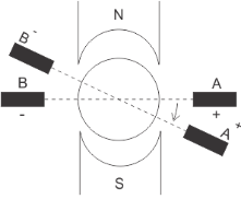
Fig 3: Brush Shift
b) Interpoles: The main function of interpoles is to induce an emf which is equal and opposite to that of reactance emf, which makes commutation sparkles. They also neutralize the cross magnetizing effect of armature reaction.
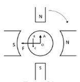
Fig 4: Interpoles
In above figure OF=MMF due to main poles.
OA=Cross Magnetizing MMF due to armature
BC= MMF due to interpoles.
BC is in opposition to OA. Hence it helps to cancel cross magnetization due to OA.
The ampere turns needed to cancel armature reaction ampere turn and to create the required flux is given as
ATi=ATa(peak)+
Bi=Flux density in interpole air gap
 =air gap of interpoles
Q9) A 220V dc shunt motor has an armature resistance of 0.25ohm and runs at 900rpm. With armature current of 40A. The speed to 700rpm is required. If armature resistance remains same, find the additional resistance to be connected in series with the armature.
A9) Eb= 220 - (40 x 0.25) =210V
As the armature current does not change then Eb  Speed
Speed
220  900
900
So, for speed to be 700
Eb1  700
700
Eb1 = [700/800] x 220=192.5V
The additional resistance required will be
220 – (R+0.25) x 40=192.5
R= 0.44Ω
Q10) A 230V shunt motor with armature resistance of 0.4 ohm runs at 550rpm on full load and takes an armature current of 20A. If resistance of 1ohm is placed in the armature circuit. Find full load torque.
A10) We already know that  =
= 
But as flux is constant  =
= 
 = 230-(0.4 x 20) = 222V
T α φ Ia
As flux is constant T α Ia

But  =
=  and
and  =20A
=20A
Eb2= 230 - [20 x (0.5+1)] = 200V
Now the speed at full load torque is
 =
= 
N2 = x 550 = 478.26rpm
Q11) A series motor is running on a 400V circuit with a regulating resistance of R ohm. The total resistance of armature and field coil is 0.3 ohm. On certain load with R=0, the current is 18A and speed is 1000rpm. With another load and R=3 ohm the current is 12A. Find new speed, when field strength at 12A is 80% of that 18A.
A11) Eb1= 400 – (18 x 0.3) = 394.6V
Eb2= 400- [12 x (0.3+4)] = 348.4V
As the field at 18A is 60% of that at 12A. Hence, we can write
 = 0.6
= 0.6 
 =
= 
N2 = 1000 x  = 1472 rpm
Q12) A 220V DC Shunt motor runs at 450rpm when armature current is 39A. Calculate speed if the torque is doubled. The armature has a resistance of 0.2 ohm?
A12) Ta α φIa
Ta1 α φIa1 and Ta2 α φIa2
2= Ia2/39
Ia2=78A
N2/N1=Eb2/Eb1
Eb1=220-(39x0.2)=212.2Volts
Eb2=220-(78x0.2)=204.4Volts
N2/450=204.4/212.2
N2=433.46 rpm
Q13) Explain in detail armature reaction?
A13) When armature of a DC Machine carries current, the distributed armature winding produces its own mmf which is known as armature reaction. The figure is shown below.
The nature of armature reaction in a DC machine is cross magnetizing with its axis along the (90° to main pole).
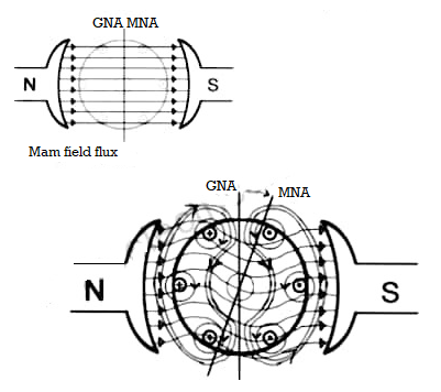
MNA (Magnetic Neutral Axis) It is the axis along which no EMF generated in the armature conductors.
GNA (Geometrical Neutral Axis) It is perpendicular to the field axis.
When DC machine is running the flux due to armature and field winding exists. The armature flux is dominant on the later and hence disturbing the main field flux. This effect is called armature reaction in DC machines.
Q14) A 230V DC Shunt motor takes 4A at no load when running at 600 rpm. The field resistance is 100 ohm. The resistance of armature at standstill gives a drop of 6V across armature terminals when 10A were passed through it. Find i)Speed at no load (ii) Torque. Normal input of motor is 6kW
A14)
i)Speed 
Ish=  =2.3A
=2.3A
F.L Power=6000
F.L line current=  =26.08A
Ia=26.08-2.3=23.78A
Ra= =0.6Ω
=0.6Ω


N=566.2 rpm
Ii)Torque Ta=
 =
=

Q15) Explain Air gap flux density distribution with armature reaction.
A15) From the figure(a) below we can say For one pole pair with brushes placed in GNA which is also the MNA, when armature is not carrying current. In figure(b) the armature mmf distribution is shown. It is clearly seen that the armature mmf is stepped wave of 90 from d-axis. Which means its cross magnetizing. The step wave can be approximated as a triangular wave. The armature ampere turns will be
Ampere conductors/pole=ZIc/P=ZIa/AP
Ic=conductor current
Ampere turns/pole=ZIa/2AP=ATa(Peak)
ATa(peak)= ATa(Total)/P
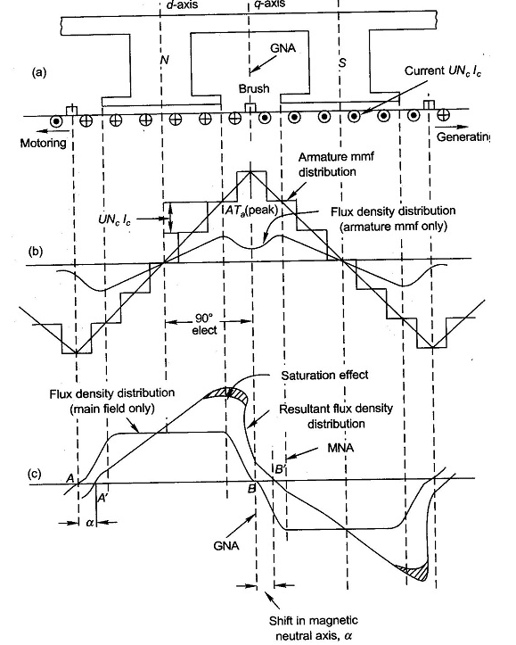
Fig 5. Armature Reaction
The flux density shown in figure(b) has a dip in q-axis because of large air gap in the inter-pole region. The Flux density of main field and the resultant flux density both are shown in figure(c). Where we can se that the armature reaction mmf distorts the flux density wave.so as to be depressed in one half of the pole and strengthen equally in other half. This is because of the odd symmetry with d-axis of the flux density wave of armature mmf. Due to this the flux/pole remains constant although the resultant flux density wave is distorted. The figure also shows that its MNA also gets shifted from its GNA by small angle α so that the brushes placed in GNA are no longer in MNA.
The armature reaction in DC machines is cross magnetizing causing distortion in flux density wave and slightly shifts MNA. It also causes demagnetization. Distortion in flux density distribution results in increase of flux density on one pole and decrease on other. Distortion also has adverse effect on commutation but can be solved by interpoles.
Q16) An 8 pole DC shunt generator with 730 wave connected armature conductor s and running at 500 rpm supplies a load of 11.5Ω resistance at terminal voltage of 250v. The armature resistance is 0.3Ω and field resistance of 235Ω. Find armature current and induced emf.
A16) Load current = V/R = 250/11.5 =21.74A
Shunt current = 250/235 =1.064A
Armature current = 21.74+1.064 = 22.8A
Induced emf = 250 + (22.84 x 0.3) = 256.8V
Q17) A short shunt DC compound generator supplies 210 A at 100v the resistance of armature, series field and shunt field windings are 0.05Ω, 0.03Ω and 50Ω respectively. Find EMF generated.
A17) For short shunt connection armature terminal voltage Va = 100+ (210x0.03) =106.3V
Shunt field current = 106.3/50 = 2.13A
Armature current =210+2.13 =212.13A
Induced emf = 106.30 + (212.13 x 0.05) = 116.9V
Q18) The speed of a 37.3kW series motor working on 500V supply is 600 rpm at full load and 90% efficiency. If the load torque is made 250 N-m and a 5ohm resistance is connected in series with the machine, calculate the speed at which the machine will run. Assume armature and field resistance of 0.5ohm?
A18) Load torque in first case T1=37300/2 (600/60)=593.65 N-m
Input current Ia1=37300/0.9*500=82.9A
T2=250 N-m. So, finding Ia2
For series motor T α φ Ia α Ia2
T1 α  and T2 α

 =82.9*
 =53.79A
Eb1=500-(82.9*0.5)=458.5V
Eb2=500-53.79(5+0.5)=204.11V


Q19) The armature of a four pole DC shunt generator is lap wound and generates 210v when running at 500 rpm. Armature has 132 slots, with 6 conductors/slot. If armature is rewound, wave connected, find EMF generated with same flux/pole running at 300rpm.
A19) Total conductors Z = 132x6= 792
The emf E= 
For lap winding P=A
E= 
210= x 792 x 500/60
 = 31.82mWb
If wave connected number of parallel paths = 2
The emf E=  = (31.82x10-3 x 792 x 300/60) (4/2)
E= 252V
Q20) A 15kW 400V 350rpm dc shunt motor has current 30A at full load. The moment of inertia of rotating system is 6.5kg-m2. The starting current be 1.2 times of full load current. Find the full load torque?
A20) Full load output = 15000W
Speed N=350rpm=5.83rps
Output = Tω
T = 15000/2 x5.83 = 409.3N-m
Q21) A DC series motor operates at 600 rpm with line current of 110A from 220v main. It’s armature resistance is 0.2Ω and field resistance is 0.1ohm Find the speed at which motor runs at a line current of 25A, given flux at this current is 45% of flux at 110A.
A21) 
 = 0.45
E1=220 – (0.2+0.1) x 110=187V
E2=220 – (0.2+0.1) x 25 = 212.5V

N2= 1515.15rpm
Q22) A belt driven,120kWshunt generator running at 310 rpm on 220v busbars continues to run as a motor when the belt breaks, then taking 10kW. What will be its speed with armature resistance of 0.03 Ω field resistance of 60Ω and contact drop under each brush is 1v.
A22) Input current = 120x1000/220 = 545.45A
Shunt current Ish= 220/60 = 3.67A
Armature current Ia= 545.5-3.67=541.83A
E2= 220 – (541.83 x 0.03)- 2x1[drop across brush]
E2=205.74V
The armature current Ia now becomes Ia= 545.5+3.67= 549.17A
As the system here runs as a generator.
E1= 220 – (549.17 x 0.03) +1x2 = 201.5V

As shunt current is constant so  =
= 


N2= 316.5rpm
Q23) The input to 230v DC shunt motor is 12kW. Calculate the torque developed, efficiency. No load current=6A, No load speed=1200rpm armature resistance=0.5Ω, shunt field resistance= 110Ω.
A23) No load input =230x6=1380W
Ish=230/110 =2.1A
Armature current at no load = 6-2.1 = 3.9A
No load armature Cu loss= 3.92 x 0.5= 7.6W
Constant losses = 1380 – 7.6 = 1372.4W
When input is 12kW
Input current = 12000/230 = 52.17A
Armature current = 52.17 – 2.1=50.07A
Armature Cu loss = 50.072 x 0.5 =1253.69W
Total loss=1253.69+1372.4=2626.09W
Output= 12000-2626.09 =9373.9W
Efficiency = 9373.9/12000=0.781=78.1%
Q24) A 230v DC series motor is running at a speed of 550rpm and draws 50A. Calculate at what speed the motor will run when developing half the torque. Total resistance of armature and field is 0.08Ω.
A24)  =
=
Ta α φIa
Ta α 
 )2
)2
 )2
)2
Ia2 = 50x0.707=35.35A
E1=230- (50x0.08) =226V
E2=230- (35.35x0.08) =227.17V
 =
=
 =
=
N2= 781.97rpm
Q25) A 230v shunt motor has an armature resistance of 0.3Ω and field resistance of 140Ω. The motor draws 5A at 1600rpm at no load. Calculate the speed of motor?
A25) Ish= 230/140= 1.643A
Ia1=5-1.643=3.36A
Ia2=50-1.643=48.36A
E1= 230- (3.36x0.3) =226.34V
E2= 230- (48.36x0.3) =215.5V
 =
=
 =
=
N2= 1523.37rpm
Q26) A DC series motor drives a load, the torque if which varies as the square of the speed. Assuming magnetic circuit to remain unsaturated and negligible motor resistance. Calculate the reduction in motor terminal voltage which will reduce the motor speed half the value it has on full load.
A26) Ta α φIa
Ta α 
Ta α 
N2 α 
 =
=
 =
=
Let V1 and V2 be voltage across motor in two cases.
E1=V1 and E2=V2
 αIa1
αIa1
 =
=

 x 2
x 2
 =
= 
% reduction in voltage = V1-V2/V1 x 100 = 4-1/4 x100 = 75%
% change in motor current = Ia1-Ia2/Ia1 x 100 = 50%
Q27) What is critical resistance and critical speed of DC shunt generator.
A27) If the field resistance is increased to OA, then Field Resistance line intersect the OCC curve at point p, and hence there will not be voltage build up beyond point p.
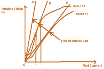
Fig 6: Critical Resistance
Now, if shunt field resistance is such that OB represents the Field resistance line then as clear from the figure above, the lone is intersecting the OCC curve at many points between q and r, therefore the field current will fluctuate between s and t and hence the voltage generated at the terminals of DC Shunt Generator will vary from qs to rt resulting in unstable condition. If we find the slope (tanƟ) of the Field Resistance Line then we will get Field Resistance value which is known as Critical Filed Resistance. Here Critical Field Resistance = tanƟ = qs/Os
As clear from the figure above, if the field resistance is more than the Critical Field Resistance then there will not be voltage build up in DC Shunt Generator. See in the figure OA is shunt field resistance which is more than Critical Field Resistance OB (check by slope, slope of OA is more than slope of OB), hence there is no voltage build up in DC Shunt Generator.
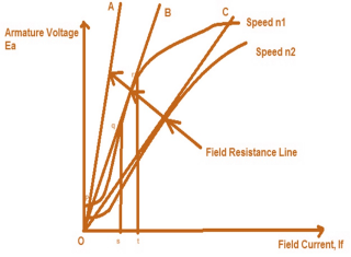
Fig 7: Armature voltage v/s Field Current
Suppose the field resistance is OC and DC Shunt Generator is running at a speed of n1 for which the stable point of its terminal voltage is C. Now the speed of DC Shunt Generator is reduced to n2 therefore the OCC curve will also move downward as shown in figure. It should be noted here that the same field resistance line OC is now tangent to the new OCC curve and therefore will create an unstable condition of operation of DC Shunt Generator. This speed n2 is hence called Critical Speed.