Unit - 4
Three Phase Transformers
Q1) Explain in detail the working of 3 winding transformer.
A1) As the name suggests this transformer can be made by adding one additional winding. The main use of this type of transformer is for interconnections with the transmission line at various voltages, for measuring voltages of an H.V side transformer, synchronous condensers can be connected to this winding to inject reactive power in system for voltage control. Below is shown the figure which explains how the tertiary winding can be used for stabilization.

Figure: Tertiary winding for stabilization
The unbalanced load cab be divided into three phase sets i.e. positive, negative and zero sequence component. The star-star connection unbalanced load provides high reactance between line and neutral. The zero-sequence current component on secondary side cannot be balanced by primary current and hence magnetic flux is developed on the secondary side. Then the delta connected tertiary allows the circulation of zero-sequence current in it, as shown in the above figure. The equivalent circuit of the three winding transformer is shown below. There are three terminals primary (1), secondary (2), and tertiary (3) and one common terminal, neglecting the exciting current.
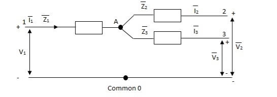
Figure: Single phase equivalent circuit of three winding transformer
The impedance can be calculated by the short circuit test. If  is the short circuit impedance of winding 1 and 2 with winding 3 open, then we can write
 =
=  +
+


The above three equations can also be written as


The core loss, magnetizing loss and turn ratio can be determined by open circuit test on any one of the three windings.
Q2) List the advantages and uses of open delta connection.
A2) If only two transformers are used and 3-Ø supply is connected to the primaries as shown below in figure, then three equal 3-Ø voltage will be available at the secondary terminal on no-load.
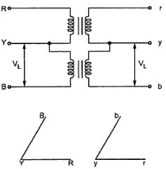
Fig: V-V connection
As one transformer is removed, then the total load carried by V-V bank is not 2/3 of the capacity of Δ-Δ bank but only 57.7% of it. The reduction is of 15% from normal rating.
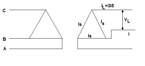
Fig: Closed Δ
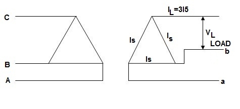
Fig: Open Δ
Now from above figure we can mathematically prove that the capacity is 1/ for this connection.
For closed Δ:
Δ-Δ capacity =  VLIL =
  VL(
VL( IS)
IS)
= 3VLIS
For open Δ:
V-V capacity =  VLIL =
  VLIS
VLIS

= 
Uses:
1) When three phase load is too small for the installation of full 3-Ø transformer.
2) When any one of the transformer in Δ-Δ is disabled.
3) When it is found that in near future can increases the change of closing of open delta.
Disadvantage:
1) The average p.f at which the V-bank operate is less than that of the load.
2) If the load is balanced than also the secondary terminal voltage lend to become unbalanced.
Q3) What is polarity test of transformer?
A3) The polarity test of a transformer can be done by measuring only voltage at no load. The basic connections are shown in below circuit.
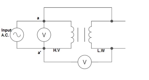
Fig: polarity Test
From above circuit input is applied for one winding. There is another voltage ‘V’ measured between one winding from each terminal. If voltage V’ > V, polarity is additive. If voltage V’ < V, polarity is subtractive.
Q4) Explain parallel operation of 3-Φ transformer
A4)
- The voltage ratio must refer to the terminal voltage of primary and secondary.
- The phase displacement between primary and secondary voltages must be same for all transformers.
- The phase sequence must be same.
- All three transformers in 3-Ø transformer bank will be of same construction.
Q5) Two transformers are required for a Scott connection operating from 410 V 3-Ø supply for supplying two 1-Ø furnaces at 200 V on the two-phase side. If total output is 130 kVA, calculate secondary to primary turn ratio and the winding of each transformer?
A5) For main Transformer
Primary voltage = 410 V
Secondary voltage = 200 V

Secondary current =  = 325 A
Primary current = 325 × 
= 153.54 A
For teaser Transformer
Primary volts =  = 355 V
Secondary volts = 200 V

Q6) A delta-delta bank consisting of three 10kVA,2200/220v transformer supplies a load of 40kVA. If one transformer is removed, find the resulting V-V connection. Find total kVA rating of V-V bank and ratio of V-V bank to delta-delta transformer rating?
A6) kVA rating of V-V bank = 2x10x0.866 = 17.32kVA
 =
=  = 0.577 = 57.7%
Q7) A delta-delta bank consisting of three 10kVA,2200/220v transformer supplies a load of 40kVA. If one transformer is removed, find the resulting V-V connection. a) kVA load carried by each transformer b)% of rated load carried by each transformer.
A7) As we already know  =
=  3
3
KVA load supplied by each transformer = 40/ 3 = 23.1kVA
% of rated load =  = 23.1/10 = 231 %
Q8) Two transformer connected in open delta supply a 430kVA balanced load operating at 0.9 p.f lagging. The load voltage is 460v. What is the kVA supplied by each transformer?
A8) kVA of each transformer = (430/2)/0.9 = 238.9kVA
The p.f of two transformers will be cos (30 -φ) and cos(30
 +φ)
+φ)
Cos φ=0.9
φ = 25.8
P1= kVA cos (30 -φ) = 238.9 x cos (30
 -25.8
-25.8 ) = 238.27kW
P2= kVA cos (30 +φ) = 238.9 x cos (30
 + 25.8
 ) =134.28kW
Q9) Two, 1-Φ furnaces working at 110v are connected to 3000v, 3-Φ mains through Scott connected transformer. Calculate the line current in 3-Φ mains when the power taken by each furnace is 400 kW at a p.f of 0.8 lagging. Transformer has no losses.
A9) K= 110/3000 = 0.0367
I2=400000/0.8x110 = 4545.5A
The 3-phase side is balanced as the load is balanced.
The primary phase current = 1.15kI2 = 1.15 x 0.0367 x 4545.5=191.84A
For star connection Iph=IL
IL= 191.84A
Q10) Two 1-Ø transformers, one of 800 kVA and 400 kVA are connected in parallel to the same bus bars on primary side. Their no load secondary voltage 500 V and 510 V respectively. The impedance voltage of first is 8% and that of second is 5%. Assume ratio of resistance to reactance is same and equal to 0.4 in each. Calculate the cross current when secondary’s are connected in parallel?
A10) The X/R is same for both; hence they do not have any phase difference.
Let secondary be 480 V
For full load IA = 800 ×  A
A
IB = 400 ×  A
A
ZA = 
ZB = 
The cross current is given as
IC =  A
A
Q11) Explain Scott connection of transformer
A11) For making 3-Ø to 3-Ø transformation from two transformers we use this connection.
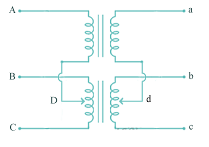
Fig: Scott Connection
- The above figure shows that the centres of one transformer are tap, and has 0.866 tap and is known as Leaser Transformer.
- One ends of both the primary and secondary of Leaser transformer are joined to centre tap on both primary and secondary of main transformer.
- There is one transformer having its centre taps on both primary and secondary and is known as main transformer.
The voltage diagram is shown below
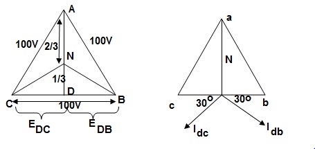
Fig: Voltage and Phase diagram
- EDC and EDB are each 50 V and 180˚ out of phase because coils DB & DC are on same circuit but in opposition.
- EDA is equal to 86.6 V
 and lags behind the voltage across main by 90˚.
 - Idb lags behind voltage Edb by 30˚ and Idc leads Edc by 30˚.
- The teaser transformer and each half of the main transformer all operate at different power factors.
- Full rating of transformer is not utilized. The teaser transformer operate at 0.866 of its rated value and main transformer coil operates at cos 30˚ = 0.866 p.f
Q12) Explain Star-star connections of three phase transformer.
A12) The below figure shows transformers connected in Y/Y on both primary and secondary sides. The ratio of line voltage and transformation ratio of line voltage and transformation ratio of both primary and secondary of each transformer in same. Hence the phase voltage VP =  . VLine (line voltage)
This connection works only if the load is balanced.
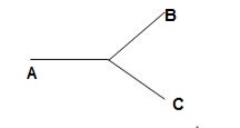
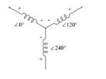
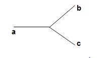
Fig: Three phase transformer Y-Y connection
- The effect of unbalanced load can be balanced by placing single load between a and n on secondary.
- Power to load is supplied by primary side A.
- As, A is in series with B and C and has b and c open on secondary, so it cannot supply required power.
- Now, B and C acts as high impedance in this condition, allowing very less flow of current in A.
- A low resistance can be connected between a and n which is approaching to short circuit. So, small current flows.
- Hence, EAN will reduce to zero but EBN and ECN will rise to full primary line voltage.
- The above shown connection is most economical for small, high-voltage transformers because the number of turns per phase and the amount of installation required is minimum.
- One more advantage is that the installation is stressed to the extent of line to neutral voltage i.e. 58% of line voltage.
- For having a sine wave voltage at output, it is necessary that sine wave of flux should be in the core. To fulfil this, we require third harmonic component of exciting current.
- To attain this if primary neutral is isolated then triple current cannot be attained. So, the best way is to provide a territory winding to each transformer of 1000 kVA rating.