Unit - 2
Electrostatic fields
Q1) Two insulated charged copper spheres A and B half their centres separated by a distance of 50 cm. What is the mutual force of repulsion if charge on each is  coulomb. The radii of A and B is negligible compared to distance of separation.
B) What is the force of repulsion of each sphere is charged double of the above amount and the distance between them is halved?
A1) 


B) 


Q1) The electrostatic force on a small sphere of charge 0.4μc due to another small sphere of charge -0.8μc in air is 0.2 N.
(a) What is the distance between the two spheres?
(b) What is the force on the second sphere due to the first?
A2) Here,


B) Force on second sphere is same 0.2N=F
Q2) A point charge of 2.0 μc is at the centre of a cubic Gaussian surface 90 cm on edge. What is the electric flux through the surface?
A3) Here q= 20 μc=2×
L=90 cm
 =
= 

Q3) Consider uniform electric field E, 
Field is along positive x direction
Surface area =
(a)What is the flux of this field through a square of 10 cm on a side whose plane is parallel to y z plane?
(b)What is the flux through the same square is the normal to its plane 30 degree angle with x axis?
A4) (a) When plane is parallel to y z plane


(b)When normal to the plane makes an angle of 30 degree with x-axis then  =30°
=30°


Q4) Two particles having charges  and
and  coulombs are spaced 0.8 metre apart. Determine the electric field at a point A situated at a distance of 0.5 metre from each of the particles.
A5) Let the two particles have charge  coulombs then the point A will be as shown in (1). Let the origin of the three axis be located at the point charge
  then the coordinates of
  will be (0,0) (0.8,0) respectively.


Differentiating partially with respect to x and y we get


For the location of point A
x=0.4 and y=  =0.3
=0.3
Substituting these values we have


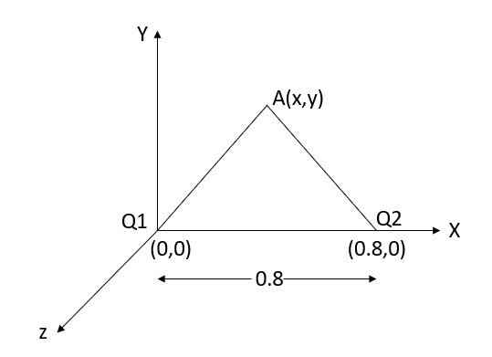


Since the field is desired in xy plane
 and field intensity E is given by

Substituting the values of  and
and  we get

Q5) Determine the electric intensity at a point A located at a distance of 0.3 metre and 0.4 metre respectively from charges  spaced 0.5 metre apart.
  has to charge
  coulombs while
  coulombs.
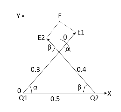
A6) Let the electric intensity is due to  be
be  respectively and let the origin be located at
  as shown in figure (2). Then the angle
  will be 90°.
The magnitude of the individual intensities from equation will be


In order to add these intensities vectorially, thin components along x and y direction will be used.
(i) The x component of 

(ii) The x component of 

(iii) The y components of 

(iv) The y component of 

The total x components of  let us say
  will be

And the total y component of E let us say  will be

Resultant electric intensity has a magnitude E=


Q6) Derive an expression for the potential difference at any point between spherical shells in terms of applied potential using Laplace Equation.
A7) Since the medium between shells is uncharged, Laplace Equation can be applied. In spherical coordinates lapis equation is given by

By symmetry the field and therefore the potential function depends upon the radial distance r alone
Therefore,


Integrating we have


Integrating again

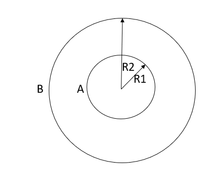
If the radius of spherical shells A and B are  and R and v is the voltage we have
When, 

Substituting these values in equation (1)


Solving these two equation for 


Substituting values of 


Q7) A positive charge of  coulombs per cubic metre occupies the volume of sphere. At point in the inferior at a distance r from the centre, a small proverb charge of +2 is inserted. What is the force acting on the probe charge?
A8) Force P on the probe charge at a point P lying at t a distance r from the centre, as shown in fig.

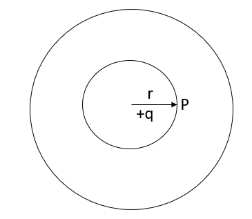
Figure: A small probe charge +2 inserted at a distance r from the centre
On applying Gaussian law will yield

But the surface of sphere 
Therefore, 
While the volume of a sphere is 

Putting these values in above equation we get

We know that,


Putting this value of E in  we get

Q8) Using Laplace Equation, determine the field intensity over a gap between coaxial cylinders.
A9) Let the inner and outer radius of the coaxial cylinder be  respectively as shown in figure. We have to determine the field within the coaxial cylinder subject to boundary condition.


Since the nature of boundaries are of cylindrical nature, writing Laplace Equation in cylindrical form

If the cable is long, then except near ends there will be no variation with z. Father because of cylindrical symmetry potential cannot be a function of  so equation reduces to

Integrating the differential equation twice we have

Where  are constants of integration and can be evaluated from the boundary conditions
Thus, 


Solving above two equations we have

Putting these values of  and
and  above
above


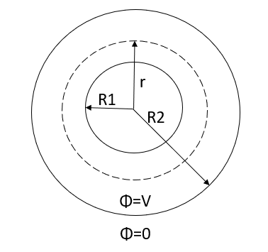
Figure: Cross section of coaxial cylinder
Q9) A point charges 1,-2,-3 and 3μc are located on the x-axis at x=1,2,3 and 4 meter respectively. What energy is stored in the field.
A10) Energy stored=
Let us find out the potential V using equation.


Hence energy stored in the field is zero.
Q10) A radio antenna 1 cm diameter conductor is stretched horizontally 10 metre above the ground. Determine the capacitance of the antenna per unit length. Neglect the end effects and consider the ground to be perfect.
A11) h= 10 metres


 farad
farad

 p farad

Q11) A 2 μF capacitor is charged by connecting it across a 100 V DC supply is now disconnected and the capacitor connected across another 2 μF capacitor. Assuming no leakage, determine the potential difference between the plates of each capacitor and energy connected on amount of energy stored as 2 cases.
A12) When the capacitor is connected across a 100 V D.C energy stored  is given by


Now with 100 v supply this capacitor is charged and charge capacitor is charged and charge Q accumulated on 2 μF capacitor is


Where 100 v D.C supply is replaced by another capacitor of 2 μF. The charge  coulombs gets redistributed to a common potential V such that


Energy stored  is given by

Loss of energy=
Q12) When a charge distribution is placed over an infinite ground plane Coulomb’s law and Gauss’s law cannot be readily applied. Exaplian how to overcome this drawback?
A13) It is a very powerful technique for solving electrostatics problems involving charges and conductors.
When a charge distribution is placed over an infinite ground plane Coulomb’s law and Gauss’s law cannot be readily applied.
Solving Poisson’s or Laplace’s equation is an option, but this is also mathematically challenging, likely to require a numerical solution
It turns out that an electrically equivalent problem can be created using the image distribution with the ground plane removed.
A simple example of a single point charge Q distanced above a ground plane is shown in Figure.

Figure: Electric field lines
Consider a point charge q held as a distance d above an infinite grounded conducting plane as shown in Figure The electrostatic potential of this system must satisfy the following two boundary conditions:
V(x,y,z) =0
 A direct calculation of the electrostatic potential cannot be carried out since the charge distribution on the grounded conductor is unknown.
Note: the charge distribution on the surface of a grounded conductor does not need to be zero.
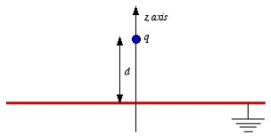
Figure: Method of images
Consider a second system, consisting of two point charges with charges +q and -q, located at z = d and z = -d, respectively as shown in figure. The electrostatic potential generated by these two charges can be calculated directly at any point in space. At a point P = (x, y, 0) on the xy plane the electrostatic potential is equal to

Since this solution satisfies the boundary conditions, it must be the correct solution in the region z > 0 for the system shown in Figure. This technique of using image charges to obtain the electrostatic potential in some region of space is called the method of images.
The electrostatic potential can be used to calculate the charge distribution on the grounded conductor. Since the electric field inside the conductor is equal to zero, the boundary condition for  shows that the electric field right outside the conductor is equal to
Where σ is the surface charge density and  is the unit vector normal to the surface of the conductor. Expressing the electric field in terms of the electrostatic potential V we can rewrite this equation as
 Substituting the solution for V in this equation we find


Only in the last step of this calculation have we substituted z = 0. The induced charge distribution is negative and the charge density is greatest at (x = 0, y = 0, z = 0). The total charge on the conductor can be calculated by surface integrating of σ:

Where . Substituting the expression for σ in the integral we obtain

As a result of the induced surface charge on the conductor, the point charge q will be attracted towards the conductor. Since the electrostatic potential generated by the charge image-charge system is the same as the charge-conductor system in the region where z > 0, the associated electric field (and consequently the force on point charge q) will also be the same. The force exerted on point charge q can be obtained immediately by calculating the force exerted on the point charge by the image charge. This force is equal to

There is however one important difference between the image-charge system and the real system. This difference is the total electrostatic energy of the system. The electric field in the image-charge system is present everywhere, and the magnitude of the electric field at (x, y, z) will be the same as the magnitude of the electric field at (x, y, -z).
On the other hand, in the real system the electric field will only be non-zero in the region with z > 0. Since the electrostatic energy of a system is proportional to the volume integral of  the electrostatic energy of the real system will be 1/2 of the electrostatic energy of the image-charge system (only 1/2 of the total volume has a non-zero electric field in the real system). The electrostatic energy of the image-charge system is equal to

The electrostatic energy of the real system is therefore equal to
Wreal =  Wimage =
The electrostatic energy of the real system can also be obtained by calculating the work required to be done to assemble the system. In order to move the charge q to its final position we will have to exert a force opposite to the force exerted on it by the grounded conductor. The work done to move the charge from infinity along the z axis to z = d is equal to

Which is identical to the result obtained using the electrostatic potential energy of the image-charge system.
Q13) A potential field is given as V = 100 e -5x sin 3y cos 4z V. Let point P (0.1, ,
,  ) be located at a conductor free space boundary. At point P find the magnitudes of
a) V b)  c) Et d) EN e)
  f) DN g)
A14) At P , x=0.1 , y=  z =
z =  / 24.
/ 24.
V = 100 e – 0.5 sin 3 / 12 cos 4
 / 24 = 37.1422 V

= -100[-5 e 5x sin 3y cos 4z e -5x (3) (cos3y)(cos 4z)
 + e-5x (sin 3y) (4) (-sin 4z)
At P
 = [-100[-1.857
  = 1.114
  + 85.776
  ]= 185.7
  -111.4
  + 85.776
|E| = 232.9206 V/m
c ) Et = 0 V/m P is on the boundary.
d ) EN = | | = 232.9206 V
e )  = 8.854 x 10 -12 [185.7
  -111.4
  + 85.776
  ]
]
 = 1.992 nC /m2
DN = = 1.992 nC /m2
 = 1.992 nC / m2
Q14) Explain boundary condition between conductor and free space?
A15) When electric field passes from one medium to the other it is necessary to study the conditions at the boundary between two media. The conditions existing at the boundary of two media when field passes from one medium to the other are called boundary conditions.
Depending on the nature of the media there are two situations of boundary conditions:
- Boundary between conductor and free space
- Boundary between two dielectrics with different properties
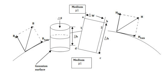
Figure: The boundary between conductor and free space.
Consider a boundary between conductor and free space. The conductor has infinite conductivity. For ideal conductor
The field intensity inside the conductor is zero and flux density inside a conductor is zero.
No charge can exist within a conductor. The charge appears on the surface in the form of surface charge density.
The charge density within the conductor is zero.
Thus  and
and  within the conductor is zero.
  is the surface charge density.
In order to determine the boundary conditions, use the closed path and Gaussian surface.
 at the boundary.
Let  be the electric field intensity in the direction making some angle with the boundary. This
  is resolved into two components
The component tangential to the surface
The component normal to the surface.

The integral of  carried over a closed contour is zero that is the work done in carrying unit positive charge along the closed path is zero.
Consider a rectangular closed path abcda as shown in figure. It is traced in clockwise direction hence

Is divided into four parts:

The closed contour is placed in such a way that its two sides a-b and c-d are parallel to tangential direction to the surface while the other two are normal to the surface at the boundary.
The rectangle with height  and width
  is placed in a manner that half of it is conductor and remaining half is free space. Thus
  is in the conductor and
  in free space.
The portion of c-d in conductor where  hence the corresponding integral is zero.

The width  therefore E is constant hence,

But  is tangential to the boundary hence
 where
where 
Ow b-c is parallel to the normal component therefore  along this direction. Let

For small height  EN is assumed constant and taken out of integration.

But out of b-c, b-2 is in free space and 2-c is in the conductor when 


For path d-a the condition is same as for b-c only direction is opposite.

Substituting eq 4 and 8 and 3 and 9 we get


Thus, the tangential component of the electric field intensity is zero at the boundary between conductor and free space.
DN at the boundary
To find the normal component of  select a closed Gaussian surface in the form of right circular cylinder as shown in figure.
  is placed in such a way that
  is in the conductor and
  is in free space. Its axis is normal direction to the surface.
According to Gauss’s law ,

The surface integral must be evaluated over three surfaces top , bottom and lateral.
Let the area of top and bottom be same S

The bottom surface is in conductor where  hence corresponding integral is zero.
The top surface is in free space hence top surface is shifted at the boundary with 

The lateral surface area is 2π r  where r is the radius of the cylinder. But as
  ->0 this area reduces to zero and the integral is zero.
While only component  is normal having magnitude DN the top surface is very small over which DN can be assumed constant and taken out of integration.


From Gauss’s Law

But at the boundary the charge exists in the form of surface charge density  s
s

Equating 16 and 17 we get


Thus the flux leaves the surface normally and the normal component of flux density is equal to surface charge density


Q15) Explain what is meant by relaxation time?
A16) When current flows, it is the time interval between two successive collisions of electrons in a conductor.
The following graph shows the link between relaxation time (T) and drift velocity (Vd).

Where
vd = drift velocity
e = charge of electron
E = field
m = mass of electron
T = Relaxation time
So, the expression for relaxation time (T) is

Let L = Length of the conductor
A = Area of the conductor
n = current density
Then current flowing through the conductor is

Field E can be expressed as
E = V/L
Then current flowing through the conductor becomes

From ohm’s law
V = IR
R = V/I

Q16) What is continuity equation derive expression?
A17) From the principle of charge conservation, the time rate of decrease of charge within a given volume must be equal to the net outward current flow through the surface of the volume. Thus current Iout coming out of the closed surface is
Iout = 

 …….(1)
Where Qin is the total charge enclosed by the closed surface. Applying divergence theorem:
 ……..(2)
But
 ………(3)
Substituting 2 and 3 in 1:

 ……..(4)
Which is called the continuity of current equation or just continuity equation. The continuity equation is derived from the principle of conservation of charge and essentially states that there can be no accumulation of charge at any point. For steady currents,  , and hence
  · J = 0, showing that the total charge leaving a volume is the same as the total charge entering it. Kirchhoff's current law follows from this.
Q17) What is meant by polarization. Explain its effect on dielectrics?
A18) To understand polarization, consider an atom of a dielectric. This consists of nucleus with positive and negative charge in the form of revolving electrons in the orbits. The negative charges are in the form of cloud of electrons.
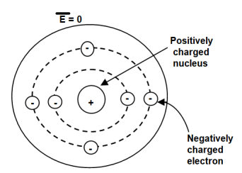
Figure. Unpolarized atom of a dielectric
The number of positive charges is same as negative charges and hence atom is electrically neutral. Due to symmetry both positive and negative charges are assumed to be point charges of equal amount coinciding at the centre. This is called unpolarized atom.
When electric field  is applied symmetrical distribution of charges gets disturbed. The positive charges experience a force
  while the negative charges experience a force -
  in opposite direction.
The separation between the nucleus and centre of atom is shown. Such an atom is polarized atom.
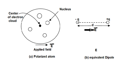
Figure. Polarized atom.
Expression:
When dipole is formed due to polarization there exists an electric dipole moment p.
 ----------------------(1)
Where
Q= magnitude of one of the two charges.
 = Distance vector from negative to positive charge.
Let
 Number of dipoles per unit volume
 Total volume of the dielectric
N= Total dipoles=n v
Then the total dipole moment is to be obtained using super position principle as,
 ----------------(2)
If dipoles are randomly oriented  is zero but if dipoles are aligned in the direction of applied E then has significant value.
The polarization  is defined as the total dipole moment per unit volume.

It is measured in coulombs per square meter (C/
------------------------(3)
It can be seen that the units of polarization are same as that of flux density  Thus polarization increases the electric flux density in a dielectric medium. Hence, we can write, flux density in dielectric is,

For isotropic and linear medium, the  and
and  are parallel to each other at every point and related to each other as,

Where  Dimensionless quantity called electric susceptibility of the material.
The susceptibility tells us how sensitive is a given dielectric to the applied electric field 
Substituting (5) in (4)


The quantity  is defined as relative permittivity or dielectric constant of the dielectric material

Q18) Compare conduction and convection current?
A19) When there is presence of some mechanical force which tends the charge particles to move but they are also opposed by the electric field results in some current flow called as convection current.
The movement of charged particle due to electric field and not due to any ither surrounding material is called as conduction current. In some materials, the electric field is also able to dislodge weakly-bound electrons from atoms, which then subsequently travel some distance before reassociating with other atoms. For this reason, the individual electrons in a conduction current do not necessarily travel the full distance over which the current is perceived to exist.
Conduction | Convection |
In conduction The heat transfer takes place between objects by direct contact. | In convection, The heat transfer takes within the fluid. |
The heat transfer takes place due to the difference in temperatures. | The heat transfer due to the difference in density. |
The heat transfer in conduction is slow | The heat transfer in convection is faster. |
The heat transfer occurs through a heated solid object. | The heat transfer occurs through intermediate objects. For example heat transfer between air and water. |
It does not follow the law of reflection and refraction | It does not follow the law of reflection and refraction |
Q19) Derive expression for energy density in electrostatic fields?
A20) Energy density is the amount of energy stored in each system or region of space per unit mass. Only the useful or extractable energy is quantified which is to say that chemically inaccessible energy such as rest mass energy is ignored. Consider a point charge Q1 transferred from infinity to position r1 in the system. It takes no work to bring the first charge from infinity since there is no electric field to fight against as the system is charge free.
W1=0 J
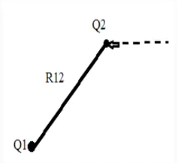
Now bring in another point charge Q1 from infinity to position r2 in the system. In this case we have do work against the electric field generated by the first charge Q1
W2 = Q1V21
V21= electrostatic potential at point r2 due to Q1
Work done now becomes
W2 = 
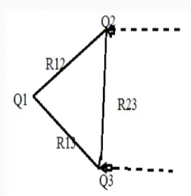
The work done required to bring Q3 to a distance R13 from Q1 and distance R23 from Q2 is
W3 = Q1 V31 +Q1 V32= Q1 (V31+V32)
V31 and V32 = electrostatic potential at point r3 due to Q1 and Q2 respectively.
The work done is simply the sum of the work done against the electric field generated by point charge Q1 and Q2 taken in isolation.
W3 = 
Thus, the total work done in assembling the three charges is given as
Wt=W1+W2+W3
Wt=0+Q2V21+Q3(V31+V32)
The total work done WE is given as
WE = 
If charges are positioned in reverse order, then the total work done is assembling them is given as
Wt=W3+W2+W1
Wt=0+Q2V23+Q3(V12+V13)
V31 and V32 = electrostatic potential at point r3 due to Q1 and Q2 respectively.
V23 = electrostatic potential due to r2 due to Q3
Adding above to equations
Wt= Q1(V12+V13) + Q2(V21+V23) +Q3(V31+V32) = Q1V1 + Q2V2 +Q3V3
Wt = 
V1, V2 and V3 = Potentials at position r1, r2 and r3
Energy for N point charges is
WE = 
The above equation means
a) This equation represents the potential energy of the system.
b) This is the work done in bringing the static charges from infinity and assembling them in the required system.
c) This is the kinetic energy which would be released if the system gets dissolved which means the charges returns to infinity.
For continuous charge density the line surface and volume charge will be given as
 (Line Charge)
 (Surface Charge)
 (Volume Charge)
Since  v=
v= 
And E= - 
Substituting in above equation the work done in assembling a volume charge distribution in terms of electric field and flux density will be
WE = 
This equation gives us the potential energy of a continuous charge distribution stored in an electric field.
The electrostatic energy density is given by
WE = 