Unit - 4
Magnetic Forces
Q1) A long, rigid wire lying along the y-axis carries a 5.0-A current flowing in the positive y-direction. (a) If a constant magnetic field of magnitude 0.30 T is directed along the positive x-axis, what is the magnetic force per unit length on the wire? (b) If a constant magnetic field of 0.30 T is directed 30 degrees from the +x-axis towards the +y-axis, what is the magnetic force per unit length on the wire?
A1) We start with the general formula for the magnetic force on a wire. We are looking for the force per unit length, so we divide by the length to bring it to the left-hand side. We also set sinθ=1.sinθ=1. The solution therefore is
F=IlBsinθ
F/l = (5.0A)(0.30 T)
F/l=1.5N/m.
F⃗/l = -1.5kN/m
The current times length and the magnetic field are written in unit vector notation. Then, we take the cross product to find the force:
F⃗ /l=Il⃗ ×B⃗ =(5.0A)ljˆ×(0.30Tcos(30°)iˆ+0.30Tsin(30°)jˆ)
F⃗ /l=−1.30kˆN/m.
Q2) A particle with charge of 2  is moving at 3x10⁶ metre per second perpendicularly through a magnetic field with a strength of 0.05 Tesla what is the magnitude of the force on the particle?
A2) The equation for finding the force on a moving charged particle in a magnetic field is as follows:
F=qv×B
Here, F is the force in Newtons, q is the charge in Coulombs, v is the velocity in m/s and B is the magnetic field strength in Teslas.
Another way to write the equation without the cross-product is as follows:
F=qvBsinθ
Here, θ is the angle between the particles velocity and the magnetic field.
For our problem, because theta is 90∘, sinθ evaluates to 1, so we just need to perform multiplication.

F=(2⋅10−6C)(3⋅106ms)(0.05T)
F=0.3N
Therefore, the force on the particle is 0.3N.
Q3) An 8cm wire with a current of 2A is oriented 36∘ from parallel to a magnetic field with a strength of 6T. What is the force on the wire?
A3) The equation for the force on a current carrying wire in a magnetic field is as follows:
F=IL⋅B=ILBsinθ
F is the force in Newtons, I is the current in amperes, B is the magnetic field strength in Teslas, and θ is the angle from parallel to the magnetic field.
Because our wire is not fully perpendicular to the magnetic field, it does not experience the full possible force. Instead, it experiences sin(36∘) times the maximum force value.
F=ILBsinθ
F=(2A)(0.08m)(6T)sin(36o)
F≈0.564N
Q4) A proton traveling at 1×10⁷ms in a horizontal plane passes through an opening into a mass spectrometer with a uniform 3T magnetic field directed upward. The particle then moves in a circular path through 180° and crashes into the wall of the spectrometer adjacent to the entrance opening. How far down from the entrance is the proton when it crashes into the wall?
The proton’s mass is 1.67∗10−27kg and its electric charge is 1.6∗10−19C.
A4) A charged particle moving through a perpendicular magnetic field feels a Lorentz force equal to the formula:
FB=qvB
q is the charge, v is the particle speed, and B is the magnetic field strength. This force is always directed perpendicular to the particle’s direction of travel at that moment, and thus acts as a centripetal force. This force is also given by the equation:
Fc=mv2/r
We can set these two equations equal, allowing us to solve for the radius of the arc.
QvB=mv2/r
r=mv/qB
Once the particle travels through a semicircle, it is laterally one diameter in distance from where is started (i.e. twice the radius of the circle).
r=mv/qB=(1.67×10−27kg)(1.0×107m/s)/(1.6×10−19C)(3T)=34.8mm
Twice this value is the lateral offset of its crash point from the entrance:
2(34.8mm) =69.6mm
Q5) What is the force experienced by a 15μC charge moving at 6.2⋅107m/s through a magnetic field with strength 7T at 48o from perpendicular to the field?
A5) To find the force experienced by the charge, we use this equation:
F=qv×B
Because the charge is moving at an angle from perpendicular, we need to take the cross product into account.
F=qvBsinθ
Theta is the angle from perpendicular, which is 48o. Plug in known values and solve.

F=4837.87N
Q6) An 8μC charge is moving through a 10T magnetic field at a speed of 2.5⋅107m/s perpendicular to the direction of the field. What is the force on the charge?
A6) The equation for force on a charge moving through a magnetic field is:
F=qv⋅B
Because the velocity is perpendicular to the field, the cross product doesn't matter, and we can do simple multiplication.
F=qvB
F=(8⋅10−6)(2.5⋅107)(10)
F=2000N
Therefore, the force on the charge is 2000N
Q7) A 5μC charge is moving through a 35T magnetic field at a speed of 3.1⋅107m/s 43o from parallel to the magnetic field. What is the force on the charge?
A7) The equation for force on a charge moving through a magnetic field is:
F=qv⋅B.
The cross product is:
F=qvBsinθ
Above, θ is the degree from parallel the charge is moving. The charge is moving at 43∘ from parallel, so the equation, once we plug in our numbers, is:
F=qvBsinθ
F=(5⋅10−6) (3.1⋅107)(35)(sin(43∘))
F=3699.84N
The force on the charge is about 3700N.
Q8) A current of 6A is flowing in a plane circular coil of radius 2 centimetre having 200 turns the coil is placed in a uniform magnetic field of 0.2 Weber per metre square if the coil is free to rotate what orientation would correspond to aide's stable equilibrium unstable equilibrium. Calculate the potential energy of the coil in these two cases?
A8) Area of coil A=  r2 = 3.14 x (0.02)2 = 1.256x10⁻³ m2
The magnetic moment of the coil M =N i A = 200 x 6 x 1.256 x 10-3 = 1.5072 A/m2
The potential energy of the coil when placed in a uniform magnetic field is given by
U0 = -M B cos
a) In case of stable equilibrium, the coil will Orient itself so as to have a minimum potential energy and this corresponds to  degree that is the axis of the coil will be parallel to the magnetic field
  parallel to
  .In this case the potential energy will be
U0 = -M B cos = -1.5072x 0.2=-0.30144 J
a) In case of unstable equilibrium, the coil will have maximum potential energy this will be so when  degree,
  anti-parallel to
  .In this case the potential energy will be
U0 = -M B cos 180 = 0.30144J
Q9) A shot bar magnet of magnetic momentum 0.05 joules per Tesla is held with its axis at 30 degree with a uniform external magnetic field of 0.15 Tesla find the magnitude of the torque exerted on the magnet by the magnetic field.
A9) The torque exerted on the bar magnet

= 0.50x 0.15xsin 300
= 0.050x 0.15x 0.50= 0.0375J
Q10) The component of the horizontal component of flux density of the earth's magnetic field is 1.7x10⁻⁵ Webber per metre square. What is the horizontal component of magnetic intensity?
A10) B= 
H= B/ = (1.7x10⁻⁵)/(1.26x10-6)
H= 13.5A/m
Q11) A bar magnet has a coercivity of 4x10³ A/m. It is desired to demagnetise it by inserting inside a solenoid of 12 centimetre long and having 60 turns. What current should be sent through the solenoid?
A11) The bar magnet requires a magnetic intensity H= 4x10³ A/m to demagnetised.
n=number of turns per unit length= 60/(12x10-2) = 500
Let I be the current carried by the solenoid to produce the magnetic intensity,
H=i n=(N/l)i
i=H/n= 4x10³/500 = 8A
Q12) A Material core has 1000 turns per metre of wire wound uniformly upon it which carries a current of 2 A the flux density in the material age 1 Webber per metre square calculate the magnetising force and magnetization of the material what would be the relative permeability of the core?
A12) n=100 turns/m
i=2A
 = 4
= 4 x10⁻⁷ Wb/A-m
Magnetizing force H = n i = 1000x2 = 2000A/m
But we already know that B=  (H+M)
(H+M)
Magnetization M= [B/ ]-H = 7.94x10⁵ A/m
Relative Permeability  = [B/H]/
  = 397
= 397
Q13) Find the H field within the slab when it is (a) permanently magnetized with magnetization Moi, (b) a linear permeable material with permeability A.
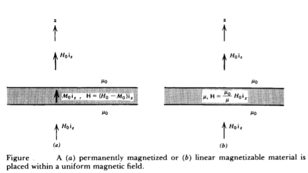
A13) For both cases, requires that the B field across the boundaries be continuous as it is normally incident. (a) For the permanently magnetized slab, this requires that
 oH0 =
oH0 =  o(H+M0)
H=H0-M0
Note that when there is no externally applied field (Ho = 0), the resulting field within the slab is oppositely directed to the magnetization so that B = 0.
(b) For a linear permeable medium requires
 oH0 =
oH0 =  o(H)
o(H)
H=  o/
o/ ) H0
) H0
For  >
>  o the internal magnetic field is reduced. If H0 is set to zero, the magnetic field within the slab is also zero
Q14) The amount of flux present in around magnetic bar was measured at 0.013 weber. If the material has a diameter of 14cm, calculate the flux density.
A14)
Area= r2
r2
Diameter=2r
r=14/2=7cm=0.07m
Area=3.14 x 0.072=0.0154m2
Flux Density B== A=0.013/0.0154=0.843 Tesla
Q15) Calculate the radius of the material having flux density of 0.5 T and flux present around the magnetic bar is 0.02T.
A15)
Flux Density B= A
A
A=  B=0.02/0.5=0.04 m2
Area= r2
r2
r=0.113m
Q16) A wire 2.5m long is bent into a square and into a circle. If the current flowing through the wire is 100 A, find the magnetising force at the centre of the square and the centre of the circle?
A16)
Value of h at centre of square will be H= =
=  =144 AT/m
Value of H at the centre of circle is H=I/2 r
r
=125.6AT/m
Q17) Calculate the magnetising force and flux density at a distance of 4cm from a long straight circular conductor carrying a current of 250A and placed in air?
A17)
H=I/2 r
r
=250/2 x 0.04=994.71 AT/m
B= μoH
=4 x10-7x994.71=1.25x10⁻³ Wb/m2
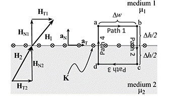
Q18) The magnetic field intensity is given as H1 = 6ax + 2ay + 3az (A/m) in a medium with mr1 = 6000 that exists for z < 0. We want to find H2 in a medium with mr2 = 3000 for z >0.
A18)
Step (a) and (b): The first step is to break H1 into its normal component (a) and its tangential component (b).
Step (c): With no current at the interface, the tangential component is the same on both sides of the boundary.
Step (d): Next, we find BN1 by multiplying HN1 by the permeability in medium 1.
Step (e): This normal component B is the same on both sides of the boundary.
Step (f): Then we can find HN2 by dividing BN2 by the permeability of medium 2.
Step (g): The last step is to sum the fields.
Q19) Explain the phenomenon of mutual inductance in the coil due to inductor?
A19)
Consider two stationary loops of wire, labeled 1 and 2—see Figure. Let us run a steady current I1 around the first loop to produce a magnetic field B1. Some of the field-lines of B1 will pass through the second loop. Let Φ2 be the flux of B1 through loop 2

Where dS2 is a surface element of loop 2. This flux is generally quite difficult to calculate exactly (unless the two loops have a particularly simple geometry). However, we can infer from the Biot-Savart law,

That the magnitude of B1 is proportional to the current I1. This is ultimately a consequence of the linearity of Maxwell’s equations. Here, dl1 is a line element of loop 1 located at position vector r1.
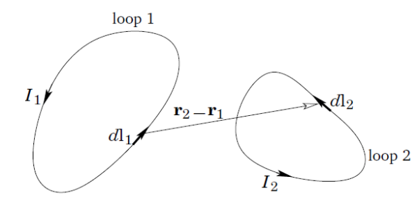
It follows that the flux Φ2 must also be proportional to I1. Thus, we can write
Φ2 = M21 I1,
Where M21 is a constant of proportionality. This constant is called the mutual inductance of the two loops.
Let us write the magnetic field B1 in terms of a vector potential A1, so that
B1 = ∇×A1.
It follows from Stokes’ theorem that

Where dl2 is a line element of loop 2. However, we know that

The above equation is just a special case of the more general law,

For j(r1) = dl1 I1/dl1 dA and d3r _ = dl1 dA, where dA is the cross sectional area of loop 1. Thus,

Where r2 is the position vector of the line element dl2 of loop 2, which implies that

In fact, mutual inductances are rarely worked out using the above formula, because it is usually much too difficult. However, this expression— which is known as the Neumann formula—tells us two important things. Firstly, the mutual inductance of two current loops is a purely geometric quantity, having to do with the sizes, shapes, and relative orientations of the loops. Secondly, the integral is unchanged if we switch the roles of loops 1 and 2. In other words,
M21 = M12.
Hence, we can drop the subscripts, and just call both these quantities M.
This is a rather surprising result. It implies that no matter what the shapes and relative positions of the two loops, the magnetic flux through loop 2 when we run a current I around loop 1 is exactly the same as the flux through loop 1 when we run the same current around loop 2.
We have seen that a current I flowing around some wire loop, 1, generates a magnetic flux linking some other loop, 2. However, flux is also generated through the first loop. As before, the magnetic field, and, therefore, the flux, Φ, is proportional to the current, so we can write
Φ = L I.
The constant of proportionality L is called the self-inductance. Like M it only depends on the geometry of the loop. Inductance is measured in SI units called henries (H): 1 henry is 1 volt-second per ampere. The henry, like the farad, is a rather unwieldy unit, since inductors in electrical circuits typically have inductances of order one micro-henry.
Q20) Derive the normal and tangential boundary conditions for magnetostatics?
A20) To derive normal and tangential boundary conditions for magnetostatics:
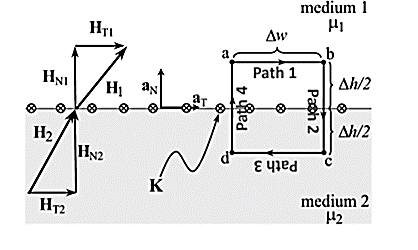
According to Ampere’s circuit law:
 dL = I enc
The current enclosed by the path is

Break H into four Integrals
 =Kw
=Kw
Path 1: =
=  T1 a T dL a T = H T1
Path 2:  N1 aN dL aN +
  N2 aN dL aN = -(HN1 + HN2)
Path 3:  dL =
dL =  T2aT dLaT= -HT2
Path 4:  dL =
dL =  N2dL aN+
  N1 a NdL aN = (H N1 + H N2)
Combing the results, we get
 dL = Ienc

Tangential BC = HT1 – HT2 = K
A more general expression for the first magnetostatic boundary condition can be written as

Where a21 is a unit vector normal going from media 2 to media 1.
Gauss’s Law for Magnetostatic fields:
 ds = 0
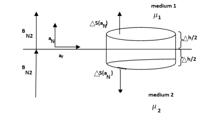
To find the second boundary condition, we center a Gaussian pillbox across the interface as shown in Figure.
We can shrink h such that the flux out of the side of the pillbox is negligible.
Then we have

For normal BC

Thus, we see that the normal component of the magnetic flux density must be continuous across the boundary.
B N1 = B N2

We can say that
H N1 ≠ H N2
Q21) What is magnetic torque? How is it produced explain in detail?
A21) Arrange a loop of wire so that the magnetic field pushes one way on one side and the other way the opposite side.
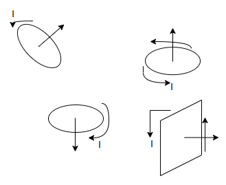
The current through a coil of wire immersed in a magnetic field causes magnetic force to spin the coil. Every loop of current and direction associated with it is perpendicular to the plane of the loop in the direction that right thumb would point if right fingers curled around the coil.
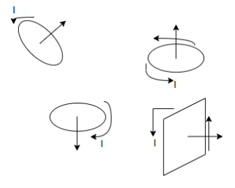
The magnetic force on a current carrying loop tries to align the loops normal vector with the magnetic field.
Suppose a magnetic field runs left to right then
The result of a push one way on one side of the coil and a push the other way on the other side is a torque an entity that causes the coil to spin.
The larger the torque the more resistance to spinning can be overcome. The torque on a coil of current carrying wire

Where
N= no of loops of wire in the coil.
I = current through coil
A = area of coil.
B = magnetic field strength (Tesla)
 angle between magnetic field and normal to coil.
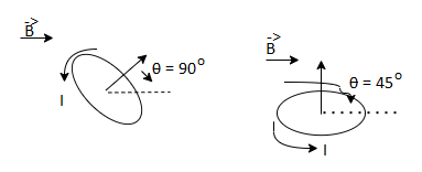
Magnetic moment
The magnetic moment is a vector relating torque of an object to the magnetic field. This is mathematically represented as:
τ = m × B
Where,
τ is the torque acting on the dipole
m is the magnetic moment
B is the external magnetic field
In the definition for the current loop, the Magnetic moment is the product of the current flowing and the area, M = I A
So, the unit conferring to this definition is articulated by Amp-m2.
It can also be suggested in terms of torque and moment. Conferring to that, the torque is measured in Joules (J) and the magnetic field is measured in tesla (T) and thus the unit is J T -1.
So, these two units are equivalent to each other and are provided by 1 Amp-m2 = 1 J T -1.
A Magnetic Dipole comprises two unlike poles of equivalent strength and parted by a small distance. For instance: The needle of a compass, a bar magnet, etc. are magnetic dipoles. We shall show that a current loop works as a magnetic dipole.
Magnetic Dipole Moment is described as the product of pole strength and the distance amidst the two poles. The distance between the two poles of a magnetic or a magnetic dipole is named as the magnet length and is given as the 2L.
Q22) What is Lorentz force? Derive the expression of the electromagnetic force exerted on the charge particle in magnetic field?
A22) It is the force exerted on the charged particle q moving with velocity v through an electric field E and magnetic field B. The entire electromagnetic force F on the charged particle is called Lorentz force which is given by
F = qE + qv x B ---------------------(1)
The first term indicates electric field. The second term indicates magnetic force which has direction perpendicular to both velocity and magnetic field.
The magnetic force is proportional to q and to the magnitude of the vector cross product v × B. In terms of the angle ϕ between v and B, the magnitude of the force equals qvB sin ϕ.
If v is perpendicular to B the particle will follow circular trajectory with radius of r = mv/qB. If the angle ϕ is less than 90°, the particle orbit will be a helix with an axis parallel to the field lines.
If ϕ is zero, there will be no magnetic force on the particle, which will continue to move undeflected along the field lines.
When a conductor is placed with B field perpendicular to current, the magnetic force on both types of charge carriers is in the same direction. This force gives rise to small potential difference between the sides of the conductor.
If a wire with a current i is placed in an external magnetic field B, Since, current represents movement of charges in the wire, the Lorentz force acts on the moving charges. Because these charges are bound to the conductor, the magnetic forces on the moving charges are transferred to the wire.
The force on a small length dl of the wire depends on the orientation of the wire with respect to the field. The magnitude of the force is given by I dlB sin ϕ, where ϕ is the angle between B and dl. There is no force when ϕ = 0 or 180°, both of which correspond to a current along a direction parallel to the field. The force is at a maximum when the current and field are perpendicular to each other. The force is given bydF= idl × B.
Q23) Define magnetic field strength of magnetic materials?
A23) The Magnetic Field Intensity or Magnetic Field Strength is a ratio of the MMF needed to create a certain Flux Density (B) within a material per unit length of that material.
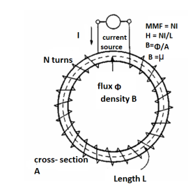
H = At/m, ampere-turns per meter. N is used as the number of turns of wire around a core or magnetic material. So, H = N*I/m.
This is the horizontal axis of the B-H curve for magnetic materials, and is used to vary the magnetic flux within the material by varying the current in the solenoid, thus varying the At (varying the amperes of the ampere-turns).
To determine the B-H curve of a material, the H is varied by controlling the magnitude and polarity of the current flowing in the coil around the sample material, and B is measured
Q24) Explain the phenomenon of magnetic hysteresis with the help of BH curve?
A24) In a magnetic circuit, this field is represented by magnetomotive force. It is analogous to the electromotive force in electrical circuit. This field is responsible to “set up” certain flux, which in turn gives rise to certain flux density B. Note that, here H is cause and B is its effect. The amount of flux which can be setup in a material is determined by an inherent property of the material, called as permeability, denoted by µ.
B = µH
When external magnetic field H is applied to a material, all the domains align in a particular direction, setting up net flux in the material. Due to domain alignment B (i.e. the magnitude of B) increases. However, after a certain value of B, the slope of B − H curve starts reducing as shown in Figure below
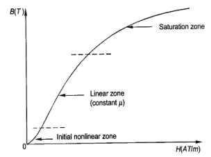
Fig: Magnetization curve
B-H Curve:
We cannot measure B and H directly. Further if we have transformer, we only have terminal measurements are with us. Hence, it is required to process the signals to get values of B and H. From Faraday’s law, V = N dφ/dt . Also, B is directly proportional to flux φ.
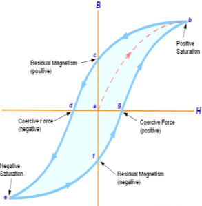
Fig: B-H curve
The lag or delay of a magnetic material known commonly as Magnetic Hysteresis. The Magnetic Hysteresis loop above, shows the behaviour of a ferromagnetic core graphically as the relationship between B and H is non-linear. Initially both B and H will be at zero, point 0 on the magnetisation curve.
If the magnetisation current, i is increased in a positive direction to some value than the magnetic field strength H increases linearly with i and the flux density B also increases (curve from point 0 to point a) as it heads towards saturation.
Now if the magnetising current in the coil is reduced to zero, the magnetic field circulating around the core also reduces to zero. However, the coils magnetic flux will not reach zero due to the residual magnetism present within the core and this is shown on the curve from point a to point b.
To reduce the flux density at point b to zero we need to reverse the current flowing through the coil. The magnetising force which must be applied to null the residual flux density is called a “Coercive Force”. This coercive force reverses the magnetic field re-arranging the molecular magnets until the core becomes unmagnetized at point c.
An increase in this reverse current causes the core to be magnetised in the opposite direction and increasing this magnetisation current further will cause the core to reach its saturation point but in the opposite direction, point d on the curve.
This point is symmetrical to point b. If the magnetising current is reduced again to zero the residual magnetism present in the core will be equal to the previous value but in reverse at point e.
Again, reversing the magnetising current flowing through the coil this time into a positive direction will cause the magnetic flux to reach zero, point f on the curve and as before increasing the magnetisation current further in a positive direction will cause the core to reach saturation at point a.
Then the B-H curve follows the path of a-b-c-d-e-f-a as the magnetising current flowing through the coil alternates between a positive and negative value such as the cycle of an AC voltage. This path is called a Magnetic Hysteresis Loop.