Unit - 5
Waves and Applications
Q1) Derive expression for general solution of E and I?
A1) The general solution of a transmission line includes the expressions for current and voltage at any point along the line of any length having uniformly distributed constants.
The various notations used in this derivation are,
R=Series resistance, ohms per unit length, including both the wires
L=Series inductance, henry per unit length
C=Capacitance between the conductors, farads per unit length
G=Shunt leakage conductance between the conductors, mhos per unit length
L= Series reactance per unit length
C=Shunt susceptance in mhos per unit length
Z=R+jL=Series impedance in ohms per unit length
Y=G+jC=Shunt admittance in mhos per unit length
S=Distance upto point of consideration, measured from receiving end
J=Current in the line at any point
E=Voltage between the conduction at any point
l=Length of the line
The transmission line of length l can be considered to be made up of infinitesimal T sections . One such section of length ds is shown in figure. It carries current I.

Fig: Circuit Diagram of Transmission Line
The point under consideration is at a distance s from the receiving end. The length of section is ds hence its series impedance is Zds and shunt admittance is Yds. The current is I and voltage E.
The elemental voltage drop in the length ds is
DE=IZ ds
DE/ds=I Z
The leakage current flowing through shunt admittance from one conductor to other is given by, dI=EY ds
 (1)
(1)
Differentiating equations (1) and (2) with respect to s we get

 (2)
(2)
This is because both E and I are functions of s.
 (3)
(3)
 (4)
(4)
The equations (3) and (4) are the second order differential equations describing the transmission line having distributed constants all along its length. It is necessary to solve these equations to obtain expressions of E and I.
Replace the operator d/ds by m we get
 but
but 
 (5)
(5)
So there exists two solutions for positive sign of m and negative side of m. The general solution for E and I are
 (6)
(6)
 (7)
(7)
Where A,B,C, and D are arbitrary constants of integration.
Q2) What is uniform ideal transmission line?
A2) An ideal transmission line has these properties:
- No distortion
- No attenuation
Sufficient conditions for building an ideal transmission line are that you have two perfect conductors with zero resistance, uniform cross section, separation much smaller than the wavelength of the signals conveyed, and a perfect (lossless) dielectric. Voltages impressed upon one end of such an ideal transmission line will propagate forever, at constant velocity, without distortion or attenuation.
The propagation velocity, or transmission velocity, of a line is rated in units of m/s. The symbol for propagation velocity is v. This quantity indicates how far your signals will travel in every unit of time. For the case of perfect, zero-resistance conductors surrounded by a perfect vacuum, the propagation velocity equals c, the velocity of light in a vacuum, approximately 2.998 ·10 8 m/s.
The characteristic impedance of an ideal transmission line remains constant at all frequencies. It has no imaginary part and is not a function of frequency. It is a function only of the physical geometry of the transmission line and the dielectric constant of the insulation.
Q3) Wave Reflection at a Discontinuity in an Ideal Transmission Line
A3) We now consider the case of a junction between two lines having different values for the parameters and as shown in Figure. Assuming that a wave of voltage and current is incident on the junction from line 1, we
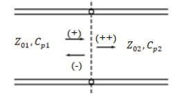
Fig: Transmission-line junction for illustrating reflection and transmission resulting from an incident wave
Find that the wave alone cannot satisfy the boundary condition at the junction, since the voltage-to-current ratio for that wave is whereas the characteristic impedance of line 2 is Hence, a reflected wave and a transmitted wave are set up such that the boundary conditions are satisfied. Let the voltages and currents in these waves be and respectively, where the superscript denotes that the transmitted wave is a wave resulting from the incident wave. We then have the situation shown in Figure below.
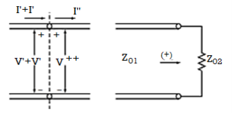
Fig (a) For obtaining the reflected wave and transmitted wave voltages and currents for the system of Fig (b) Equivalent to (a) for using the reflection coefficient concept.
Using the boundary conditions at the junction, we then write


But we know that and H


Thus, to the incident wave, the transmission line to the right looks like its characteristic impedance as shown in Figure (b). The difference between a resistive load of and a line of characteristic impedance is that, in the first case, power is dissipated in the load, whereas in the second ease, the power is transmitted into the line
We now define the voltage transmission coefficient, denoted by the symbol as the ratio of the transmitted wave voltage to the incident wave voltage. Thus,

The current transmission coefficient, which is the ratio of the transmitted wave current to the incident wave current, is given by

At this point, one may be puzzled to note that the transmitted voltage can be greater than the incident voltage if is positive. However, this is not of concern, since then the transmitted current will be less than the incident current. Similarly, the transmitted current is greater than the incident current when is negative, but then the transmitted voltage is less than the incident voltage. In fact, what is important is that the transmitted power is always less than (or equal to) the incident power since

Q4) Explain matching of load by λ/4 matching network?
A4) Let us consider TL (with characteristic impedance Zo) where the end is terminated with a resistive that is real load.

Figure. Mismatch
The solution for this is to place a matching network between the line and the load.
 Figure. Matching network
The quarter-wave transformer is simply a transmission line with characteristic impedance Z1 and length l = λ/4 (i.e., a quarter-wave line).

Figure. λ/4 matching network
We know that the input impedance of the quarter wavelength line is:
Zin = (Z1) 2/ ZL = (Z1) 2/ RL
Thus, if we wish for Zin to be numerically equal to Z0 , we find:
Zin = (Z1) 2/ RL = Zo
Solving for Z1 , we find its required value to be:
Z1 = √Zo RL
Therefore, a λ/4 line with characteristic impedance 𝑍1 =  𝑍0𝑅𝐿 will match a transmission line with characteristic impedance Z0 to a resistive load RL
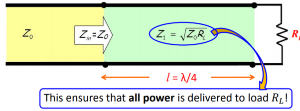
Figure. Power delivered to load.
Q5) Explain single stub matching technique?
A5) A stub is a short-circuited section of a transmission line connected in parallel to the main transmission line. A stub of appropriate length is placed at some distance from the load such that the impedance seen beyond the stub is equal to the characteristic impedance. Suppose we have a load impedance connected to a transmission line with characteristic impedance. The objective here is that no reflection should be seen by the generator. In other words, even if there are standing waves in the vicinity of the load, the standing waves must vanish beyond certain distance from the load. Conceptually this can be achieved by adding a stub to the main line such that the reflected wave from the short-circuit end of the stub and the reflected wave from the load on the main line completely cancel each other at point B to give no net reflected wave beyond point B towards the generator. We make use of Smith chart for this purpose

Fig. Single Stub Matching Technique
Since we have a parallel connection of transmission lines, it is more convenient to solve the problem using admittances rather than impedances. To convert the impedance into admittance also we make use of the Smith chart and avoid any analytical calculation. Now onwards treat the Smith chart as the admittance chart
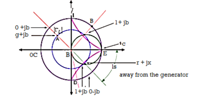
Matching Procedure
First mark the load admittance on the admittance smith chart (A). Plot the constant  circle on the smith chart. Move on the constant
  circle till you intersect the constant g=1 circle this point of intersection corresponds to point 1+jb’ (B). The distance traversed on the constant circle is l1. This is the location of placing the stub on the transmission line from the load end. Find constant suseptance jb’ circle. Find mirror image of the circle to get -jb’ circle. Mark 0-jb’ on the outer most circle (D). From (D) move circular clockwise upto s.c point (E) to get the stub length ls.
Q6) Derive electric field and magnetic field wave equation?
A6) Maxwell’s equation can be combined into a wave equation by making use of the vector identity
 (1)
(1)
Let us apply the identity above to the Maxwell’s electric field curl equation
 (2)
(2)
In a region of space free of charges, ∇~ ·E~ = 0. Assuming that we are only interested in well-behaved analytic functions (ie, those for which we can reverse the order of differentiations with impunity), we can transform the magnetic field term in Equation 2 from the curl of a time derivative to the time derivative of a curl.


If we assume that the region of interest is also current-free, we can replace D~ with  E~ to obtain

Above equation is the wave equation for electric field. Similarly, the wave equation for magnetic field is given below

Q7) What is displacement current explain in detail?
A7) The sort of current created as a result of the rate of electric displacement field D is known as displacement current. It's a time-varying quantity that Maxwell's equations introduce. It's explained in terms of electric current density units. The law of Ampere circuits introduces it.
Ampere is the SI unit for displacement current (Amp). This dimension can be measured in length units, which can be maximum, minimum, or equivalent to the actual distance travelled from start to finish.
Derivation
Consider the fundamental circuit that gives the displacement current in a capacitor to understand the displacement current formula, dimensions, and derivation of displacement current.
Consider a parallel plate capacitor with a power supply requirement. When power is applied to the capacitor, it begins to charge and there is no current flow at first. The capacitor charges continually and builds above the plates as time passes. A change in the electric field between the plates during the charging of a capacitor over time causes the displacement current.
From the given circuit, consider the area of the parallel plate capacitor = S
Displacement current = Id
Jd = displacement current density
d= €E ie., related to electric field E
€ = permittivity of the medium between the plates of a capacitor
The displacement current formula of a capacitor is given as,
Id= Jd × S = S [dD / dt]
Since Jd = dD/dt
The displacement current will have the same unit and effect on the magnetic field as the conduction current, according to Maxwell's equation.
▽×H=J+Jd
Where,
H = magnetic field B as B=μH
μ = permeability of the medium in between the plates of a capacitor
J = conducting current density.
Jd =displacement current density.
As we know that ▽(▽×H) =0 and ▽. J=−∂ρ/∂t=−▽(∂D/∂t)
By using Gauss’s law that is ▽. D=ρ
Here, ρ = electric charge density.
Hence, we can conclude that, Jd=∂D/∂t displacement current density and it is necessary to balance RHS with LHS of the equation.
Q8) List all the properties of displacement current?
A8) Properties
The following are the properties of displacement current: • It is a vector quantity that obeys the continuity property in a closed path. • It varies with the rate of change of current in an electric density field.
• When the current in a wire's electric field is constant, it gives zero magnitudes.
• An electric field's fluctuating time is a factor.
• It had a positive, negative, or zero magnitude with both direction and magnitude.
• Regardless of the path, the length of this can be taken as the shortest distance between the starting and ending points.
• It can be measured in length units.
• It has a minimum, maximum, or equivalent magnitude of displacement to the actual distance from the spot for a certain period.
• It is dependent on the presence of an electromagnetic field.
• When the starting and finishing points are the same, it returns zero.
Q9) Derive Maxwells equation in final form?
A9) The static electric field  exist without a magnetic field
  demonstrated by a capacitor with static charge Q.
Similarly, a conductor with constant current I has magnetic field  in absence of an electric field
  .
.
But in time varying fields  cannot exist without each other.
Maxwell’s equations are nothing but set of four expressions derived from Ampere’s circuit law, Farady’s law, Gauss’s law for electric field and Gauss’s law for magnetic field.
- Maxwell’s equation derived from Faradays law:
According to the concept from electrostatic field the work done over a closed path or closed contour that is starting point same as terminating point is always zero.
Mathematically it can be represented as
 -----------------------(1)
The above equation is called integral form of Maxwell’s equation derived from Faradays law of static field.
Using Stroke’s theorem converting close line integral into surface integral we get


But  cannot be zero which means
  = 0.
= 0.
Point form of Maxwell’s equation derived from differential form.
- Maxwell’s equation derived from Ampere’s Circuital Law:
According to the basic concept of magnetostatics an Amper’s circuital law states that the line integral of magnetic field intensity  around closed path is exactly equal to direct current enclosed by that path.
Mathematically 
Now the current enclosed is equal to the product of current density normal to the closed path and area of closed path. Hence, we get
 where
where
Hence evaluating the above equations, we get

The above expression is integral form of Maxwell’s equation from Ampere circuital law for static field.
Now by applying Stoke’s theorem LHS of the equation can be converted into surface integral

Hence, we get

- Maxwell’s equation derived from Gauss Law:
According to Gauss law of electrostatic fields the electric flux through any closed surface is equal to the total charge enclosed by that surface. Mathematically we can write
 1
1
The most common form to represent Gauss law mathematically is volume charge density Pv hence, we can write
 ----2
----2
The above equation is called integral form of Maxwell’s equation derived from Gauss Law.
To establish the relationship between  and Pv converting closed surface integral into volume integral using divergence theorem as
 ----3
----3
Comparing 2 and 3 we get

- Maxwell’s equation derived from Gauss Law for Magnetostatic field.
According to Gauss law for magneto static field the magnetic flux cannot reside in closed surface due to non-existence of single magnetic pole.
Mathematically we can write

The above equation is called Integral form of Maxwell’s equation derived from Gauss law for static magnetic field.
Now using divergence theorem we can write


Now dV cannot be zero that means  .
.
Q10) Derive expression for plane wave in good conductor?
A10) A uniform plane wave with x-directed electric field is normally incident upon a perfectly conducting plane at z =0, as shown in Figure. The presence of the boundary gives rise to a reflected wave that propagates in the -z direction. There are no fields within the perfect conductor. The known incident fields traveling in the +z direction can be written as


While the reflected fields propagating in the -z direction are similarly


Where in the lossless free space

The minus sign difference in the spatial exponential phase factors of (1) and (2) as the waves are traveling in opposite directions. The amplitude of incident and reflected magnetic fields are given by the ratio of electric field amplitude to the wave impedance.
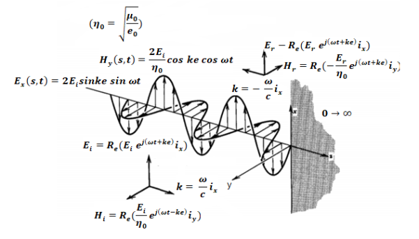
The negative sign in front of the reflected magnetic field for the wave in the -z direction arises because the power flow S, = E, x H, in the reflected wave must also be in the -z direction. The total electric and magnetic fields are just the sum of the incident and reflected fields. The only unknown parameter E, can be evaluated from the boundary condition at z =0 where the tangential component of E must be continuous and thus zero along the perfect conductor:
The total fields are the sum of incident and reflected fields

=
=

=
=
The electric and magnetic fields are 90* out of phase with each other both in time and space.
Q11) Define Poynting theorem and also prove it?
A11) Poynting theorem states that the net power flowing out of a given volume V is equal to the time rate of decrease of stored electromagnetic energy in that volume decreased by the conduction losses is the total power leaving the volume = rate of decrease of stored electromagnetic energy ohmic power dissipated due to motion of charge.
Proof:
The energy density carried by the electromagnetic wave can be calculated using Maxwell's equations


 (5)
(5)
 (6)
(6)
 (7)
(7)


=

So from equation (vii) 
 (viii)
Integrating equation (viii) over a volume V enclosed by a surface S

Or 
As 
Or 
Or 
Or 
That is the Total power leaving the volume = rate of decrease of stored e.m.f energy - ohmic power dissipated due to charge motion
This equation (ix) represents the poynting theorem according to which the net power flowing out of a given volume is equal to the rate of decrease of stored electromagnetic energy in that volume minus the conduction losses.
Q12) When incident wave is normal derive the expression for its reflection?
A12) Consider the case of a plane wave travelling in the x direction incident on a boundary parallel to the plane x=0 as shown in figure 6.7. Let  be the dielectric field strength of the incident wave striking the boundary,
  be the electric field strength of the transmitted wave propagated in the second medium.
Similarly let 
 represents magnetic field.
Again let  be the constants of the first medium and
  those of the second then the following relation will hold


The continuity of tangential component of  required that

And, 


Therefore for electric field reflection coefficient

And transmission coefficient


Similarly for magnetic field
 (6.14)
 (6.15)
The permeability of all known perfect dielectrics that is insulators do not differ appreciable from that of free space so that  Inserting this relation in the above equation we have for electric field


Similarly for magnetic field


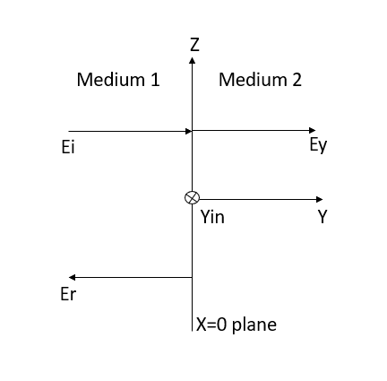
Figure: Reflection by a perfect dielectric, normal incidence.
Q13) Explain distributed parameters of the transmission line?
A13) A transmission line is a means of transfer of information from one point to another. Usually, it consists of two conductors. It is used to connect a source to a load. The source may be a transmitter and the load may be a receiver.
The performance of transmission line depends on the parameters of the line. The transmission line has mainly four parameters, resistance, inductance, capacitance and shunt conductance. These parameters are uniformly distributed along the line. Hence, it is also called the distributed parameter of the transmission line.
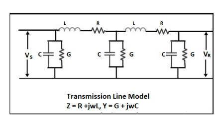
Figure. Transmission Line
The inductance and resistance form series impedance whereas the capacitance and conductance form the shunt admittance.
Line inductance – The current flow in the transmission line induces the magnetic flux. When the current in the transmission line changes, the magnetic flux also varies due to which emf induces in the circuit. The magnitude of inducing emf depends on the rate of change of flux. Emf produces in the transmission line resist the flow of current in the conductor, and this parameter is known as the inductance of the line.
Line capacitance – In the transmission lines, air acts as a dielectric medium. This dielectric medium constitutes the capacitor between the conductors, which store the electrical energy, or increase the capacitance of the line. The capacitance of the conductor is defined as the present of charge per unit of potential difference.
Capacitance is negligible in short transmission lines whereas in long transmission; it is the most important parameter. It affects the efficiency, voltage regulation, power factor and stability of the system.
Shunt conductance – Air act as a dielectric medium between the conductors. When the alternating voltage applies in a conductor, some current flow in the dielectric medium because of dielectric imperfections. Such current is called leakage current. Leakage current depends on the atmospheric condition and pollution like moisture and surface deposits.
Shunt conductance is defined as the flow of leakage current between the conductors. It is distributed uniformly along the whole length of the line. The symbol Y represented it, and it is measured in Siemens.
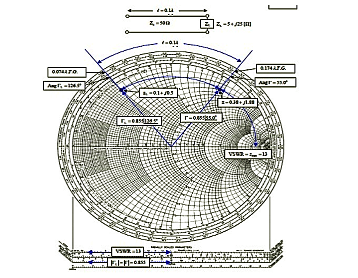
Q14) The 0.1λ length line shown has a characteristic impedance of 50 and is terminated with a load impedance of ZL = 5+j25.
(a) Locate zL = ZL/Z0 = 0.1 + j0.5 on the Smith chart.
(b)What is the impedance at l = 0:1λ?
Since we want to move away from the load (i.e., toward the generator), read 0.074 λ on the wavelengths toward generator scale and add l = 0.1 λ to obtain 0.174 λ on the wavelengths toward generator scale.
A radial line from the center of the chart intersects the constant reflection Co-efficient magnitude circle at z = 0.38 + j1.88. Hence Z = zZ0 = 50(0.38 + j1.88) = 19 + 94Ω.
(c) What is the VSWR on the line?
Find VSWR = Zmax = 13 on the horizontal line to the right of the chart's center. Or use the SWR scale on the chart.
(d) What is ΓL?
From the reflection coefficient scale below the chart,
Find |ΓL| = 0.855. From the angle of reflection coefficient scale on the perimeter of the chart, Find the angle of ΓL=126.5₀. HenceΓL=0.855e j126.5₀.
(e) What is Γ at l = 0.1λ from the load?
A14)
Note that |Γ| =|ΓL|=0.855. Read the angle of the reflection coefficient from the angle of reflection coefficient scale as 55.0₀. Hence ΓL=0.855e j126.5₀.
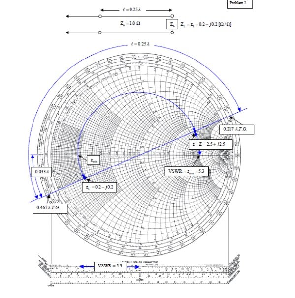
Q15) A transmission line has Z0 = 1.0, ZL = zL = 0.2- j0.2Ω.
(a) What is z at l =λ/4=0.25 λ?
(b) What is the VSWR on the line?
(c) How far from the load is the first voltage minimum?
A15)
(a) What is z at l =λ/4=0.25 λ?
From the chart, read 0:467λfrom the wavelengths to-ward generator scale. Add 0.25λ to obtain 0.717 λ on the wavelengths toward generator scale. This is not on the chart, but since it repeats every half wavelength, it is the same as 0.717 λ– 0.500 λ = 0.217 λ. Drawing a radial line from the center of the chart, we find an intersection with the constant reflection coefficient magnitude circle at z = Z = 2.5 + j2.5.
(b) What is the VSWR on the line?
From the intersection of the constant reflection coefficient circle with the right hand side of the horizontal axis, read VSWR= zmax = 5.3.
(c) How far from the load is the first voltage minimum?
The voltage minimum occurs at zmin which is at a distance of 0.500λ-0.467λ = 0:033λ from the load. Or read this distance directly on the wavelengths toward load scale. The current minimum occurs at zmax which is a quarter of a wavelength farther down the line or at 0.033λ+0.25λ = 0.283λ from the load.
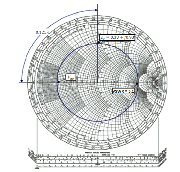
Q16) A slotted line measurement yields the following parameter values:
(a) Voltage minima at 9.2 cm and 12.4 cm measured away from the load with the line terminated in a short.
(b) VSWR = 5.1 with the line terminated in the unknown load; a voltage minimum is located 11.6 cm measured away from the load.
What is the normalized line impedance?
A16)
Note that this data could have come from either a waveguide or a TEM line measurement. If the transmission system is a waveguide, then the wavelength used is actually the guide wavelength. From the voltage minima on the shorted line, the (guide) wavelength may be determined:
λg/2=12.4cm-9.2 cm=3.2 cm or λg=6.4 λg
Hence the shift in the voltage minimum when the load is replaced by a short is
12.4cm-11.6cm/6.4cm/ λg=0.125 λg
Toward the generator. Locate the reflection coefficient magnitude circle by its intersection with zmax = VSWR = 5:1 on the horizontal axis. Then from the voltage minimum opposite zmax, move 0.125 λg toward the generator to find a position an integral number of half-wavelengths from the load. The impedance there is the same as that of the load, zL = 0.38 +j0.93. Alternatively, move 0.5 λg– 0.125 λg = 0.375 λg toward the load to locate the same value.
General solution, physical significance of the equations, wavelength, velocity of propagation, the distortion less line, Reflection on a line not terminated in Z0, reflection coefficient, open and short circuited lines, reflection factor and reflection loss, standing waves; nodes; standing wave ratio, Input impedance of dissipation less line, Input impedance of open- and short-circuited lines, Power and impedance measurement on lines, Reflection losses on the unmatched Load, Problems solving using Smith chart.
- Short-Circuit Lines:
Consider a transmission line of length L, but suppose the end of line is short-circuited together so that ZA =0. Then the impedance equation is:

We can determine input impedance for short circuit line:(input admittance 1/Z)
 (short-circuited Line)
 (short-circuited admittance)
Q17) Suppose an antenna has an impedance ZA = 50 – j * 10. Using short-circuit transmission line with Z0 = 50 and u=c in parallel with antenna. Transform the input impedance to be entire real.
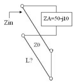
A17) The admittance of the load is:
YA = 1/ZA = 1/ (50 – j * 10) = YA = 0.0192 + j * 0.0038
If reactance is added in parallel with a value of YA = - j * 0.0038 the admittance will be entirely real so the impedance will real.
Q18) Derive the solution for Maxwells equation for uniform plane wave?
A18) The sources of time varying electromagnetic fields are time varying charges and currents, whether man-made or naturally occurring. However, examination of Maxwell’s equations shows that, even in empty space (with no sources), and fields cause each other. This means that, although these fields must originate in source regions, they can propagate through source-free regions. Because solutions in source regions are very hard to obtain, let us consider what kind of fields can exist in source-free regions.


These equations are still very complicated (4 different partial derivatives). Let’s try to find simple solutions. We do this by making assumptions. After finding simplest solutions, we:
(i) Find what kind of source would generate this type of field (waves).
(ii) Show that these simple solutions are useful approximations to real electromagnetic waves.
Assumption for Solution:
Can we find a solution such that:
1.) No variation exists in x and y directions.
2.)  or
or  also is oriented along one of the axes.
Ampere’s Law becomes:

Or, with our assumptions:

Compare for transmission line:

In a similar manner,
 ………….(1)
Faraday’s Law becomes:
 ………….(2)
Thus, if  is only in the
  direction, then is only in the .If we differentiate (2) with respect to z, we get:
Substitute from (2), 
We get 
This is called the wave equation.
Compare for transmission line: (same).

We will assume dielectric media; lossless:

Dimensional analysis:


In the units we are using:


By exactly the same method, we also get:


For example, the same equation is true for  and
and  . Thus,
 and
and  must have the same type of functional dependence. This wave equation still has many possible solutions. In fact, it can be shown by direct substitution that

Are the solutions

t is important to note that f1 and f2 can be any function.
The field we find directly from the equation:

Suppose
 …………(3)
Differentiate (3) with respect to z
 …………(4)
Integrate with respect to time
 …………(5)

This leads to a new quantity that relates the electric and magnetic fields:


Rewriting:
Units of  =
=  =
= = Ω
= Ω
 = Impedance of free space =
  =377 Ω
 = impedance of a lossless dielectric =
  =
= =
=
Note that  and
and  are in time phase and space quadrature
The directions of the vectors are such that:


This vector  , always points in the direction of propagation. These types of waves are called Uniform Plane Electromagnetic Waves.
“Plane” refers to the fact that, at any instant in time, the surfaces of constant phase are planes (here, constant).
“Uniform” means no variation in transverse direction. The wave derived here is one oscillating at a single frequency. The frequency is determined by the source. If the source has multiple frequencies, so will the wave. In communications, modulating a carrier wave results in multiple frequencies. But before we can study such fields, we must thoroughly understand single frequency sinusoidal waves.
Q19) Define faradays law of EMI?
A19)
- First law: whenever flux linkage with the coil changes an emf is induced in that conductor
- Second law: the magnitude of induced emf is equal to the rate of change of flux linkage
Explanation: suppose a coil has n turns and flux through it change from initial value of Ø1 to Ø2 in line t sec
Initial flux linkage = N Ø
Final flux linkage = NØ2
 Induced emf e =
Putting the above equation in differential form
e = rate of change of flux linkage

The direction of this induced emf is given by lenis law which states the polarity of induced emf is always such that it tends to set up a current which flow in such a direction so as to oppose the cause that produces it.

Q20) What does motional electromotive force means explain?
A20) We all know that when an electrical conductor is introduced into a magnetic field, due to its dynamic interaction with the magnetic field, emf is induced in it. This emf is known as induced emf. In this article, we will learn about motional emf where emf is induced in a moving electric conductor in the presence of a magnetic field.
Consider a straight conductor PQ as shown in the figure, moving in the rectangular loop PQRS in a uniform and time-independent magnetic field B, perpendicular to the plane of the system.
Let us suppose the motion of rod to be uniform at a constant velocity of v m/sec and the surface to be frictionless.
Thus, the rectangle PQRS forms a closed circuit enclosing a varying area due to the motion of the rod PQ.
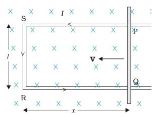
The magnetic flux ΦB enclosed by the loop PQRS can be given as
ΦB = Blx
Where, RQ = x and RS = l, Since the conductor is moving, x is changing with time. Thus, the rate of change of flux ΦB will induce an emf, which is given by:
ϵ =−dϕB/dt=−d(Blx)/dt=−Bldx/dt=Blv
Where, the speed of conductor (PQ), v = -dx/dt and is the formula of induced emf. This induced emf due to the motion of an electric conductor in the presence of the magnetic field is called motional emf. Thus, emf can be induced in two major ways:
Due to the motion of a conductor in the presence of a magnetic field.
Due to the change in the magnetic flux enclosed by the circuit.
This concept of motional emf can be explained with the help of the concept of Lorentz force acting on free charge carriers of the conductor. Let us consider any arbitrary charge q in the conductor PQ. As the rod moves with a constant speed v, the charge is also moving with a speed v in the presence of magnetic field B. The Lorentz force on this charge is given by:
F = qvB
The work done in moving the charge from P to Q can be given by,
W = QBvl
Since, emf is defined as the work done per unit charge,
∈ = wq=Bvl